IPhone SoundFrame
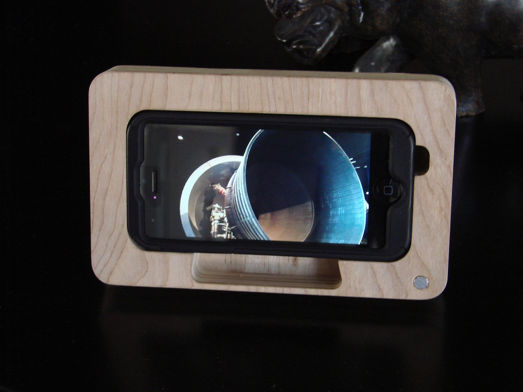
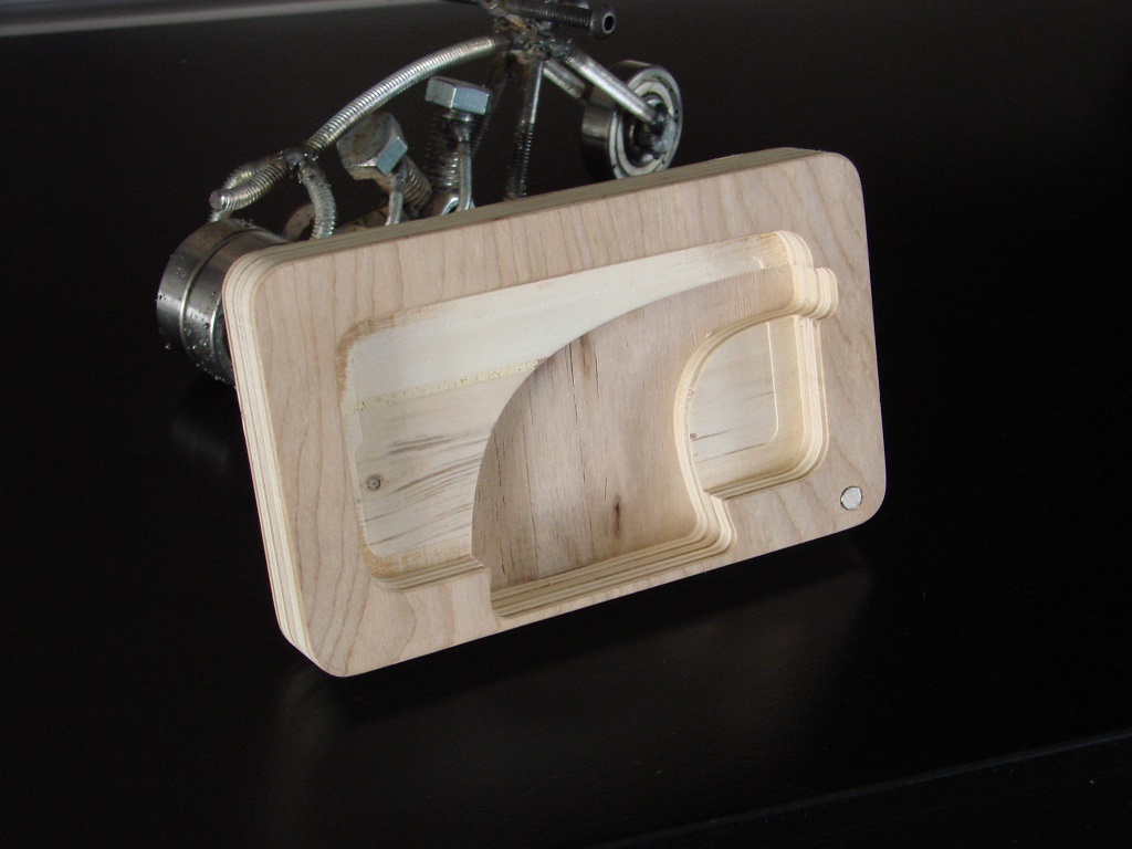
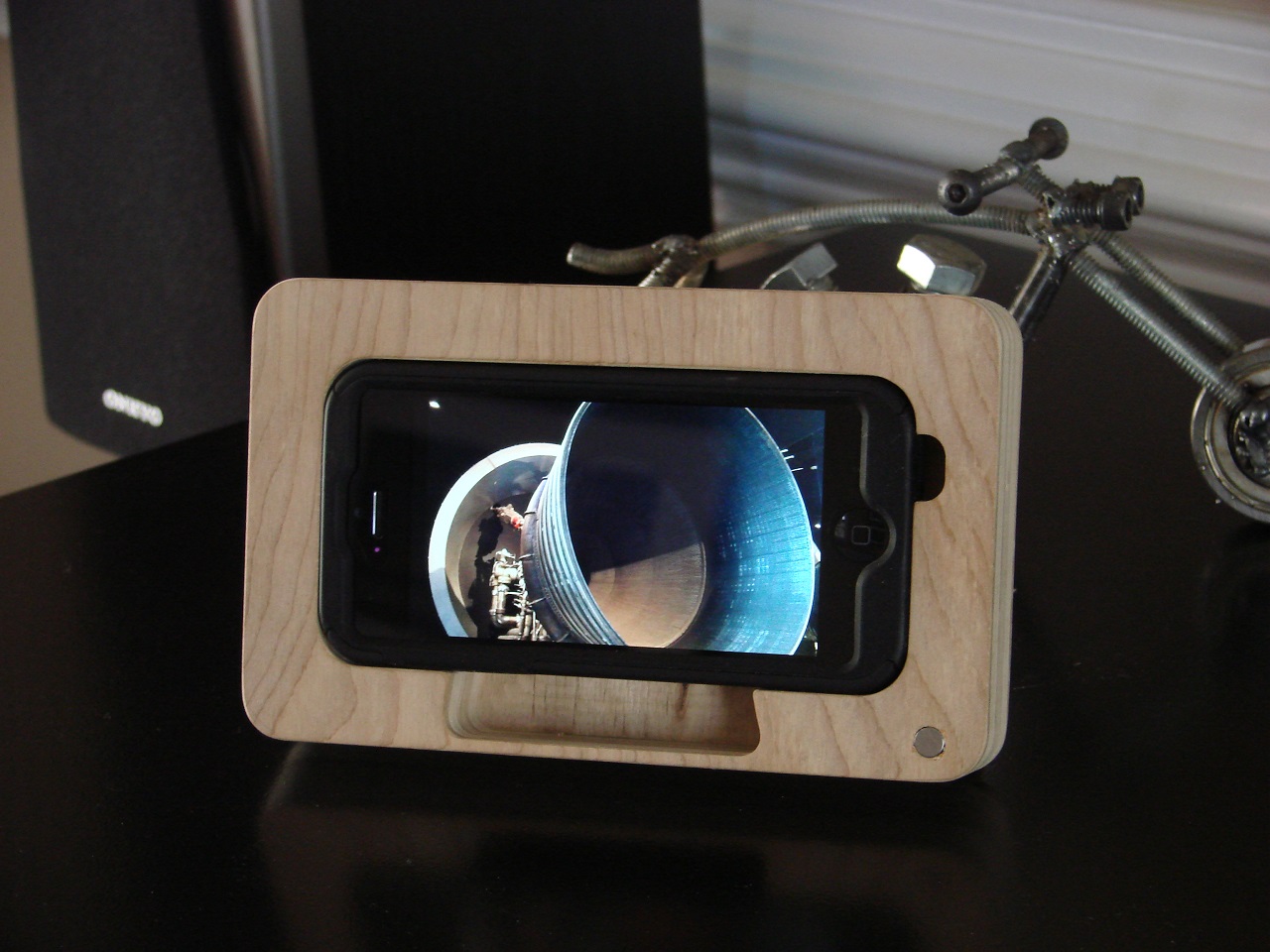
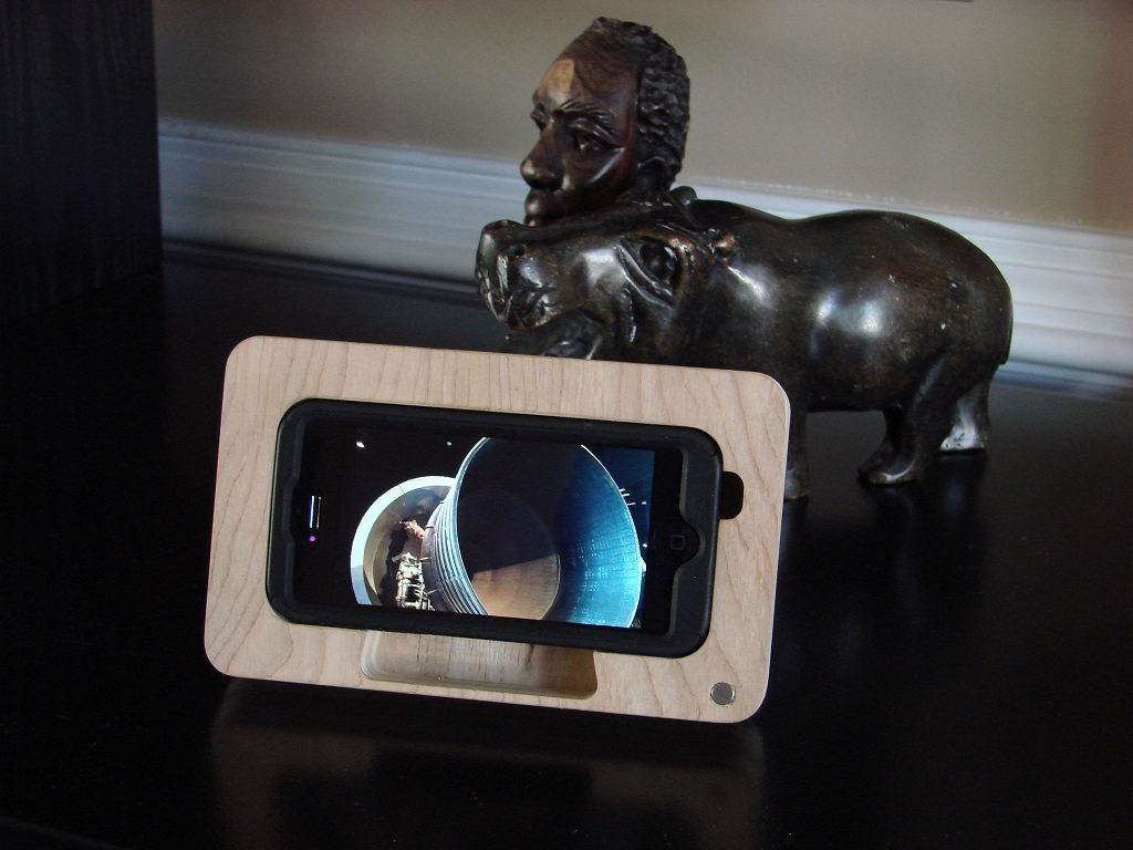
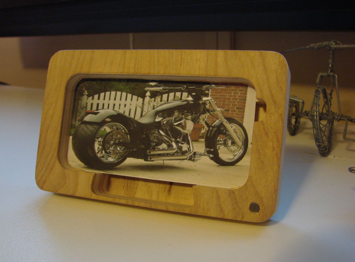
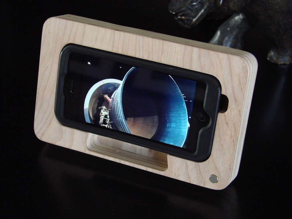
The iPhone SoundFrame was created from a need to watch videos in landscape mode on the iPhone. All iDevices project sound out of the side mounted speaker in a direction at right angles to your ears. You tend to hear more ambient noise than sound from the speaker. There are solutions on the market and other Instructables that detail creation of a passive amplifier for the iPhone to overcome this, but none of them focus on the landscape mode of operation and my personal preference for the sound to be projected from the middle of the device, rather than the right side. Watching videos with a person speaking while standing on the left of the screen and having the sound projecting out of the right is just wrong!
I experimented with a simple layered construction foam model (building on the fly with nothing more than scissors and glue) and was surprised at how effectively the sound could be “bent”. I am no acoustics expert so can’t help you out with the science other than to confirm that sound reflects down the channel and out of the front of the frame. This rough prototype showed that the concept was feasible. The second consideration was the aesthetics – the balance between form and function. Using a 3D Modeling tool allowed multiple iterations before arriving at a final solution without wasting materials and time. An important design aspect was what to do with the SoundFrame when not in use. Designing the frame to have a secondary function as a picture frame provides utility when the iPhone is not present. It also makes a great holder for your iPhone at night if you use your phone as an alarm clock.
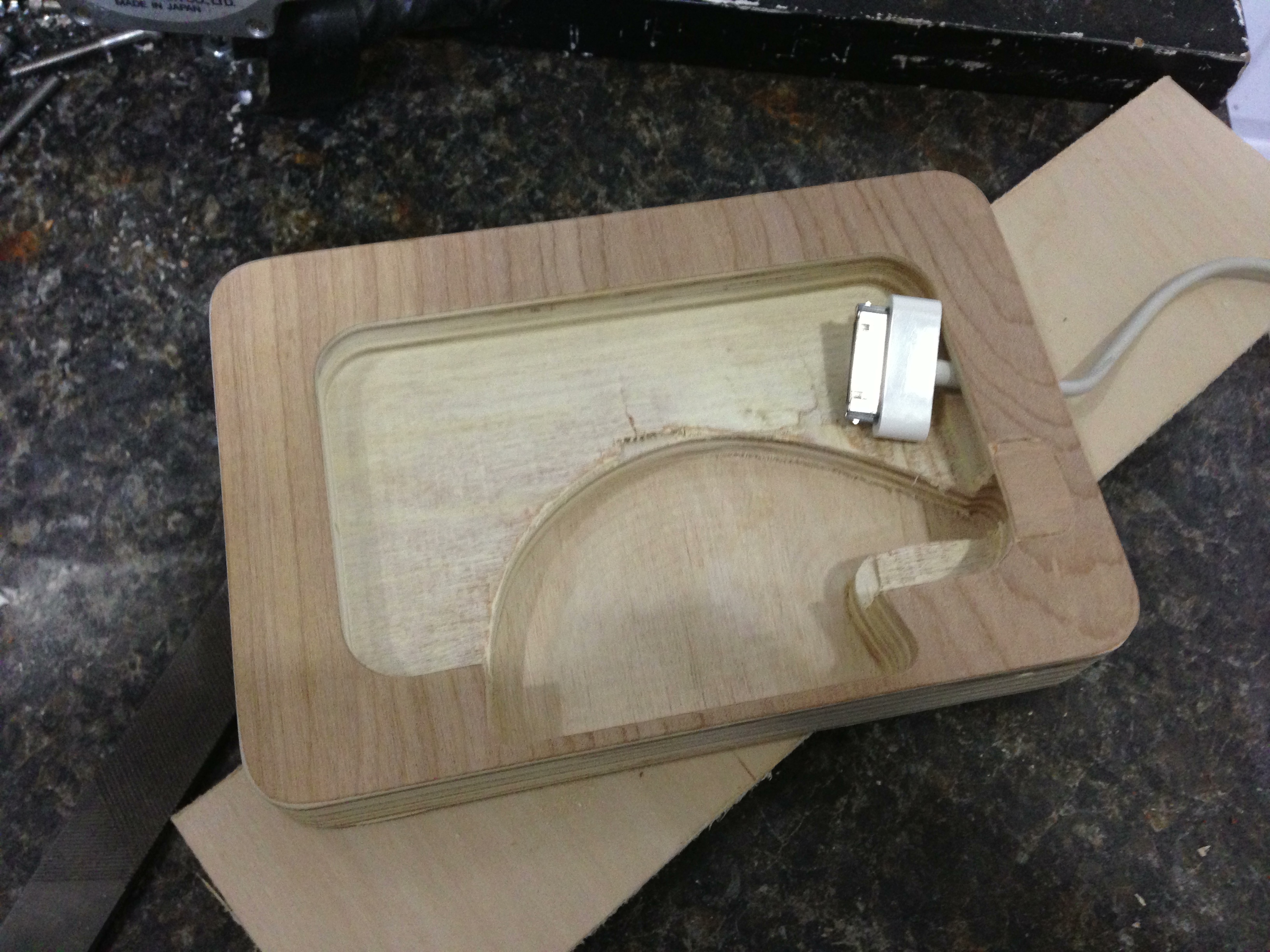
I also made a SoundFrame for the iTouch. For this unit I included a slot in the side for the charging cable and inlaid a thin piece of wood to block the top surface of the sound channel to increase volume even more.
Setting the Scene - the Process
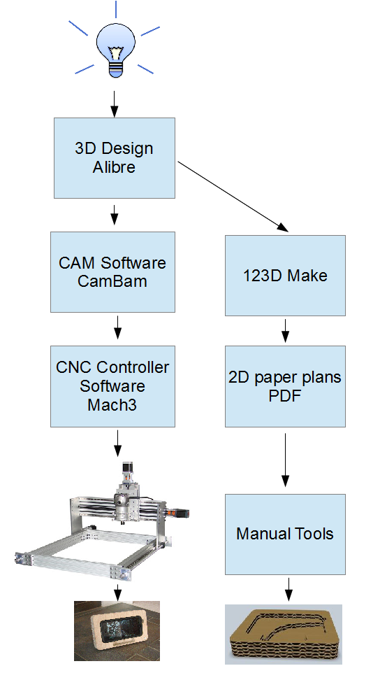
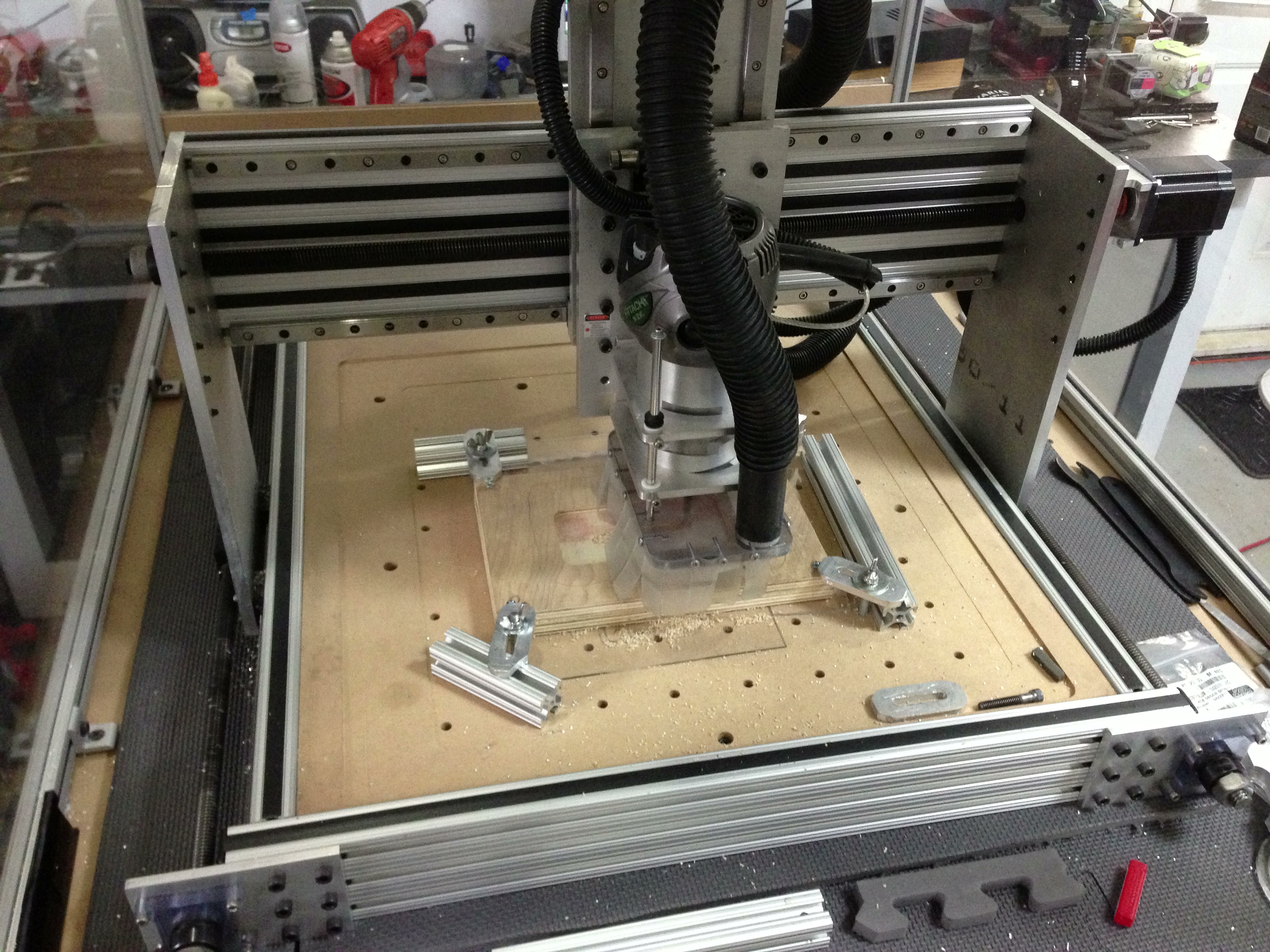
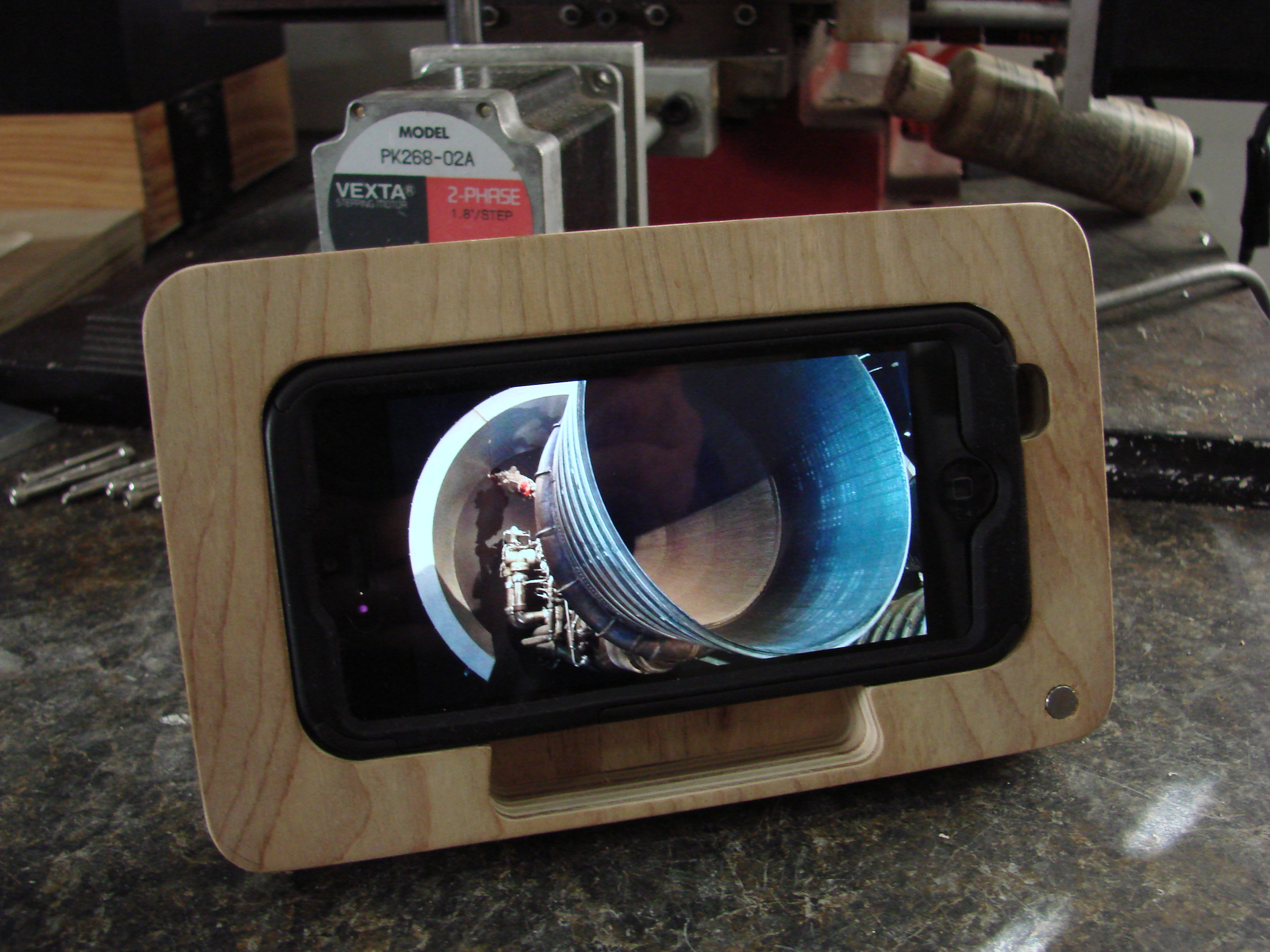
The iSoundFrame was created using Alibre Design Personal Edition software for the 3D modelling, followed by CamBam for converting the design to g-code, which is interpreted by Mach3 Machine Controller software to cut the SoundFrame out of a block of plywood using a CNC Router. The CNC Router was designed and built by me ( construction details here : http://dlsprojects.blogspot.com/ )so it would make little sense to build this tool and then have to resort to hand tools every time I wanted to prototype something. But, given that a CNC Router is not typically available in your home workshop (though through places like TechShop and other hacker spaces, access to these precise and capable machines is easily possible), I will also detail a manual technique using layered construction at the end of this instructable. To do this I used 123D Make Software from Autodesk to slice the model into layers that you can cut out using hand tools. The iPhone SoundFrame is then constructed by gluing the layers together. But first you are going to have to suffer through the CNC method, so here goes!
3D Prototyping
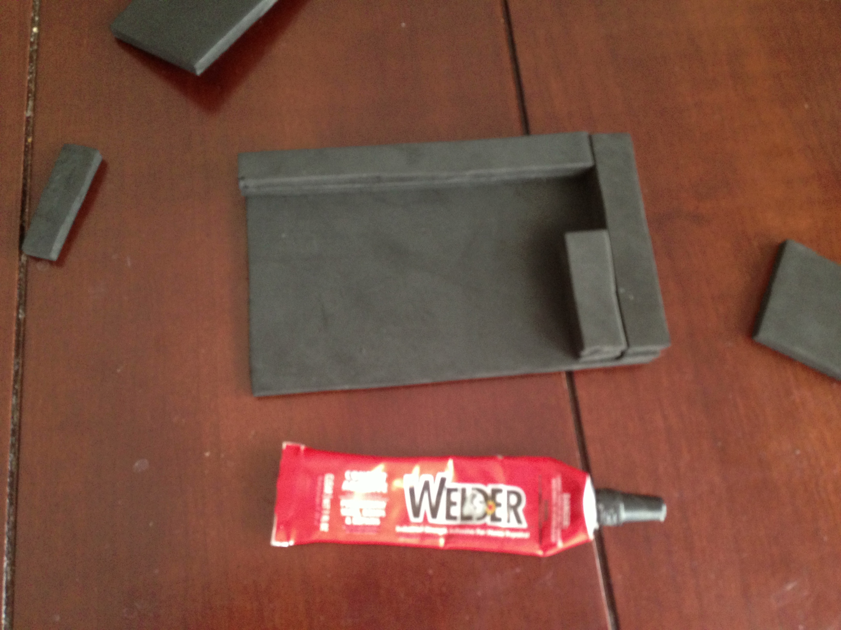
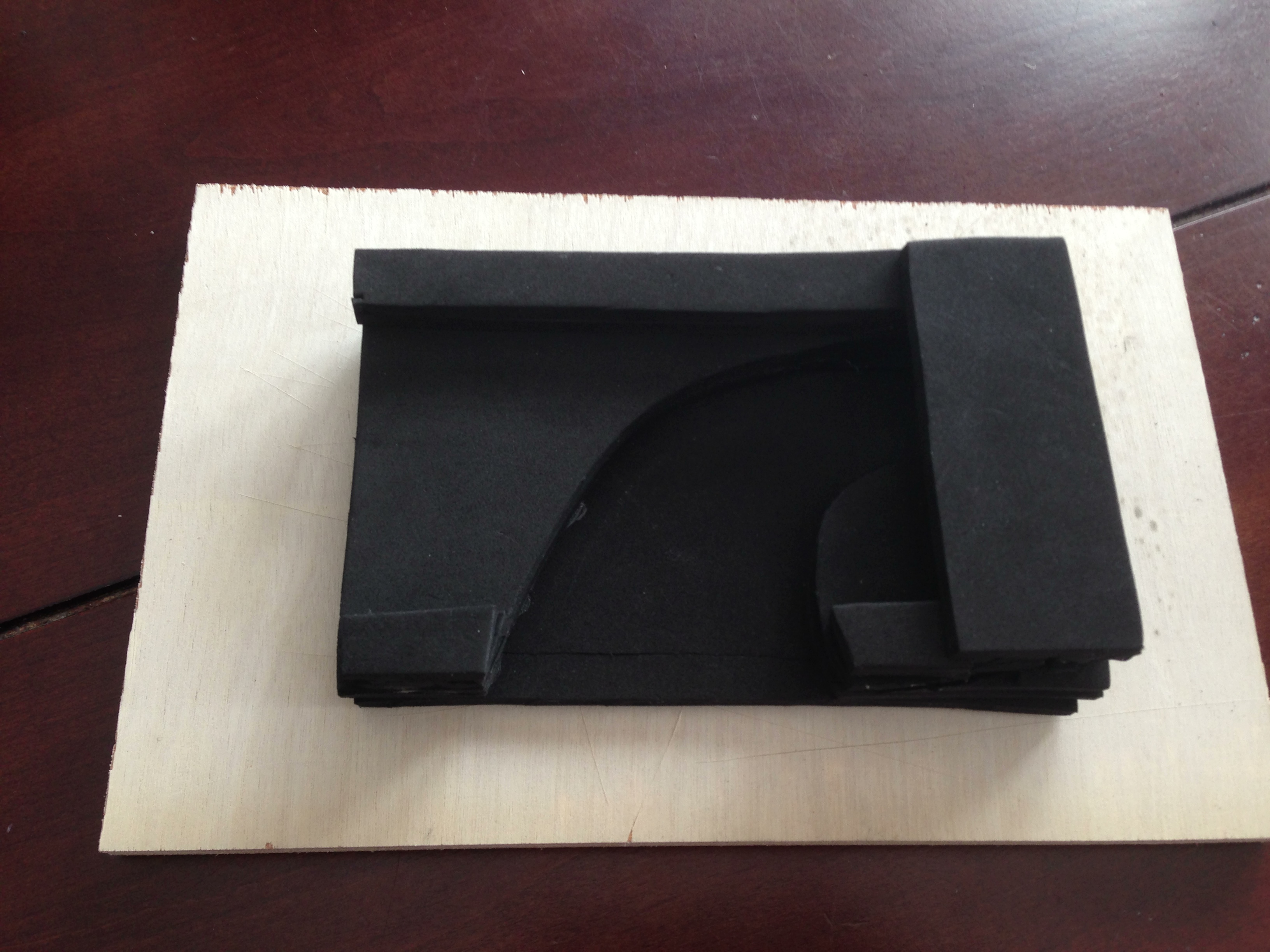
The first step in the process was to create a rough prototype to prove the concept. It is not necessary for you to follow this step. This is just a way to show a quick and dirty prototype technique – a poor man’s 3D printer. My layers are not that precise so the fidelity of the model is poor but proved the concept was feasible – i.e. it is possible to bend the sound from the side of the iPhone so that it projects out of the front and center of the surrounding frame. I used 5mm thick foam sheets from a craft store, a pair of scissors and Welder glue. Rough measurements were taken on the fly and the prototype was pieced together without any real plan... free form if you will.
With proof of concept in hand, it's now time for 3D Modelling, converting the model to g-code and then using a CNC Router to create the part. Once you have the 3D model, you can also create the SoundFrame using other methods like 3D printing or layered construction.
With proof of concept in hand, it's now time for 3D Modelling, converting the model to g-code and then using a CNC Router to create the part. Once you have the 3D model, you can also create the SoundFrame using other methods like 3D printing or layered construction.
3D Modelling Step 1
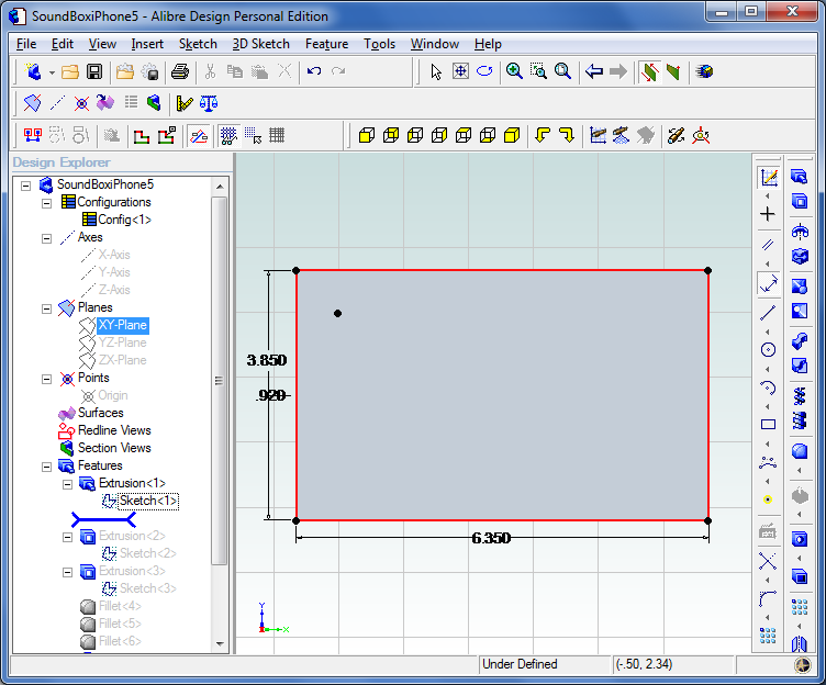
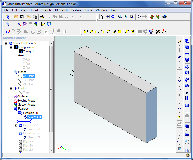
The software I used to create the 3D model is Alibre Design Personal Edition. Any 3D CAD program will work for this. Free ones include - FreeCAD http://www.freecadweb.org/ and Autodesk 123D http://www.123dapp.com/design
To hurry things along, I will only go through the steps of the “final” design. So let's start:
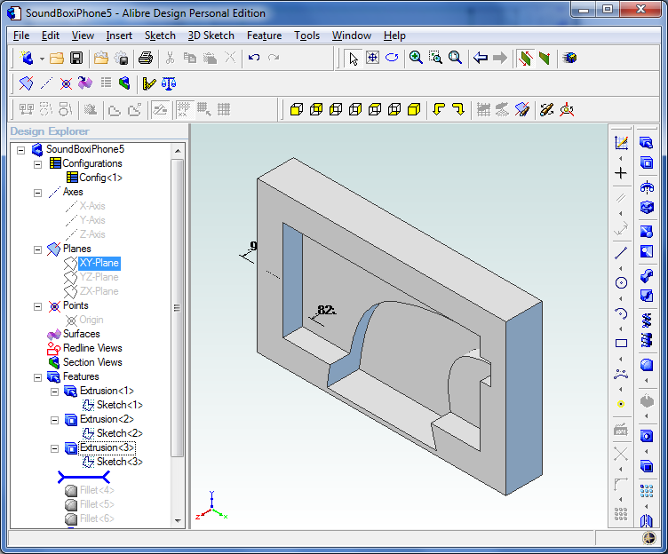
Create a rectangle in the XY plane with dimensions of 6.35 in the x-axis and 3.85 in the y-axis. Then hit the Extrude button to extrude the rectangle to a thickness of .92 inches. The overall thickness is derived from the fact that the raw material consists of two 12mm thick pieces of plywood laminated together (kind of a laminate of laminates). This forms the block of material out of which the SoundFrame is cut using the CNC Router. At this point your model should look like the second image.
3D Modelling Step 2
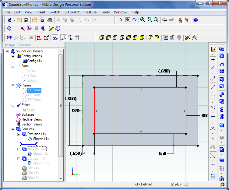
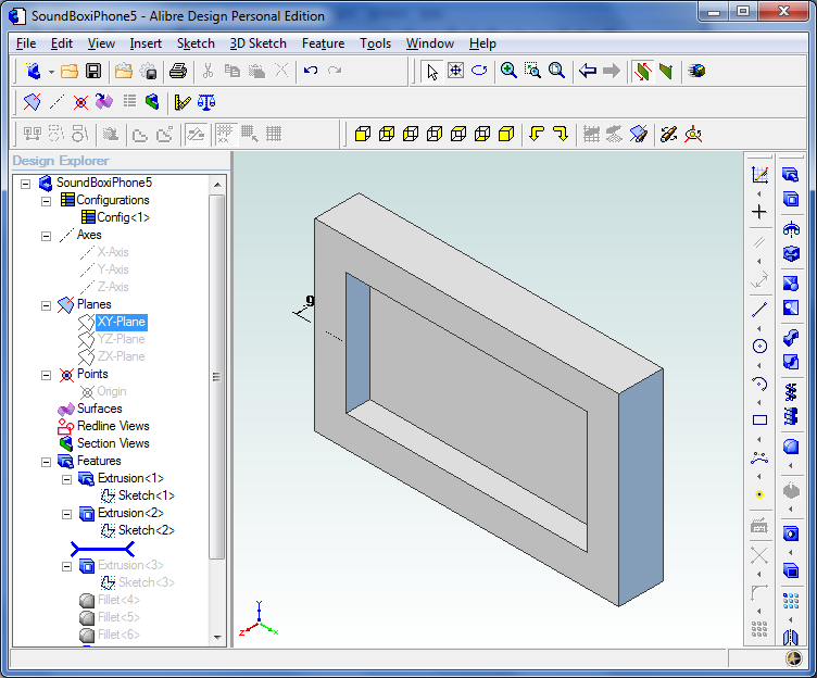
Now clicking on the front surface of the newly created block, create a rectangle 0.65 inches in from each side. This rectangle will be cut downward into the block and will be the pocket that the iPhone rests in. You might need to adjust your dimensions a little here depending on the thickness of your phone case. Basically, the inner rectangle dimensions need to match the outer dimensions of your iPhone in its case. The iPhone 4 for example has different dimensions so you adjust for that by making the inner rectangle match the outline of your phone. Caution – the speaker position of an iPhone 4 is also a little different so the sound capture slot will also need to be adjusted but we will get to that later.
Click the button to Cut a pocket into the block for this new rectangle and set a depth of 0.5 inches which is about the thickness of my iPhone5 in its case.
Click the button to Cut a pocket into the block for this new rectangle and set a depth of 0.5 inches which is about the thickness of my iPhone5 in its case.
3D Modelling Step 3
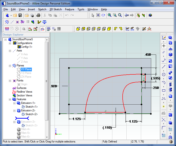
To create the sound channel, another drawing needs to be made on the top surface of the block. I used the Bezier function to create the curved lines. The lines do not need to be exact and I have provided a file for you to use to save you some modeling time. The iPhone sound comes from the speaker on the top right. We curl the sound around the back of the phone and down to exit through an opening in the middle of the SoundFrame. The critical dimension is the position of the sound capture channel with respect to the top edge of the phone. The dimensions I used are shown in the following sketch. Once you're done, "Cut" to a depth of 0.85”. This will give you a sound channel 0.35” deep and the last wood surface to the back of the device is 0.070” thick.
3D Modelling Step 4
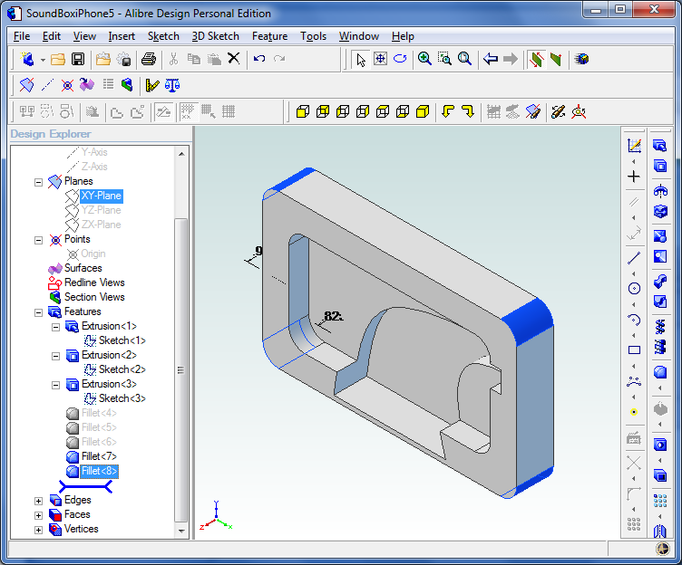
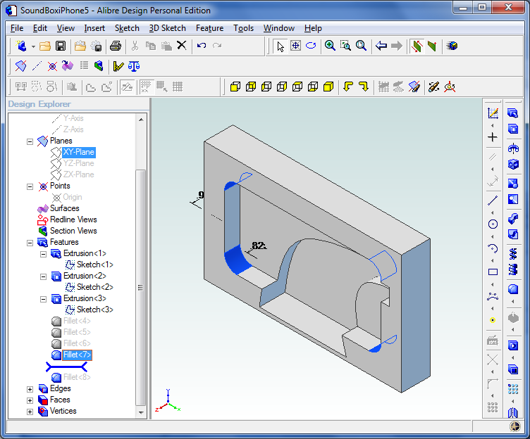
Now all that’s left to do is to Fillet the corners. The outer corners were given a 0.4” radius to mimic the look of the iPhone.
All CNC Routing will be done with a 0.25” end mill, so I added radii to all the corners to see exactly what the part would look after CNC. Remember, the cutting tool radius determines the smallest radius that you can have in a corner. You can have a bigger radius than the cutting tool but not smaller. I did want to smooth the entry from the sound capture area into the main sound channel but that would require a ball end mill or 3D milling (as opposed to 2.5D milling) which with a square end mill would have taken for ever with very fine movements. I found that the square entry works just fine in terms of sound reflection.
I've attached the Alibre V12 file for you to make your own SoundFrame. You need to remove the PDF extension from the file - Instructables would not accept the AD_PRT file.
All right, part is designed…. Now it's time to convert to g-code and manufacture the part on the router.
Downloads
CAM Conversion
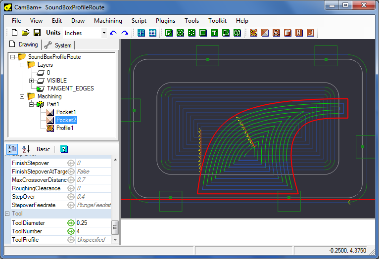
In order to convert the design to a physical part, more data manipulationis required. The first step is to transfer the design to a 2D drawing (I use DXF), import the drawing into a CAM package that will convert the 2D lines into a set of tool paths for the cutting tool, and then convert the tool paths to g-code which is the language that the Mach3 machine controller software understands.
You can also export the design from Alibre as an STL model and then import that into your CAM software to generate a 3D profile. By default, the 3D milling process will machine all surfaces in the model, and depending on the fidelity you need, can generate very lengthy programs. I did a quick estimate for the SoundFrame and with the parameters I chose, the cutting time on my CNC router (25IPM max cutting speed) would have been 14 hours….
It is quicker and easier to export your design as a 2D DXF and then have the CAM software machine each of the lines that you indicate. This will make your processing time are a lot shorter (about 17 minutes in my case) because the resulting machining operations are pocketing and routing, rather than full surface feature milling in 3D.
A pocketing operation will hollow out anything within a closed polygon to the depth you specify. Profiling will follow the outside or inside of a closed polygon – basically scribing a line all the way around the outside or inside, the thickness of the cutting tool.
The software I used to create the g-code is CamBam. I've downloaded a free version from the developer site which allows you to a limited number of fully functional evaluation sessions of the software (40). This makes a really cost effective approach to see if you like the software before you buy it. I think this is a great piece of software for my needs and would definitely consider buying a license for it. http://www.cambam.info/
One of the painfull things about the 2D DXF file import, is that the lines are imported as DXF primitives which results in multiple segments for each line. The CamBam software allows you to select a group of lines and then Join them creating a single poly-line which is easier to work with. The machining of the SoundFrame has 3 operations.
1. Generate a tool path for the inner rectangular pocket to a depth of 0.5”. Use 0.25” end mill and depth increment of 0.25”. This will result in two pocketing passes to get down to the total depth. The Step Over is left at 40% of the tool width. Cutting speed is 25IPM and the Plunge Speed is 10IPM
2. Generate a tool path for the SoundChannel to a depth of 0.85”. Remember, this will start at the top surface. Use 0.25” end mill and depth increment of 0.25”. This will result in four pocketing passes with the final pass 0.1” – the software will automatically adjust to get down to the total depth. The Step Over is left at 40% of the tool width. Cutting speed is 25IPM and the Plunge Speed is 10IPM
3. Generate a tool path around the perimeter of the part to shape the frame and cut it free of the block. We use the same 25IPM and 0.25 depth increment resulting in 4 passes to cut the part free. A nice feature of CamBam is that you can specify Hold Downs. These are areas in the profile routing that it will leave uncut to keep the part in the block. When you remove the part from the CNC Router, you can cut through the Hold Downs with a sharp blade. These hold downs prevent the part from flying loose and during the final profile routing. I made the Hold Downs 0.5” wide by 0.020” high. If you load the attached file, you will see the green blocks which represent the Hold Downs.
4. Now you can use the Menu function to generate g-code for the machine controller. There is software available that will simulate the cutting in 3D. This is useful because it is easy to make a mistake which will result in a cut you did not expect destroying your part. The simulator will show you the mistakes before you ruin your work-piece! Common mistake is to set the wrong final depth or cut increment which can break your tool, wreck you surface table etc. The simulator is a money savor but an expensive tool. I downloaded trial of CutViewer for this and corrected my mistakes…. Cutviewer is good for one month after which you have to pay.
I've attached the CamBam file for you to make your own SoundFrame. Please note you need to remove the .pdf extension - CamBam uses the.cb extension (workaround for the instructables uploader).
Next we will prepare the wood, CNC machine and get cutting.
Downloads
Cutting the Part
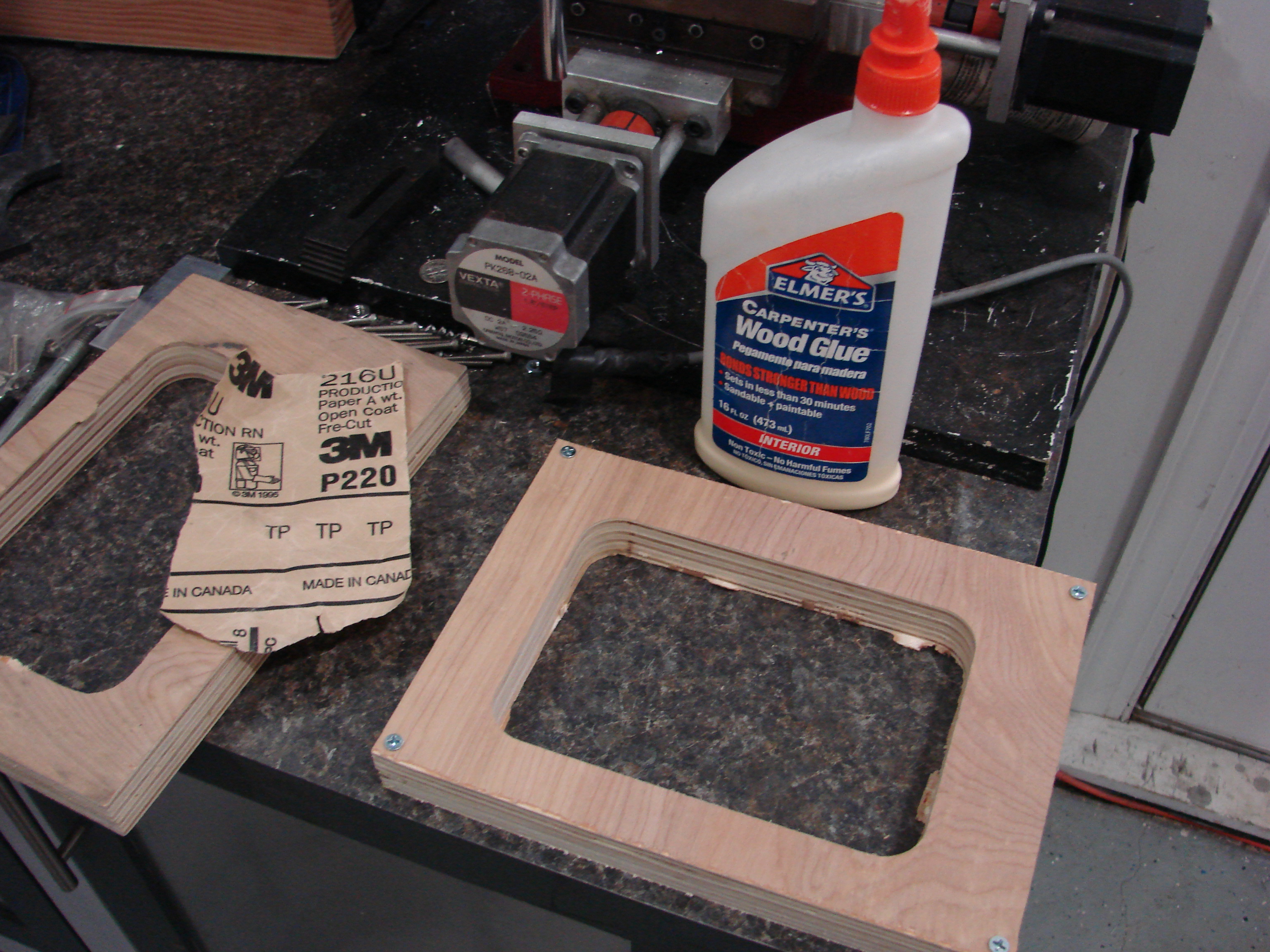

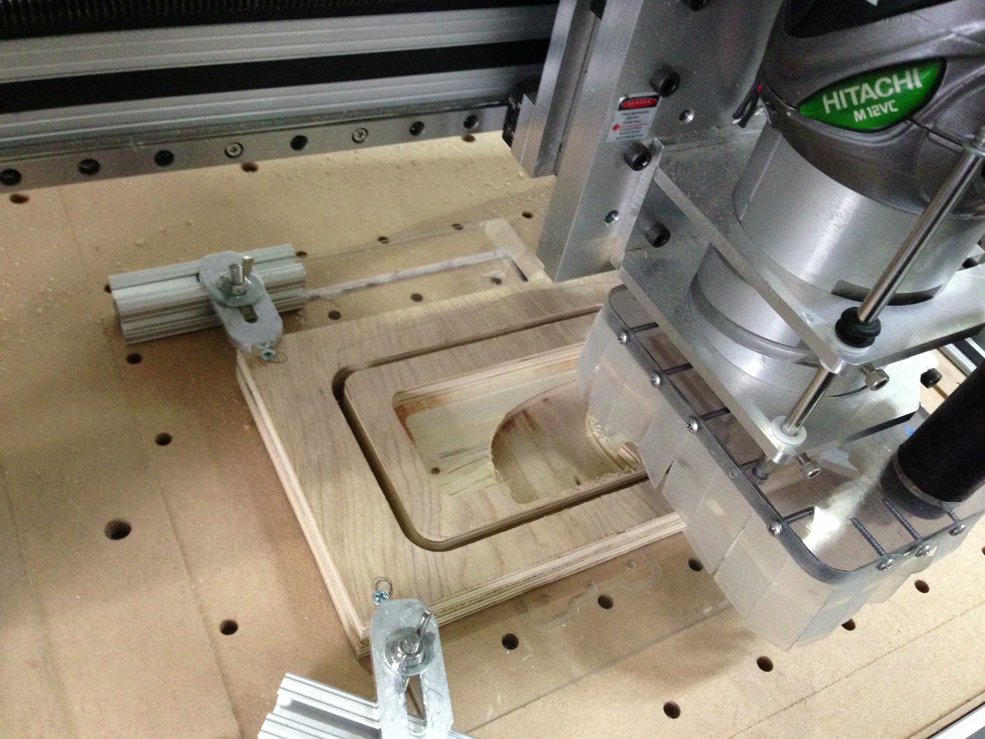
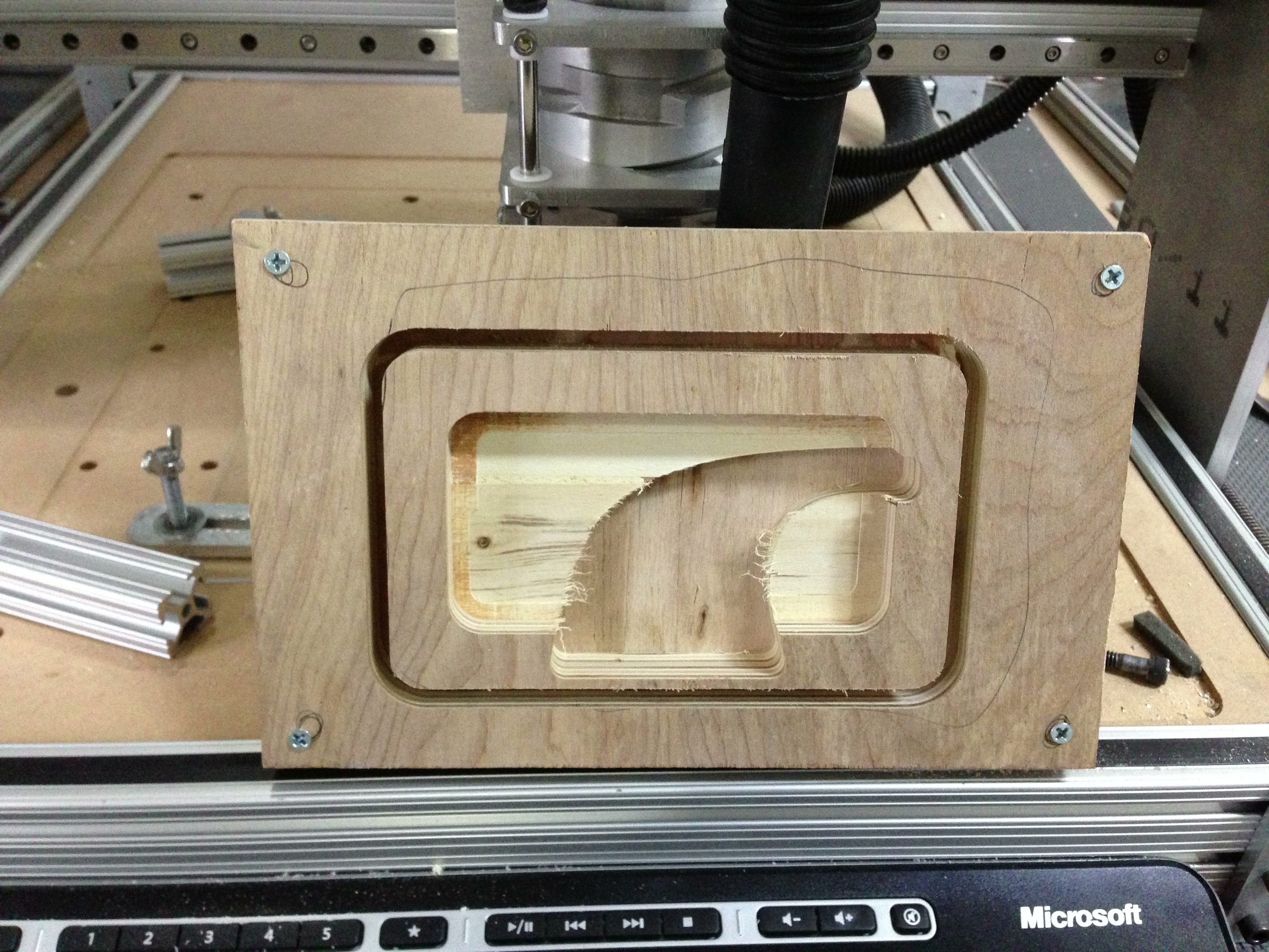
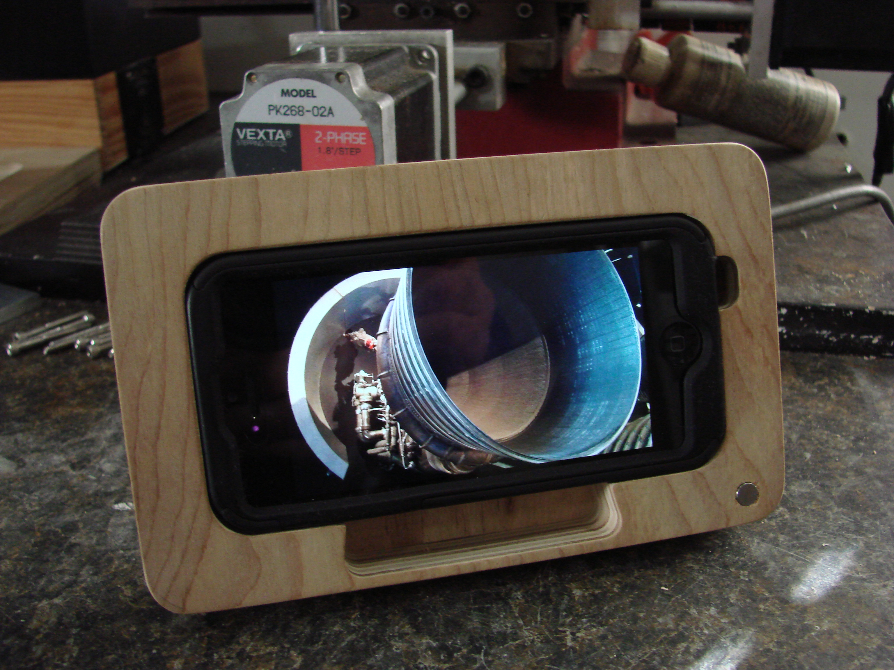
Use two 9”x5”x12mm (230mm x 127mm x 12mm to avoid mixing english and metric units!) and glue them together with Elmers wood glue. In each corner, screw a #6x3/4 wood screw to clamp the parts together while drying. I forgot to take pictures while I was doing this so I have a picture after the part was cut out of the wood. Use your imagination to fill the inside!
After allowing following the Elmer guidelines for the glue to set (about 1/2 hour), load the wood into the CNC router and fasten to the cutting table using whatever clamping system you have. Be sure to orient the wood so that the long direction points in your positive X direction and the short direction in your positive Y direction. Position the cutter so that your zero position is about 0.5” in from the edge of the wood. I have my router set up with X axis running from left to right, and Y running from front to back. Z runs up and down in the vertical plane. Load the g-code file into your machine control software, startup the router and let rip.
I've attached the g-code file. Please note you need to remove the .pdf extension - Mach3 should use the .nc file extension although it's not really picky about this! (workaround for the instructables uploader).
After about 17 minutes you should have something similar to the 4th picture. Using a sharp knife, carefully cut through the hold downs and free the part. Using sandpaper, smooth the part and you are done. On the right corner I drilled a hole through which a 1/4" steel rod is pressed to create a stand to allow the unit to tilt back at an angle. The hole should be place higher up closer to the center of gravity, but that forces the rod to stick out further.
The sound performance is surprisingly good. By redirecting the sound in the general direction of the listener, the volume is higher. Having the sound come out of the middle of the frame is great for videos.
The next step was to try a SoundFrame for the iTouch.
Downloads
And One for the ITouch
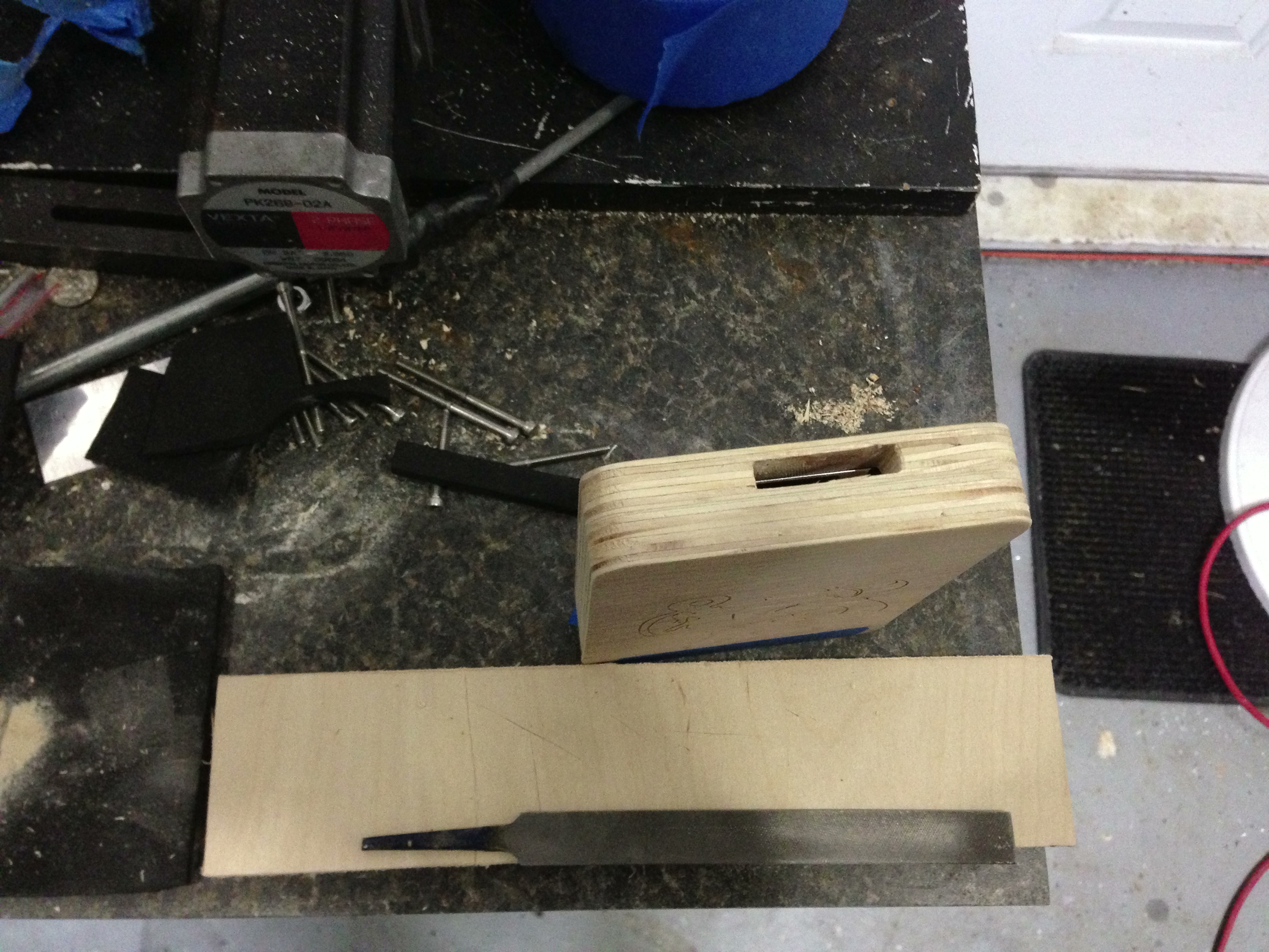
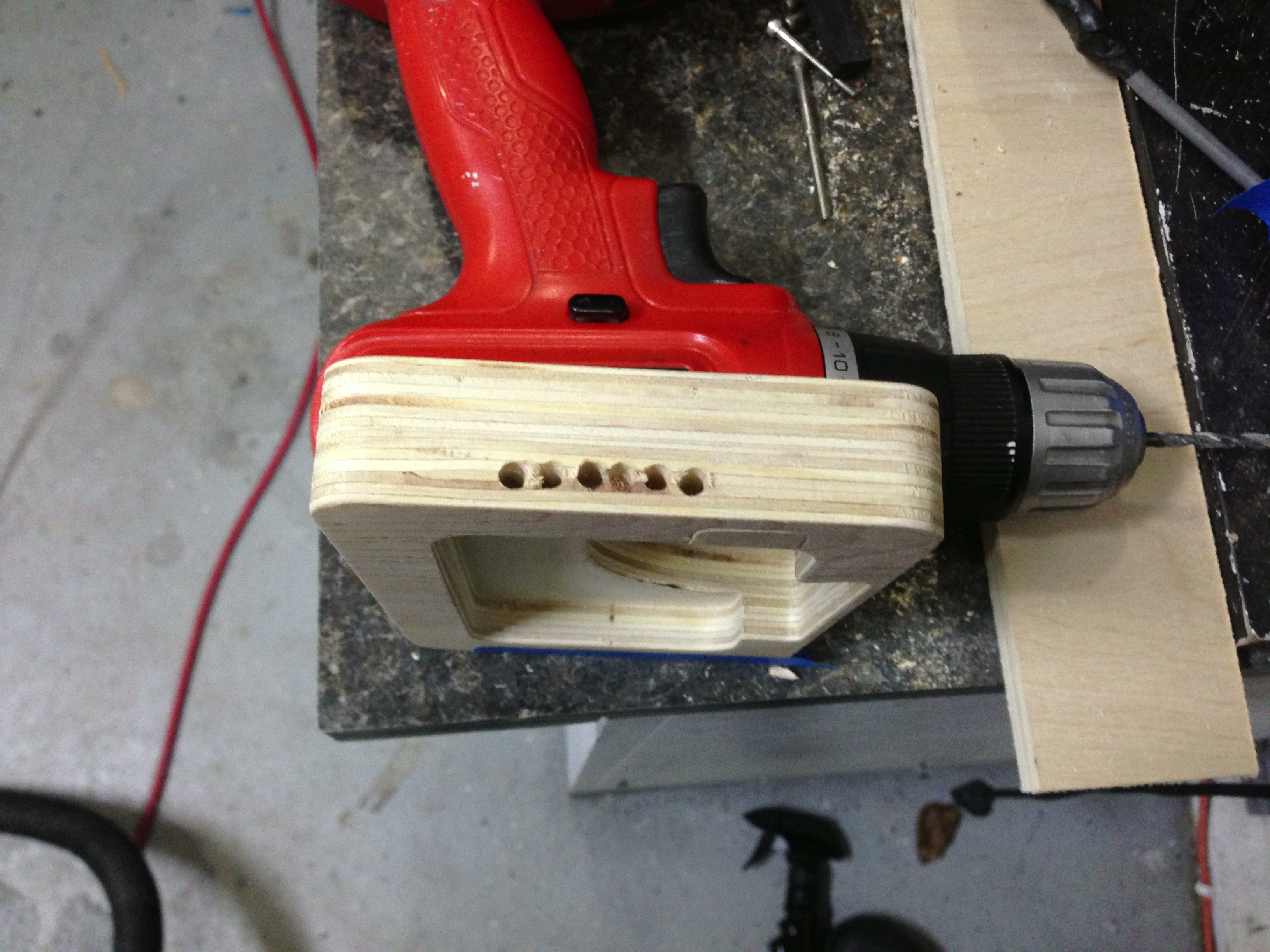

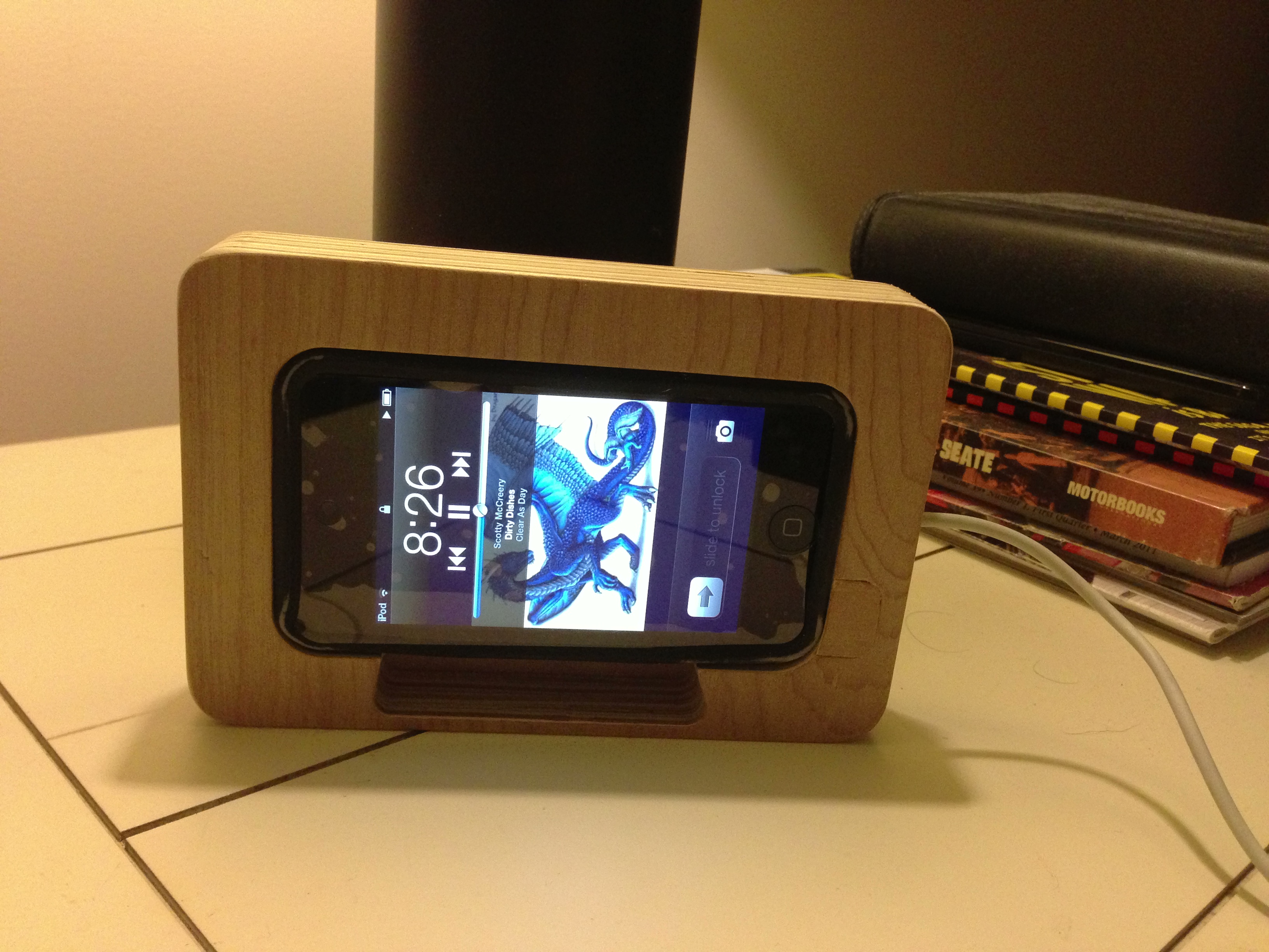
By adjusting the outside and inner rectangle dimensions as detailed in previous steps, a frame for any iDevice can be made. I adjusted the dimensions in Alibre and produced a frame for the iTouch. This version also had a slot so that the iTouch can be powered while it is in the frame. To make the slot, drill a number of 1/8” holes. Connect two or three of the holes using sideways force on the drill to allow for a blade to pass though the enlarged hole and connect the remainder of the holes. Eventually the slot was finished off using a flat file to get the final thickness and width. This was trial and error until the connector fitted properly.
Again, performance is very good. The happy recipient has been using this on a daily basis. As promised, I'll now briefly show you how to make one without a CNC - so read on!
Again, performance is very good. The happy recipient has been using this on a daily basis. As promised, I'll now briefly show you how to make one without a CNC - so read on!
ISoundFrame Stacked Slices - 1
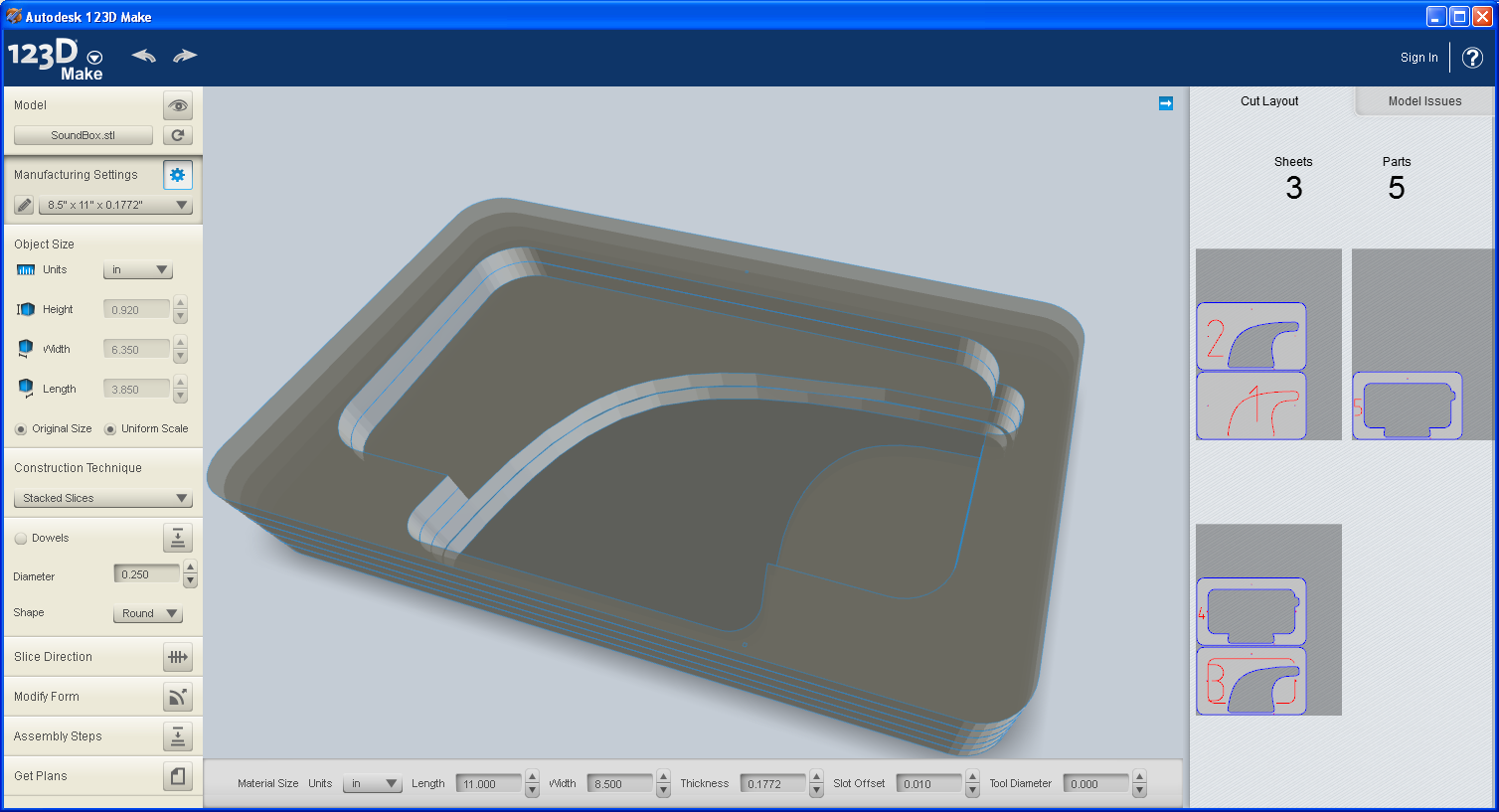
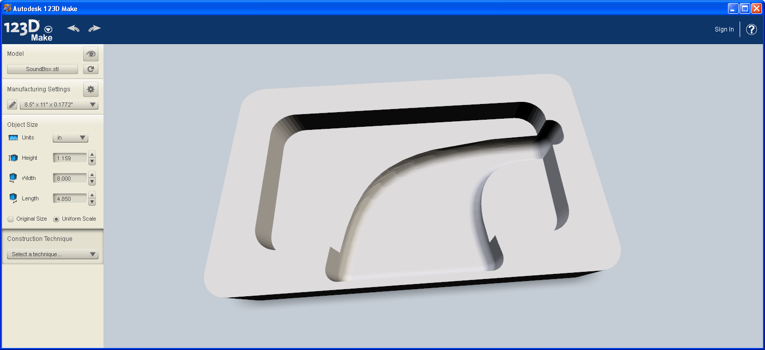
Download and install 123D Make software from http://www.123dapp.com/make
The browser based app does not support export of the result files in anything other than EPS. The PC based software allows exporting as PDF and DXF in addition to EPS. We will be exporting to PDF for this example so installing the software on your PC is required.
We will be using 123D Make to make a SoundFrame using the “Stacked Slices” method out of cardboard.
After installation Import the SoundBox.stl model into 123DMake.
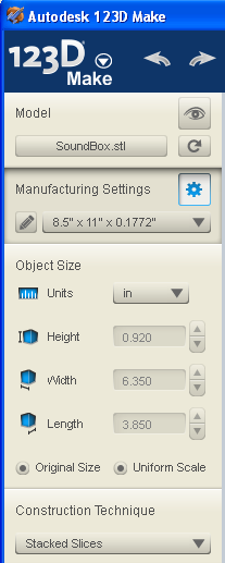
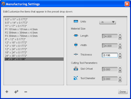
Set the Manufacturing Settings to 8.5”x11”x0.1772”.
Set the Construction Technique to Stacked Slices. The software will slice the model into 5 parts. Make sure to click “Original Size” otherwise the part will be scaled and not fit your iPhone…
Downloads
Stacked Slices - 2
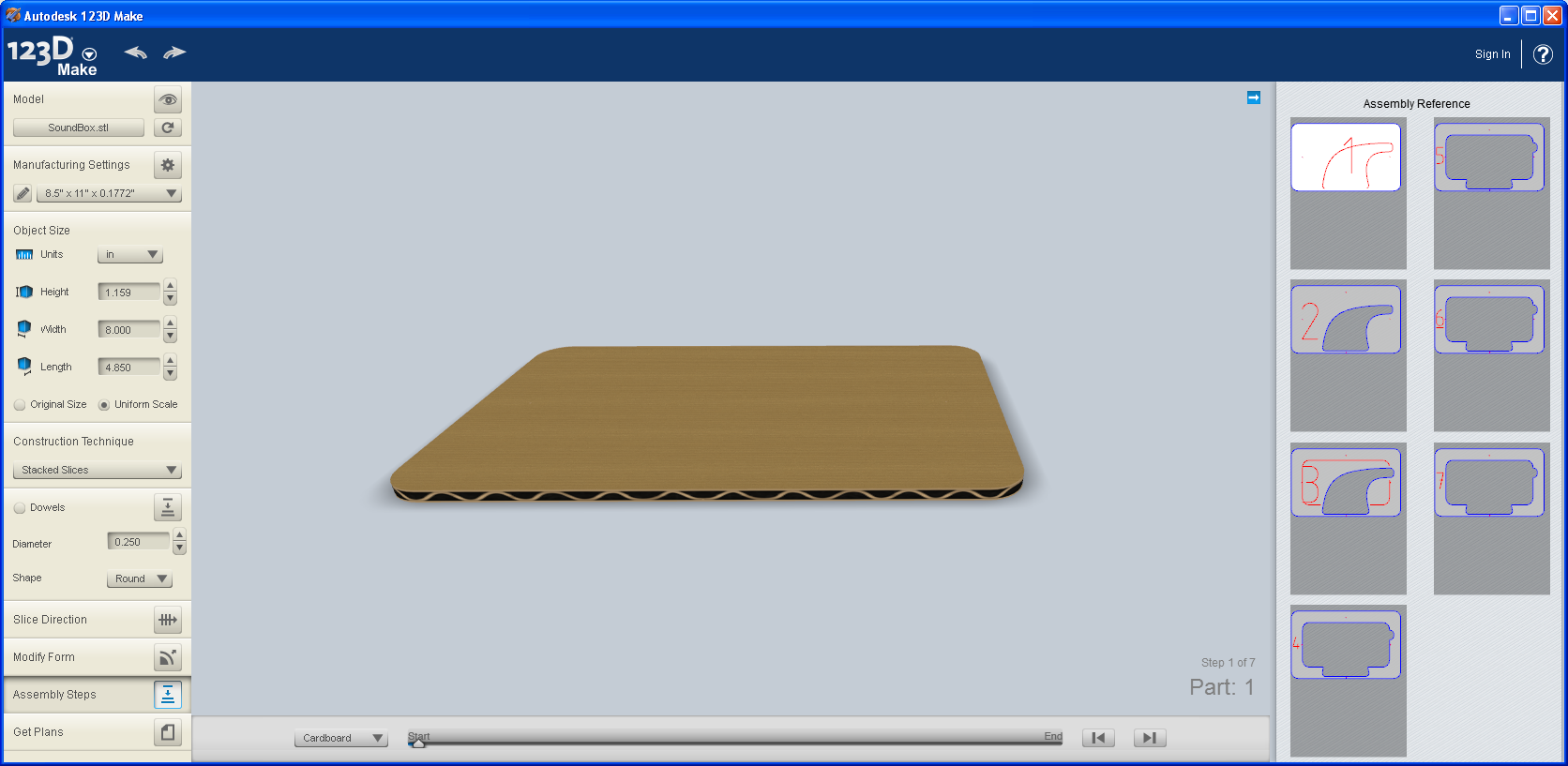
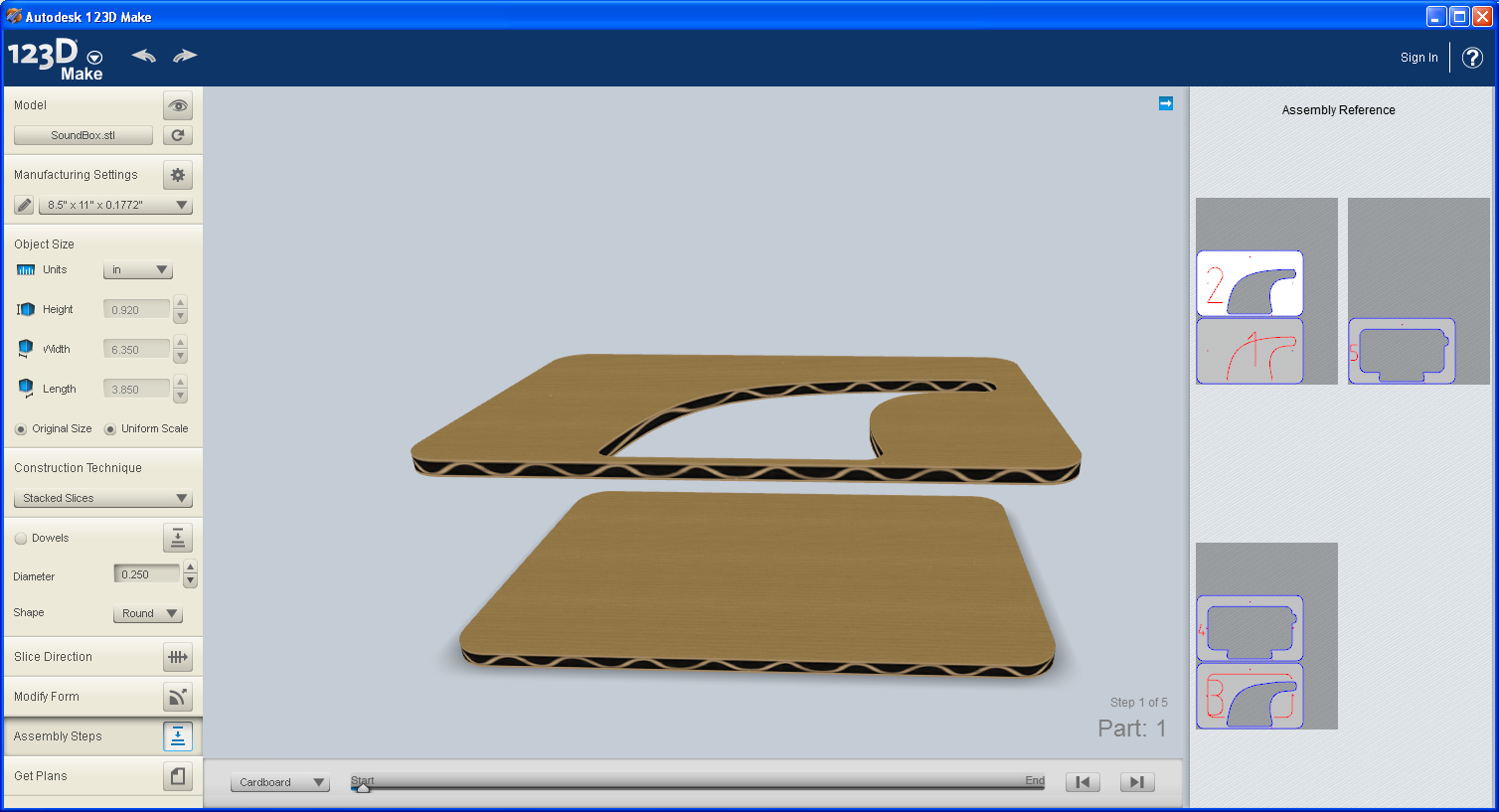
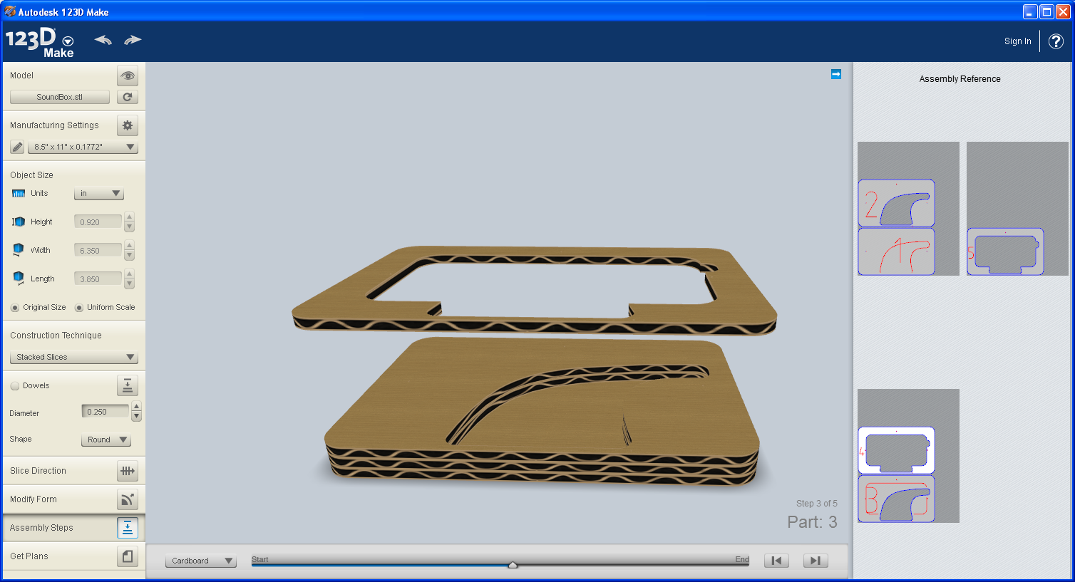
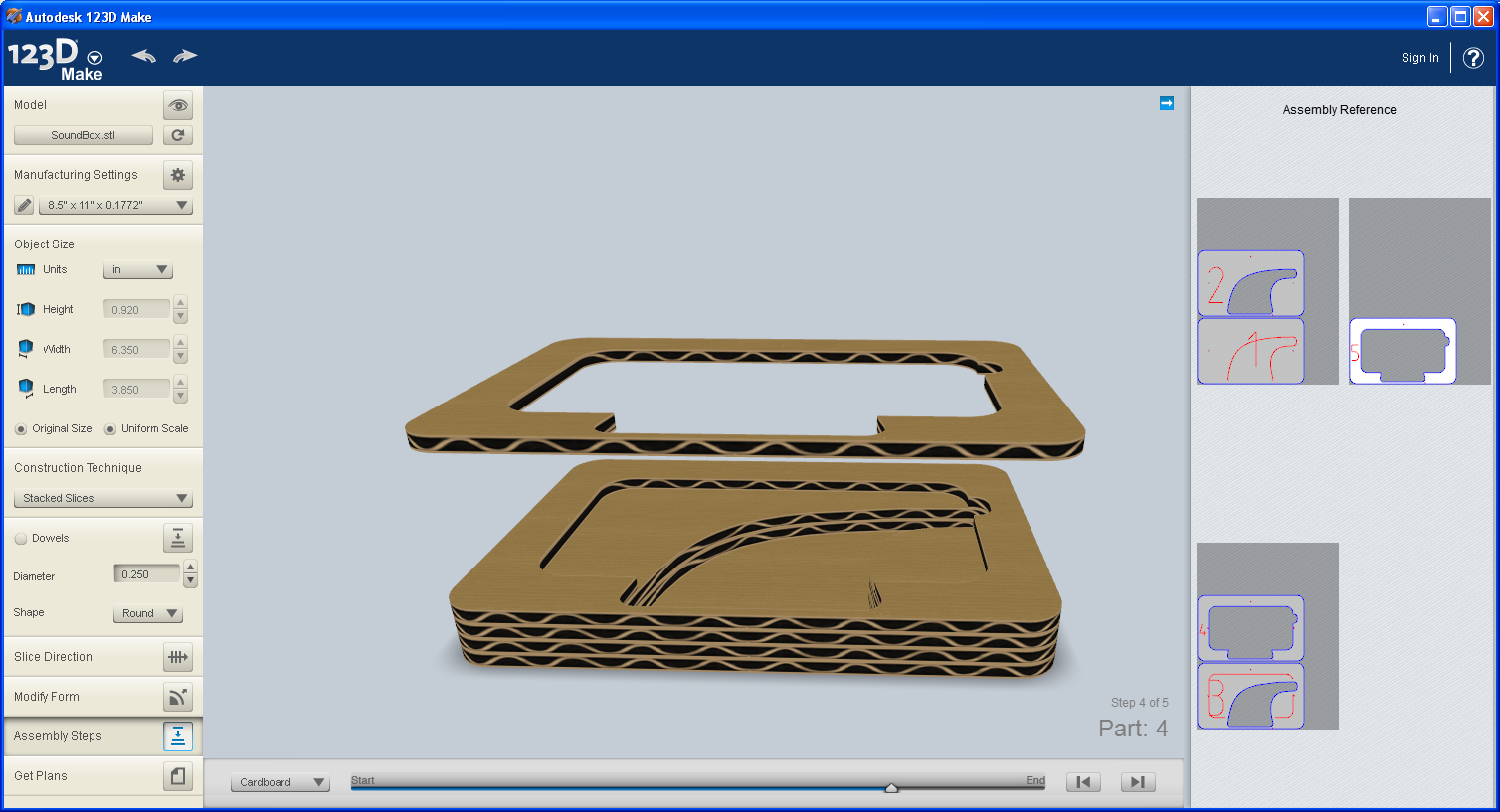
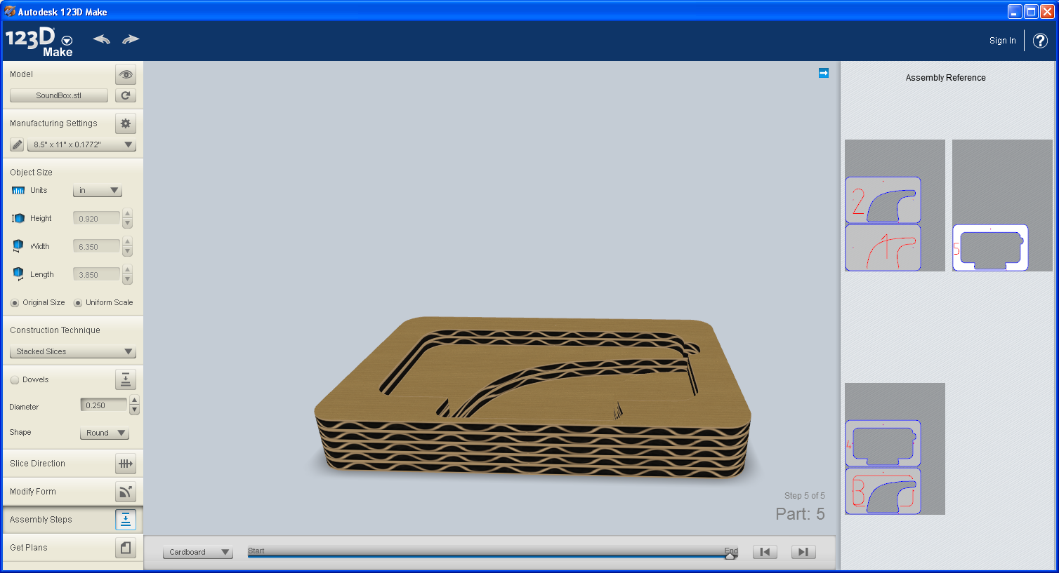
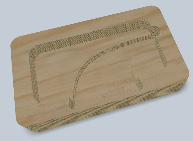
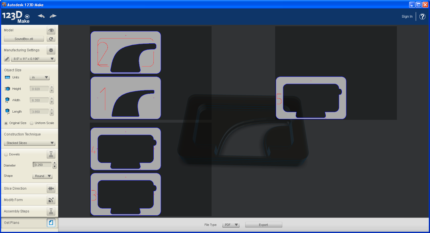
Click the Assembly Steps button on the left and the part will be displayed in the default material which is Cardboard. The timebar on the bottom can be dragged to show the different assembly steps. Notice that the thickness will be different to the original 3D design because of the discrete layer thickness of the material you choose for construction. You can make extra layers and glue them to fit to get things adjusted to your liking.
This software slices the 3D model automagically. This is the way software should be.
You can change the material type to Plywood or plastic. The 123D Make software does a great job of presenting the raw material in a realistic way so you can get a good feel for your final product.
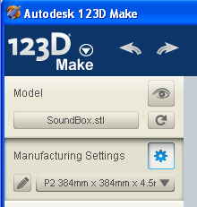
You can experiment with the manufacturing settings to get the sheet material settings to match what is available to you. At Lowes for example, 5mm Luan plywood is easily available. Add a custom manufacturing setting for this by clicking the Pencil icon in the Manufacturing settings group.
Use the "Get Plans" button to export the layers to a PDF file and print them out on your home printer. I've attached the plans I used for the iPhone 5 in Incipio Case to this step.
Downloads
Stacked Slices - Step 3
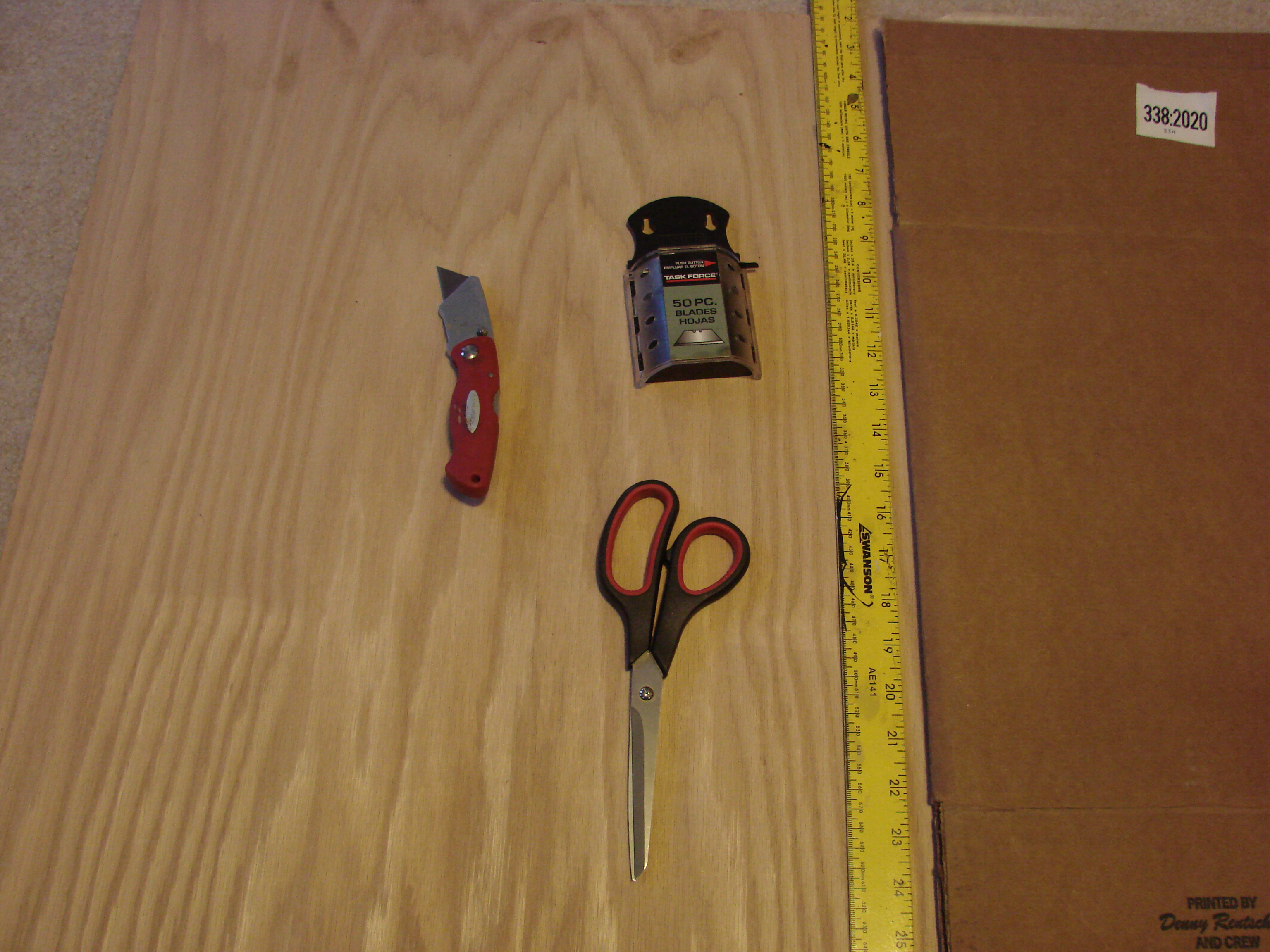
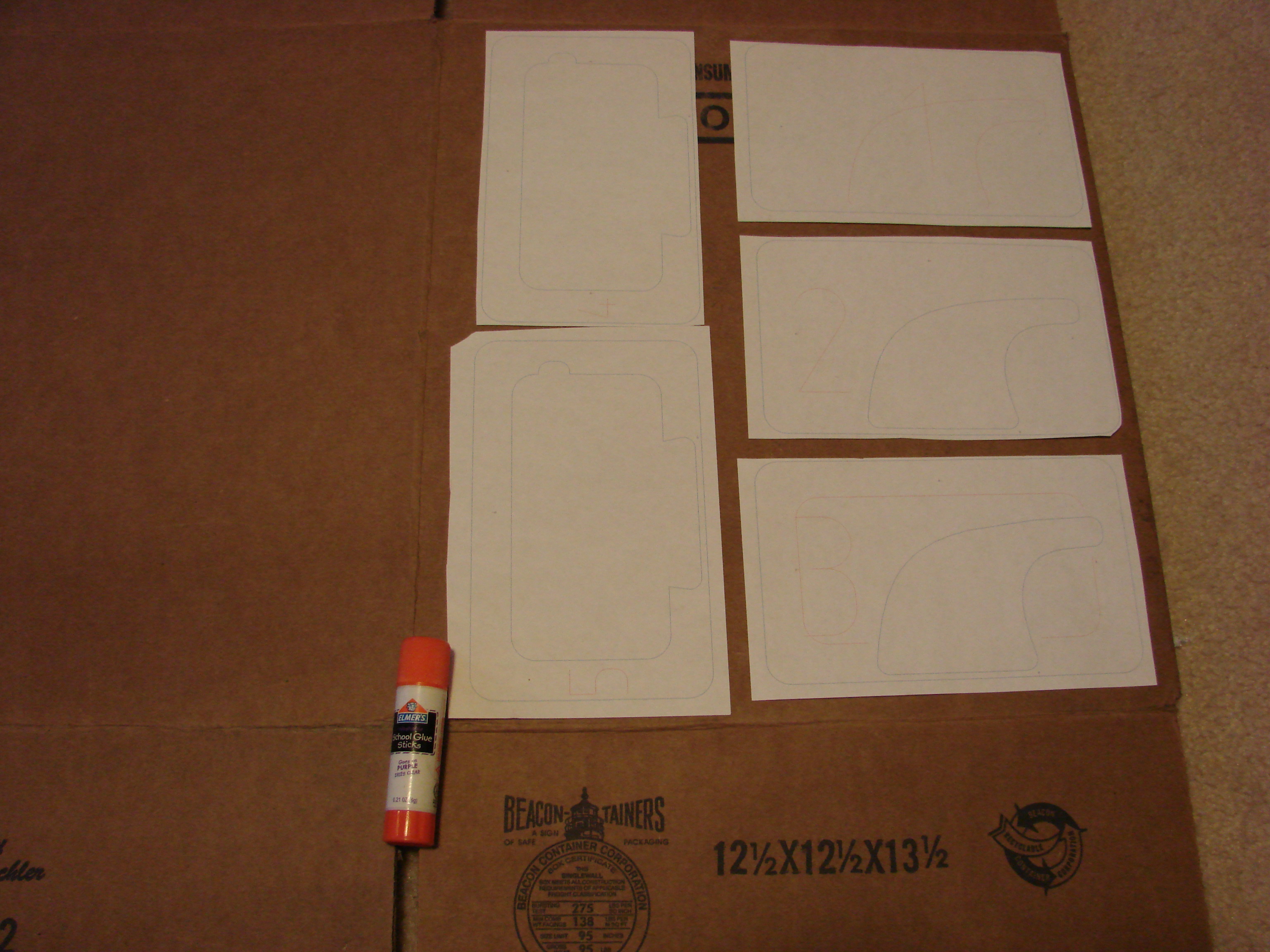
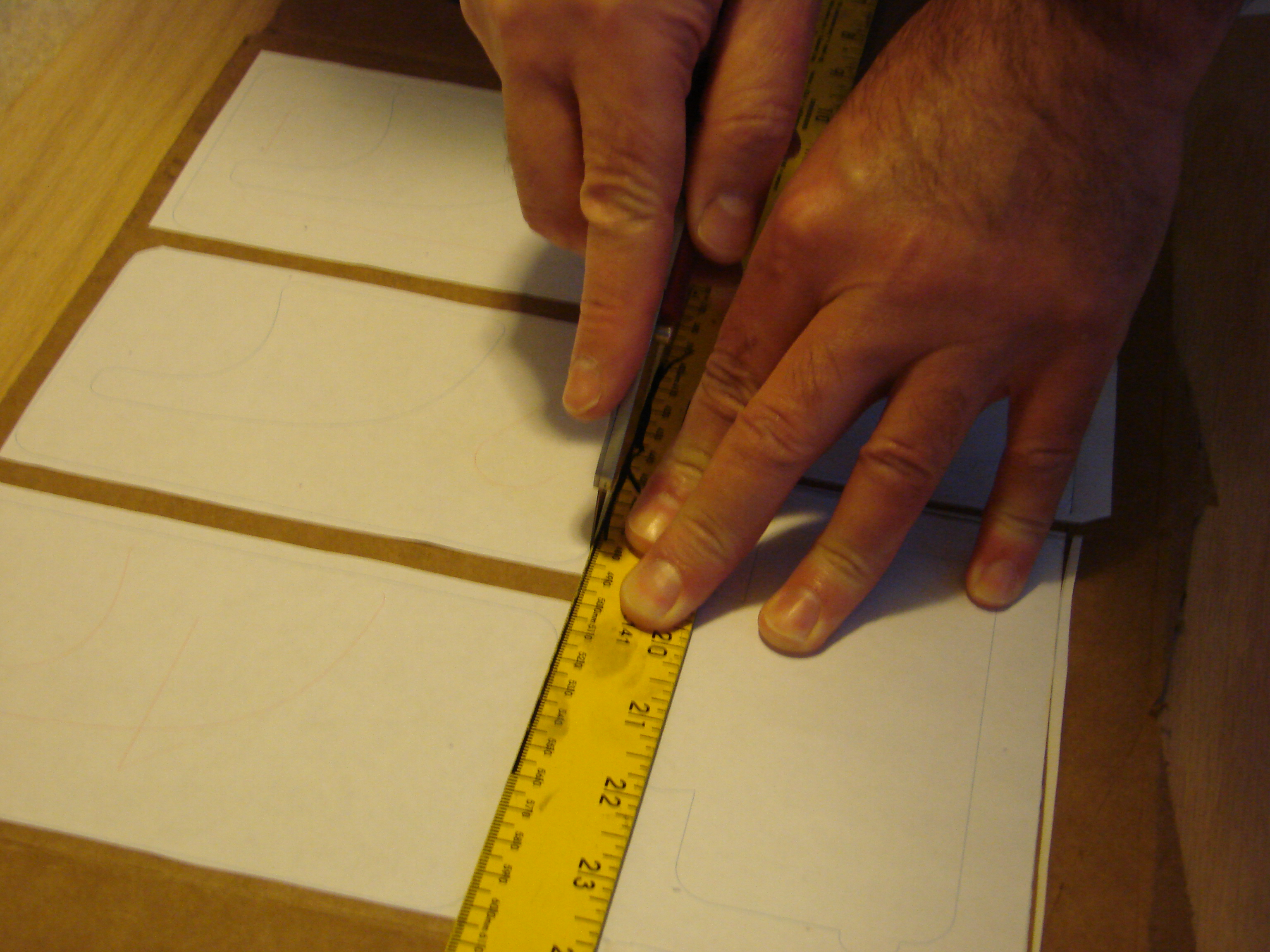
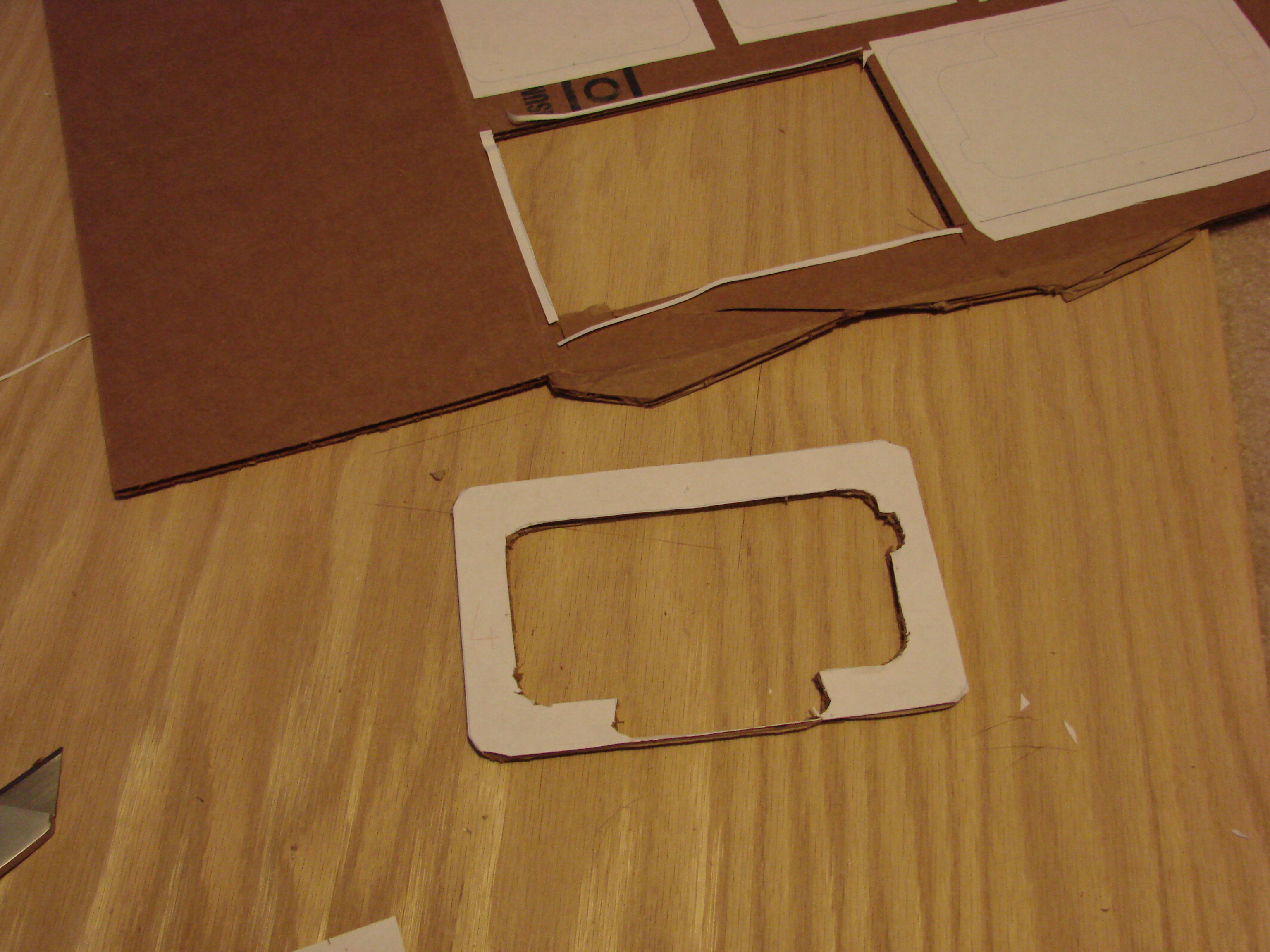
To make the stacked slices SoundFrame, print the individual parts onto paper. Then cut each of the parts out of the paper sheets and then glue them to the cardboard. Then cut each of the parts out of the cardboard using a sharp knife. When all the parts are free, glue them together to make the cardboard SoundFrame. I only cut out one part to demonstrate - since I have a nice CNC cut frame.... my work is done!
I have had plenty of use out of my SoundFrame. I hope you do to!
I have had plenty of use out of my SoundFrame. I hope you do to!