Fischertechnik LED Reaction Time Game
by ftking_83702 in Circuits > LEDs
3725 Views, 2 Favorites, 0 Comments
Fischertechnik LED Reaction Time Game


How to create the fischertechnik LED REACTION TIME GAME
I play with different educational manipulatives for a living. (Visit www.weirdrichard.com).
An easy-to-build application is the LED REACTION TIME GAME. The robotic controller (in this case the PCS BRAIN) beeps and lights up the first LED as a warning and after a random amount of time will light the second LED. As soon as the second LED is lit, the player will tap the push button sensor. The software will display the amount of time it takes to respond to the light!
This instructable will describe how to create a fischertechnik LED REACTION TIME GAME.
Note: The images were generated by a CAD program and a fischertechnik elements library.
Gather Elements:

You will need to gather your elements. The fischertechnik elements are available from a range of kits available from ebay, Craig's List, or fischertechnik retailers.
Elements can be purchased individually from a variety of sources including www.fischertechnik.de.
The PCS BRAIN and electronic components can be purchased here:
http://edventures.com/imssc/nsimssc/index.php?&pid=12182
The PCS BRAIN kit can be purchased in Germany here:
http://www.nwt-online.de/products_new.php?osCsid=16227515cbca6245b6280bbfacf08079
OR similar robotic controllers and components can be purchased elsewhere.
The Parts List:
2 LED elements
3 Small Nuts
3 Sensor Leashes
1 Switch
3 Bolt
1 Angular Block 60 Degrees
3 Building Block 15 with Counterbore
2 Building Block 30
3 Building Block 15
1 Base Plate 120x60
1 PCS BRAIN
Blocks on the Base Plate

Insert a Building Block 15 into the fifth and ninth slots of a Base Plate 120x60. Place the blocks so that they are flush with the near side of the Base Plate.
Touch Sensor


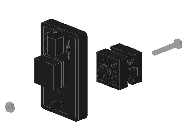
Mount a touch sensor on a Building Block 15 with Counterbore using a small nut and bolt. Insert the assembly between the two Building Block 15s. Insert the assembly between the two Building Block 15s.
Blocks on the Base Plate


Insert a Angle Block 60 onto a Building Block 30. Insert the assembly into the seventh slot (from the left) on the far side of the Base Plate.
LED Assembly


Mount two LEDs on Building Block 15 with Counterbores using small nuts and bolts.
In order, connect a Building Block 15, LED assembly, Building Block 30, and LED assembly.
In order, connect a Building Block 15, LED assembly, Building Block 30, and LED assembly.
Add LED Assembly

Mount the complete LED assembly to the Angle Block 60.
Your LED REACTION TIME GAME is finished! All that is left is to program the game and play!
Your LED REACTION TIME GAME is finished! All that is left is to program the game and play!
Plug In, Program, and Play


I used the PCS Visual Logo in the CORTEX PROGRAMMING environment.
I took screen captures so that the program can be replicated.
Download your program, and hook up the LEDs and Touch Sensor to the appropriate ports!
Video of game play:
https://www.youtube.com/watch?v=8lUZmis65jk
I took screen captures so that the program can be replicated.
Download your program, and hook up the LEDs and Touch Sensor to the appropriate ports!
Video of game play:
https://www.youtube.com/watch?v=8lUZmis65jk