Zoom Control Box
BREAKING NEWS (September 2021):My Bluetooth version is now live!
Before the pandemic few of us had even heard of Zoom. Now it's a part of our daily lives for many of us.
If you're just joining other people's meetings, it's easy. Surely, one of the reasons it's caught on. But another reason is that it's actually quite powerful. Once you start using it to the full for your own meetings you can share your screen, presentations, music and videos, and a whiteboard, and you can manage your participants.
For some of those uses you might be juggling 2 or 3 programs on your screen, whereupon it can get quite complicated. At our church, like many others, we have been holding our services online, and latterly, "mixed mode" with some participants online and others in church. In addition to Zoom, muting and un-muting participants and maybe controlling one or more cameras, the meeting host has to operate the special projection software for hymn words and responses and often a media player and/or Powerpoint as well. For such a meeting to go smoothly, you need all the help you can get!
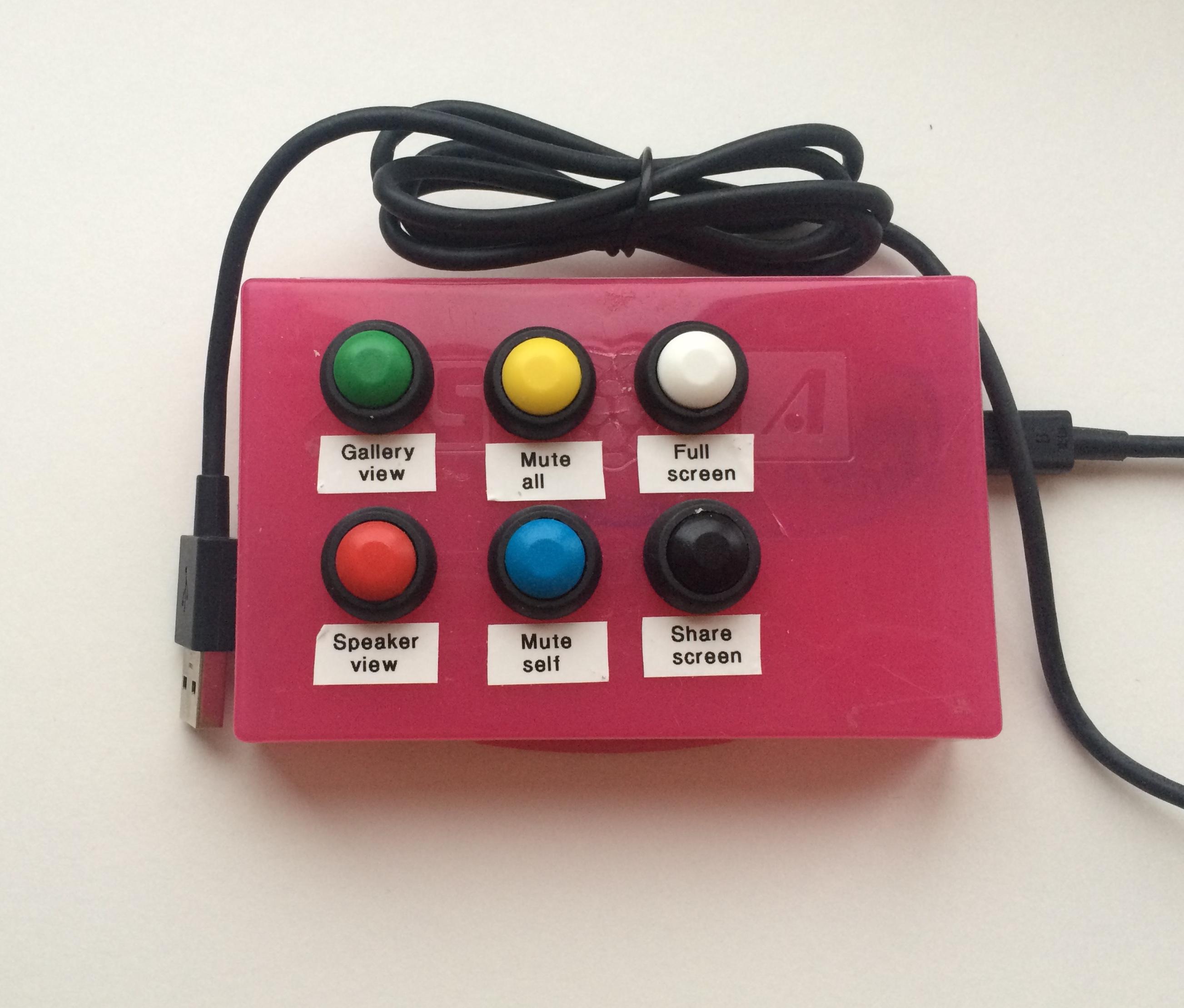
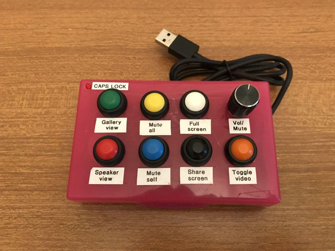
So I built this little box. It plugs into a USB port, emulates a keyboard, and generates the 6 Zoom hotkeys that I find most useful. You can easily reprogram it to generate a different set of hotkeys if you wish, or even generate hotkeys for a completey different program.
I based this project on my USB Volume Control and Caps Lock LED, in fact the code for that is included but disabled. You can enable it if you like, and add a rotary volume control and/or caps lock, scroll lock and num lock LEDs.
Supplies
The total cost could be under £10. The parts list is very simple:
- Arduino Pro Micro
- 6 push-button switches
- A box
- A microUSB cable
- A short length of rainbow ribbon cable.
You will also need:
- Soldering iron, solder, wire cutters and stripper
- Label printer
- Hot melt glue gun.
In principle you could use a different Arduino, some of which are slightly cheaper. But you'd need extra libraries for the code and possibly extra components, so it's just not worth it.
I got a set of 6 push-button switches in different colours from a Far Eastersn seller, which were ideal. An eBay search for "12mm round push button switch" or "PBS-33b" should find them. These have a nice positive action - no chance of acidental button pushes.
For the box, an ABS plastic project box would be ideal but I couldn't find one a suitable size. I considered using a cassette tape box, but then found a box that my original first generation Raspberry Pi came in.
You can use any connecting wire but rainbow ribbon cable makes it easy. I used a piece of thick copper wire for the common push button connection, only because I'd used it to support the push buttons for testing before I found a suitable box.
The Box
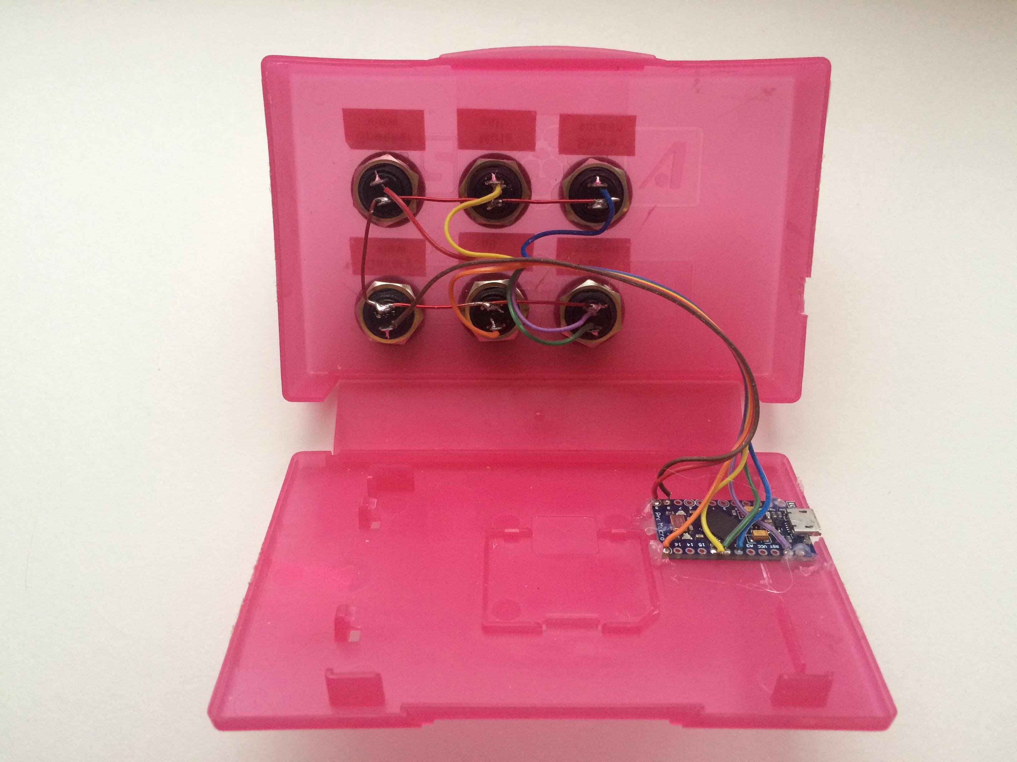
There are various possibilities for the box, and you may be able to think of more.
- An ABS project box is easy to drill for the push buttons but all the ones I could find were either too big or too small. There's one with a compartment for a 9V battery which was the nearest, but wouldn't have left much room for the button labels.
- A cassette tape box (or the box from a first generation Raspberry Pi) is about the right size, but the plastic is thin and brittle, and it's hard to drill more than a small hole without it cracking. (Mine did crack, and neither superglue nor expoxy resin bonded very well to the plastic. There's a small broken piece of plastic held in place mainly by one of the push buttons.) It might be less liable to crack if you stick sticky labels to both sides before drilling. Using a router might be more successful, or drilling a small hole and enlarging it with a dremel.
- If you have access to a 3D printer you could make a box of just the size you want, or you could laser-cut a box in thin plywood.
If you use the same buttons as I did, you'll need to make six 15mm holes. Space them sufficiently so you can stick a label under each.
Place the Arduino in the bottom of the box and offer it up to one of the sides. Make a hole for the microUSB connector to protrude through.
Wiring It Up
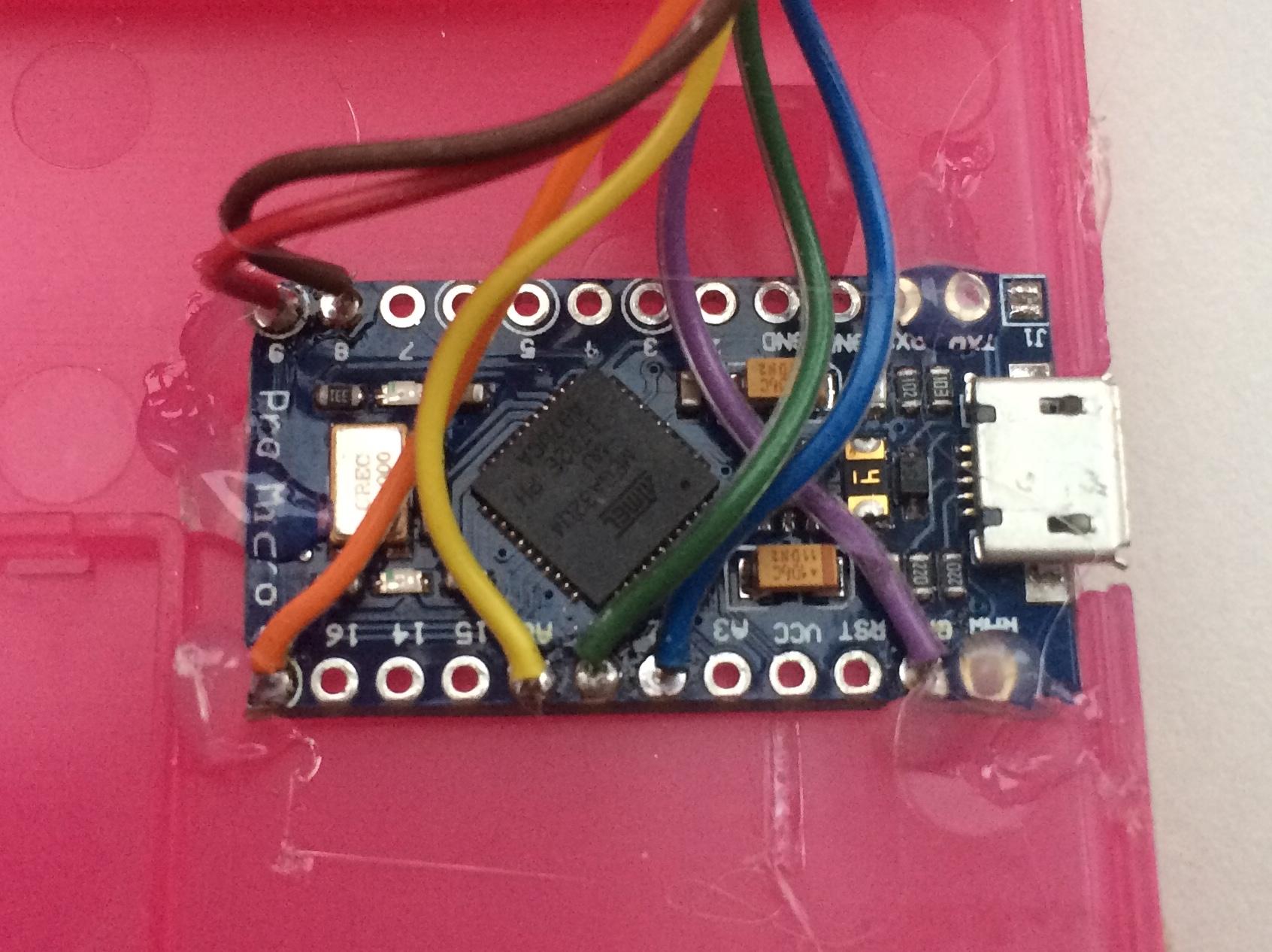
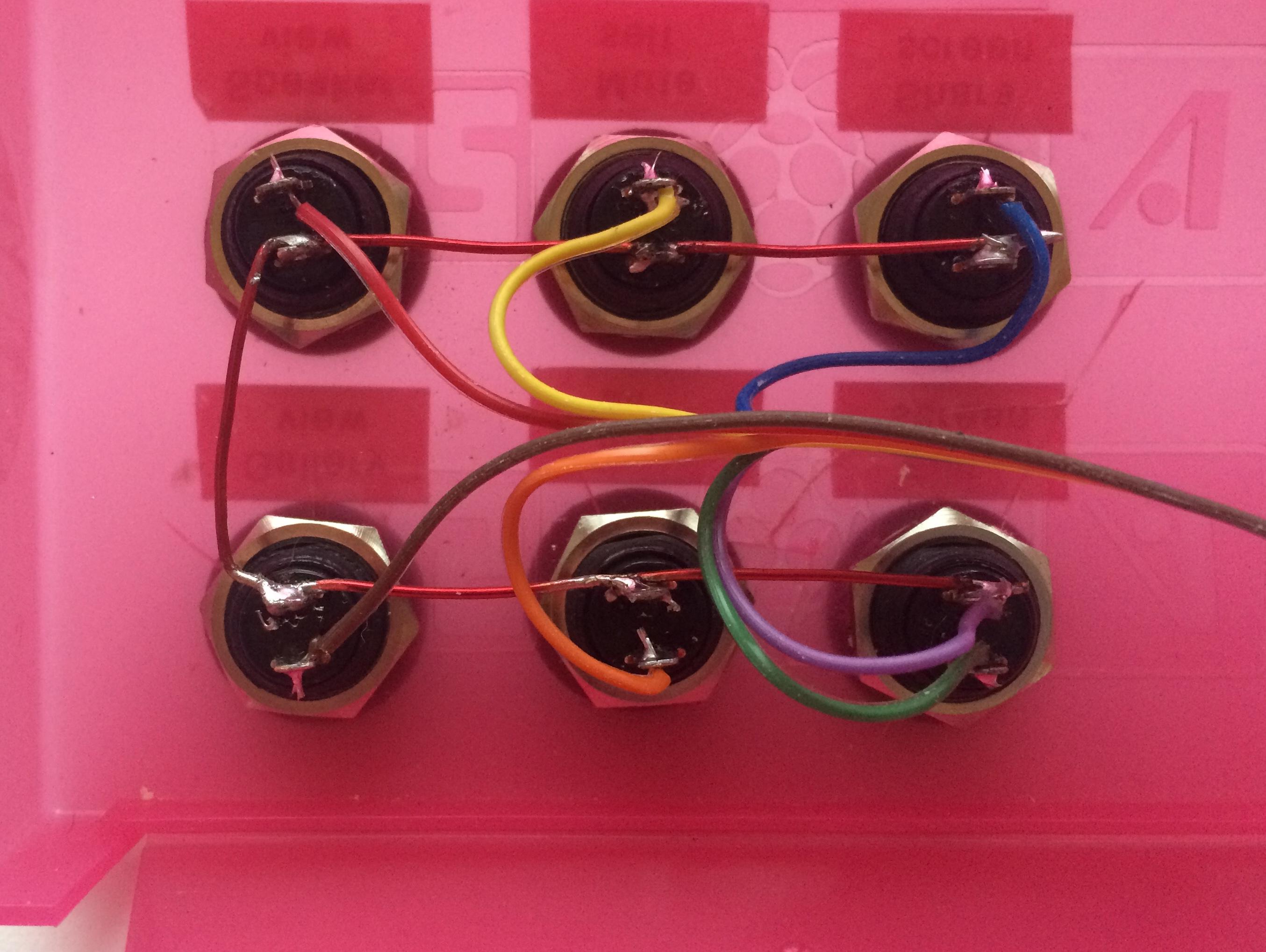
Examine the Arduino Pro Micro carefully, and identify the connections marked 8, 9, 10 and A0, A1 and A2. Use, respectively, the brown, red, orange, yellow, green and blue strands of the ribbon cable to connect these to one connector each of push buttons 1 to 6.
Wire the remaining connectors of all 6 push buttons together, and then wire them on to the Arduino connector marked GND using the violet strand.
You can now locate the Arduino in its correct position with its microUSB connector protruding through the hole you made for it. Fix it in place with a few blobs of hot melt glue.
You can label the buttons with a label printer, or if it's a laser cut box you could burn the labels with the laser.
Programming
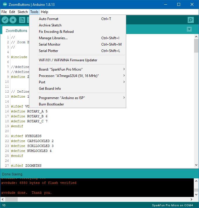
If you haven't used Arduino before you will need to download and install the Arduino IDE from the Arduino Download site.
Download the ZoomButtons.ino file, then doble-click it. The Arduino IDE will launch, and say that ZoomButtons.ino needs to be in a folder named ZoomButtons. Click OK.
From the drop-down menu items at the top of the Arduino, select Tools - Manage Libraries...
In the search box type HID-Project and press Enter. When HID-Project by NicoHood appears, click the Install button. You can now close the Library Manager.
From the drop-down menus, select Tools - Board - SparkFun AVR Boards and select SparkFun Pro Micro.
If you don't see SparkFun AVR Boards, select Boards Manager instead. This looks very much like the Libraries Manager. Search for Sparkfun AVR Boards and install it. You can now select the SparkFun Pro Micro as above.
Under the Tools menu it should now say Board: Sparkfun Pro Micro. Hover your mouse over the Processor line beneath and select ATmega32U4 (5V, 16MHz) if it's not already selected.
Just beneath Processor, select Port and note which Serial ports (if any) are listed.
Now plug in your your Zoom control box using the microUSB cable. When you select Tools - Port it should now show one more Serial port. Select this.
Having completed all that you should be ready to compile and upload the code to your Arduino. From the top menu, select Sketch - Upload (not Upload using Programmer). In the bottom pane of the Arduino IDE you will see the sketch being compiled and then "Linking everything together...", and shortly afterwards it will attempt to upload your compiled code. You should see a series of # marks as it uploads then verifies the code. If all goes well it should finally say "avrdude done. Thank you." (Very polite of it!)
Problems?
The Pro Micro normally works fine but uploading your sketch to it, itcan be a little temperamental. The one I used previously in my USB Volume Control a couple of years ago had an earlier version of the bootloader which required a reset button, but this is not necessary for current versions. Should you have problems you can try the upload instructions in that Instructable. This also gives an alternative method which doesn't depend on the bootloader.
Downloads
Using ZoomButtons With Zoom
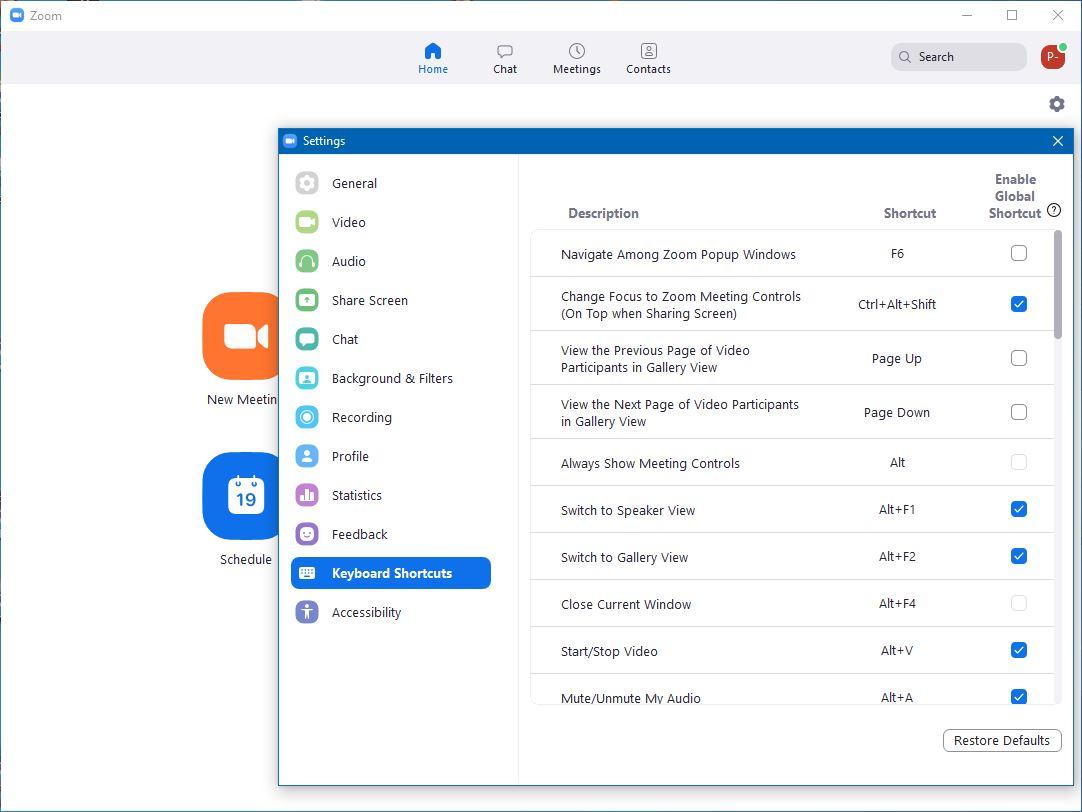
In Zoom, click on the Settings cog wheel icon in the top right and select Keyboard Shortcuts. Against each of the shortcuts that you want to use, select the Enable Global Shortcut check box. This means that the keyboard shortcut will be recognised and actioned by Zoom even if you're currently interacting with another program.
Should a shorcut key combination clash with one you use with another program you are likely to be using at the same time, you can select the key combination and change it. You will then have to change the Arduino sketch to match.
Modifications and Taking It Further
Changing key combinations
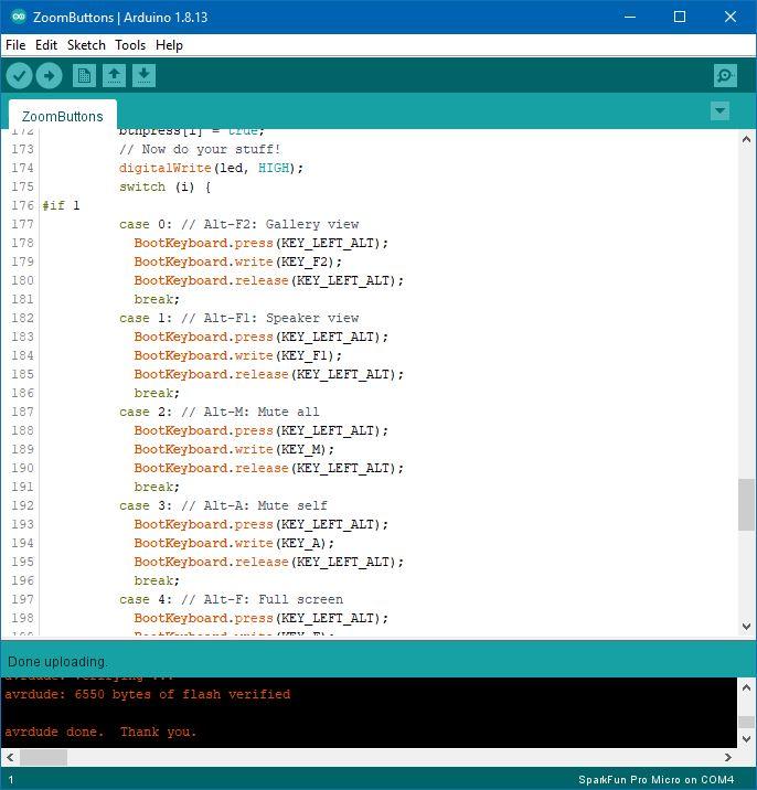
It's easy to modify the Arduino sketch to change the key combinations it generates if you want to assign buttons to different Zoom hotkeys. Scroll through the Arduino sketch until you come to the line
switch(i) {Under each of the case statements is the key combination for one of the 6 keys, numbered 0 to 5. For any of the modifier keys (Shift, Ctrl, Alt) the BootKeyboard.press and Boot.Keyboard.release functions press or release that key, respectively. For other keys, the BootKeyboard.write function presses and immediately releases the key.
For a list of the codes for other keys, open your Arduino folder with File Explorer (usually My Documents\Arduino), and navigate to libraries\HID-Project\src\KeyboardLayouts. Open ImprovedKeylayouts.h with Notepad.
If you get errors when you try to compile, double-check your spelling. Missing a semi-colon at the end of a line is a very common mistake, as is unmatched parentheses. Check you haven't lost the break; statement at the end of each case. If you do it'll simply run on and perform the next key combination as well.
If you're not sure it's working
If immediately after the switch statement you change the #if 1 to #if 0, instead of the key combinations it will then simply generate the digits 0 to 5 for the respective buttons. You will see these if you run Notepad.
You want a volume control or caps/scroll/numlock LEDs as well?
The Arduino sketch also incorporates the code for my USB Volume Control and Caps Lock LED Instructable.
Near the top of the sketch you will see 3 lines
//#define VOLUME
//#define KYBDLEDS
#define ZOOMBTNS
All you have to do is uncomment the VOLUME and/or the KYBDLEDS lines by deleting the double slash.
Refer to my other Instructable for how to wire up the extra components.
Since competing this Instructable I decided to add a 7th button, a volume control and a Caps Lock LED.