Zero to Breadboard Simulation
by Autodesk Circuits in Circuits > Electronics
189706 Views, 578 Favorites, 0 Comments
Zero to Breadboard Simulation
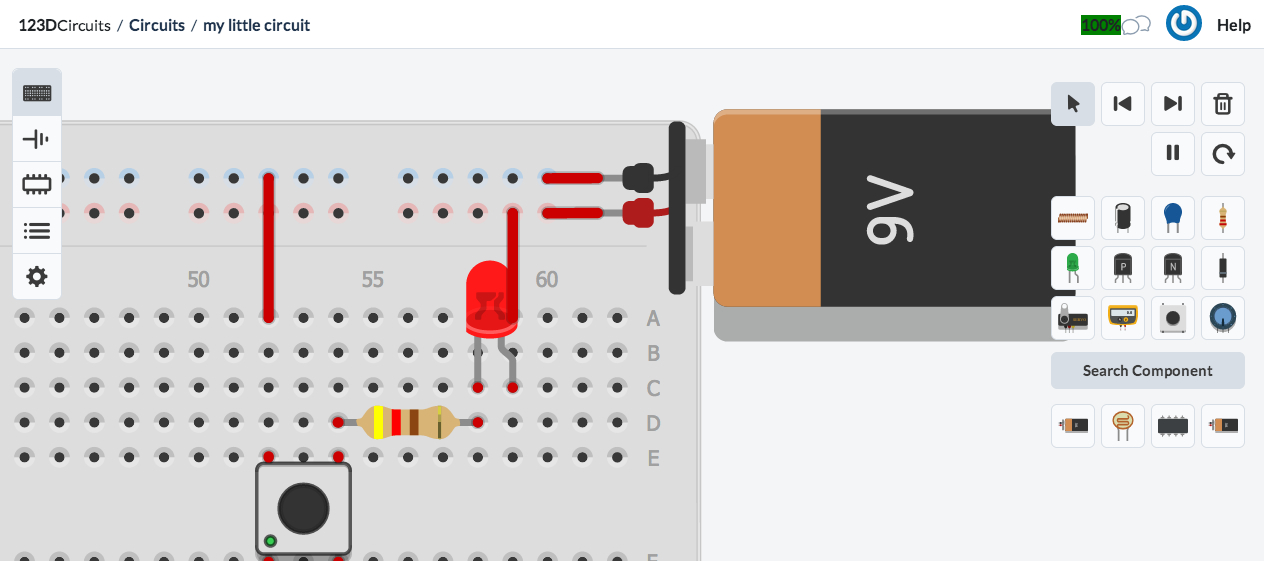
This instructable is a step by step guide to design and simulate a simple electronics project on 123D Circuits using a virtual breadboard design which is linked to schematic and layout views.
Create an Account

Go to 123d.circuits.io and fill in your user name, email and password.
Creating a Breadboard Circuit
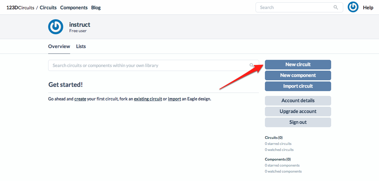
Once you are signed in, you'll see your dashboard.
From here you can:
1. Make new circuits
2. Add new components
3. Import circuits from Eagle
>> click on "New circuit"
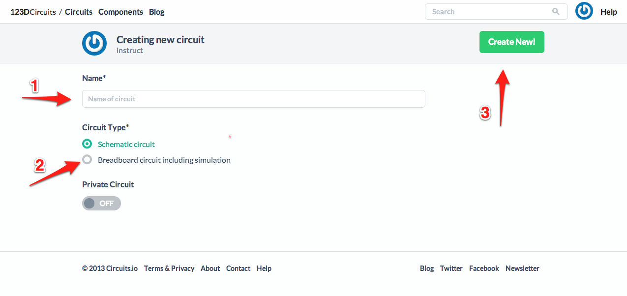
Now you have to:
1. Name your circuit
2. Choose if it's a regular schematic or one with breadboard view and simulation
3. Select Breadboard circuit
3. Click on "Create New!"
From here you can:
1. Make new circuits
2. Add new components
3. Import circuits from Eagle
>> click on "New circuit"
Now you have to:
1. Name your circuit
2. Choose if it's a regular schematic or one with breadboard view and simulation
3. Select Breadboard circuit
3. Click on "Create New!"
Editor Overview
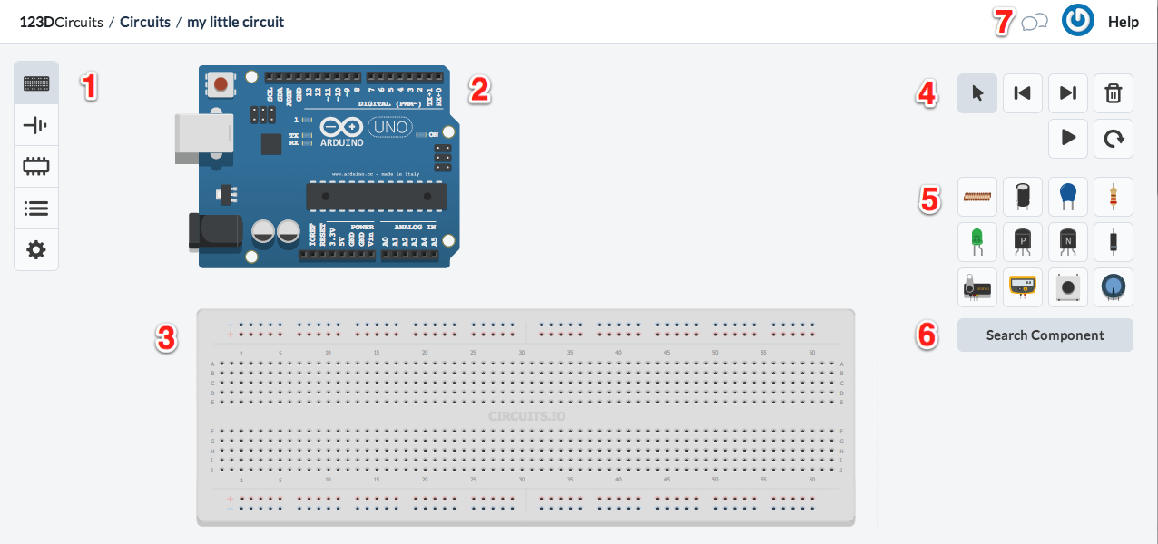
Here is an overview of the editor window:
1. The views: Breadboard, Schematic, PCB, Bill Of Materials
2. The Arduino: you can upload code, and connect components to the terminals. This can also be used as a power supply.
3. The breadboard: you can place components on this.
4. The controls.
5. Tool box: take here the basic components you need.
6. You can search for the components that aren't in the toolbox.
7. Chat box for collaborative editting.
Create Your Breadboard Design
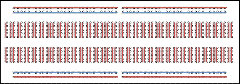
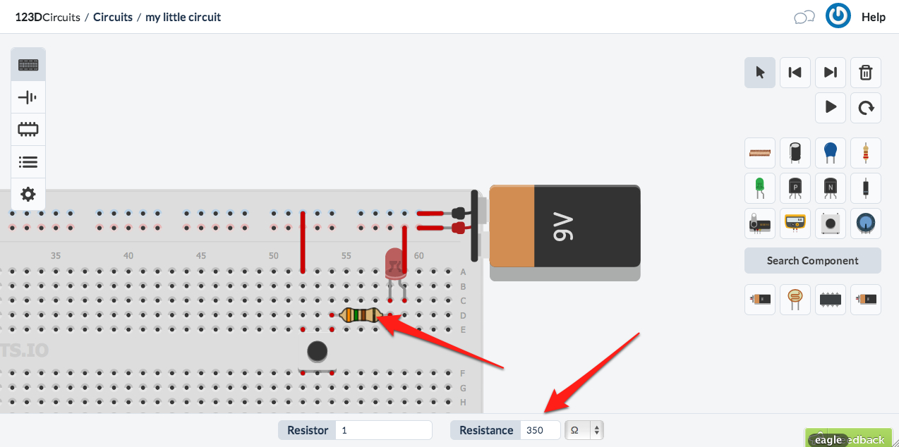
The first included image shows what the internal connections of a breadboard are.
First delete the Arduino because we don't need it in this instructable.
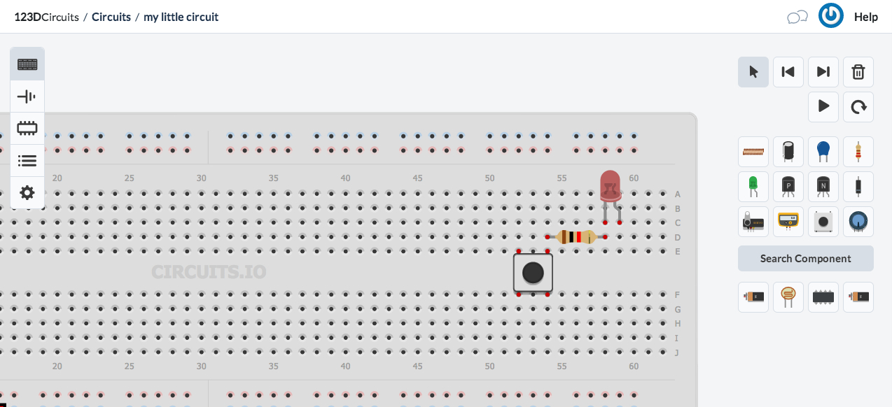
Add an LED, a resistor and a button from the tool box and place it on the breadboard.
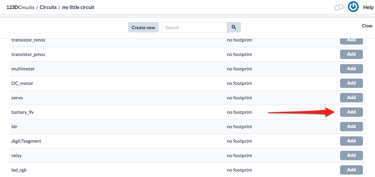
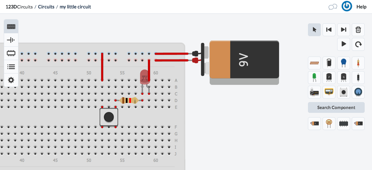
Now we want to add a power supply. Click on "Search Component", scroll down a bit and add a 9V battery. Connect everything up as can be seen in the screenshot.
We also need to set the resistor value. First we need to calculate the required resistance.
R=U/I Resistance=Voltage/Current
The maximal voltage over an LED is 1.7V, and the Voltage of the battery is 9V. So the Voltage over the resistor must be 7.3V. An LED uses 20mA = 0.02A when on.
R = 7.3V / 0.02A = 365Ohm
Click on the resistor and set it's value in the inspector you can see at the bottom of the screen.
Simulate the Circuit
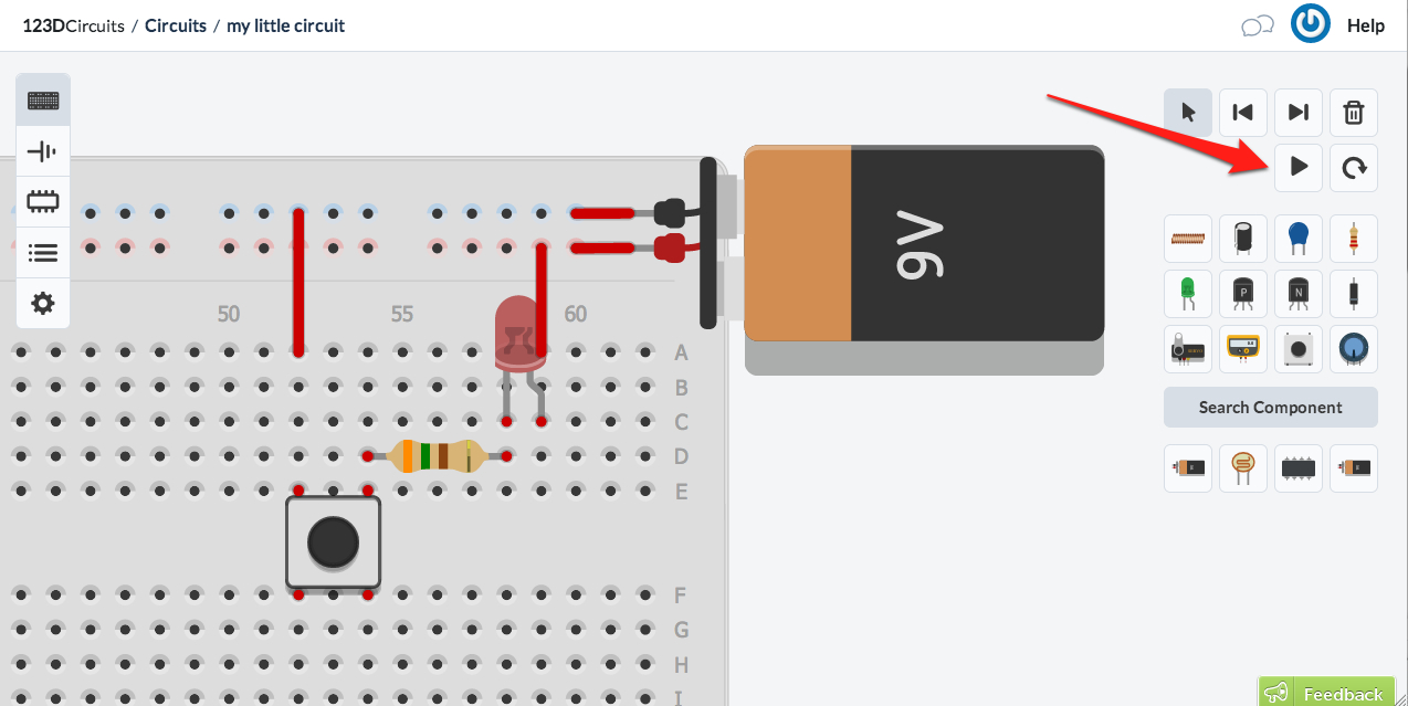

To simulate the circuit push the play button. Now press the push button and the LED will light up.
Get Insight in the Circuit Using the Multimeter
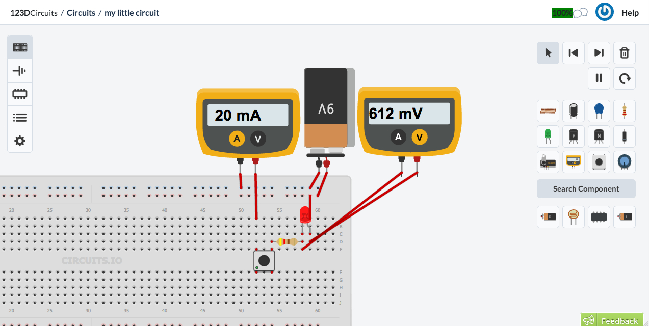
You can add multi-meters to measure voltage and current in the circuit. You see there is 20mA running through the circuit and there is 0.6V over the LED. If you make the resistance too small, you will see that the LED explodes because you are driving it with too much current.
Good that this is a simulation, one more LED saved :)
Good that this is a simulation, one more LED saved :)