Z80-MBC2 Programming the Atmega32a
by coopzone in Circuits > Microcontrollers
2446 Views, 9 Favorites, 0 Comments
Z80-MBC2 Programming the Atmega32a
Supplies
Your z80-MBC2 board nice and freshly built ready for the atmega32a
An arduino mini (or any version you have hanging around)
The software for the atmega32 from https://hackaday.io/project/159973/files
Add support for the Atmega32 chip from https://github.com/MCUdude/MightyCore
The Programmer, Arduino Mini Version
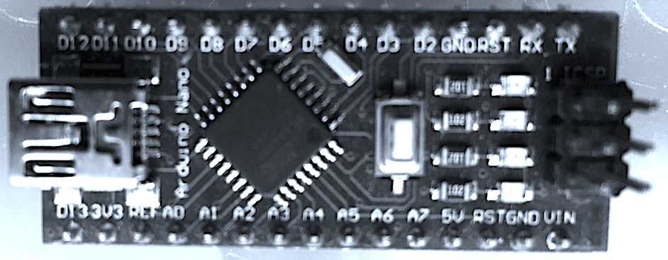
I used a dedicated Arduino mini clone. I built this into an ICSP programmer a long time ago and use it for all sorts. Mostly uploading boot loaders (as we will now)
You can create your own version either dedicated or temporary using any Arduino board (328A or above). You program your board using the Arduino-IDE. The software for the ICSP programmer is found under the file, examples menu, look for ArduinoISP. Open the example and upload the program to your board.
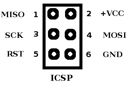
Next you need to connect the following pins to the ICSP header on the MBC2. Use 6 female-to-male or female-to-female, depending on the arduino you are using, connector leads, connected like this (also see pinout above).
For some Arduino boards the pins may vary, read the notes at the top of the sketch you just uploaded or see https://www.arduino.cc/en/Tutorial/BuiltInExample... many more pages exist to help you identify the correct pins.
Arduino	Name	ICSP
10	Reset	5
11	MOSI	4
12	MISO	1
13	SCK	3
GND	Gnd	6
+5v	Vcc	2
The Programmer, Arduino Version
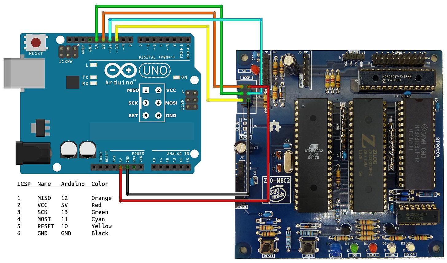
I used a dedicated Arduino mini clone as in the above Step. The version shown here was contributed and used by Guido Lehwalder all credit to him for working out the pin connections.
You can create your own version either dedicated or temporary using any Arduino board (328A or above).
Connecting to the Z80-mbc2
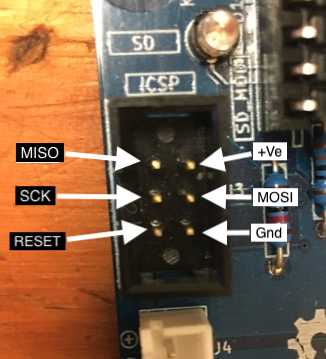
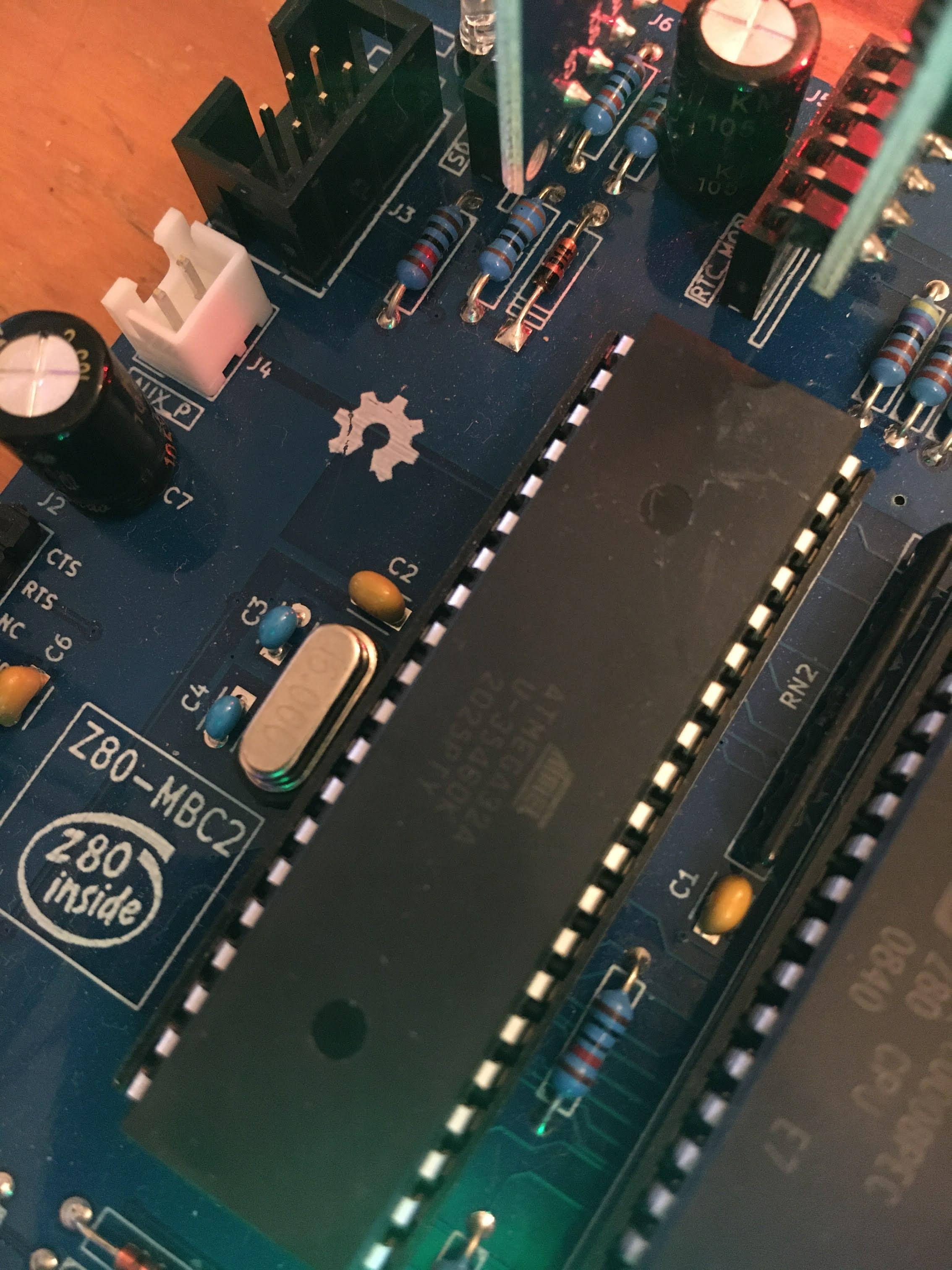
Look closely at the MBC2 board to identify pin 1(MISO) on the ICSP. Connect your wires from the programmed Arduino Mini to each pin on the MBC2 header.
IMPORTANT: Before powering the board up remove the SD-CARD and REAL TIME CLOCK modules. Also unplug any USB serial connections you may have. The only connections to the MBC2 are to the ICSP header.
Add Support for the Atmega32 Chip
It's now time to download the support pack for the atmega32, you can use the board manager as described on the developers github site https://github.com/MCUdude/MightyCore#boards-manager-installation
Like this:
- Open the Arduino IDE
- Open the File > Preferences menu item.Enter the following URL in Additional Boards Manager
- URLs:https://mcudude.github.io/MightyCore/package_MCUdude_MightyCore_index.json
- Open the Tools > Board > Boards Manager... menu item.
- Wait for the platform indexes to finish downloading.
- Scroll down or use the search option to find MightyCore until you see the MightyCore entry and click on it.
- Click Install.
- After installation is complete close the Boards Manager window.
Burn the Boot Loader
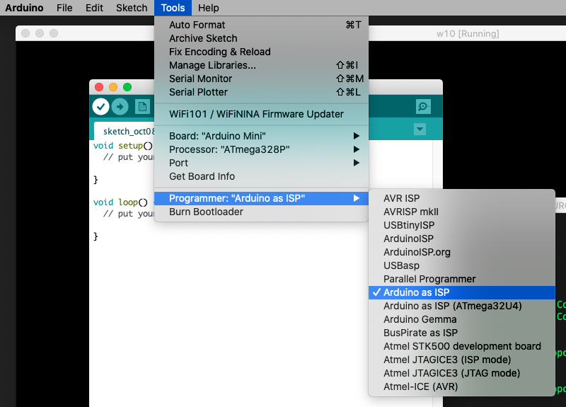
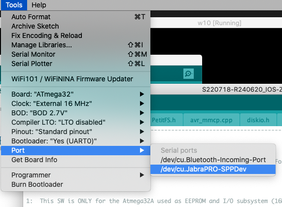
Before you select the Atmega32, make sure you have selected the programmer to use,
Tools menu, Programmer, choose arduino as ISP.
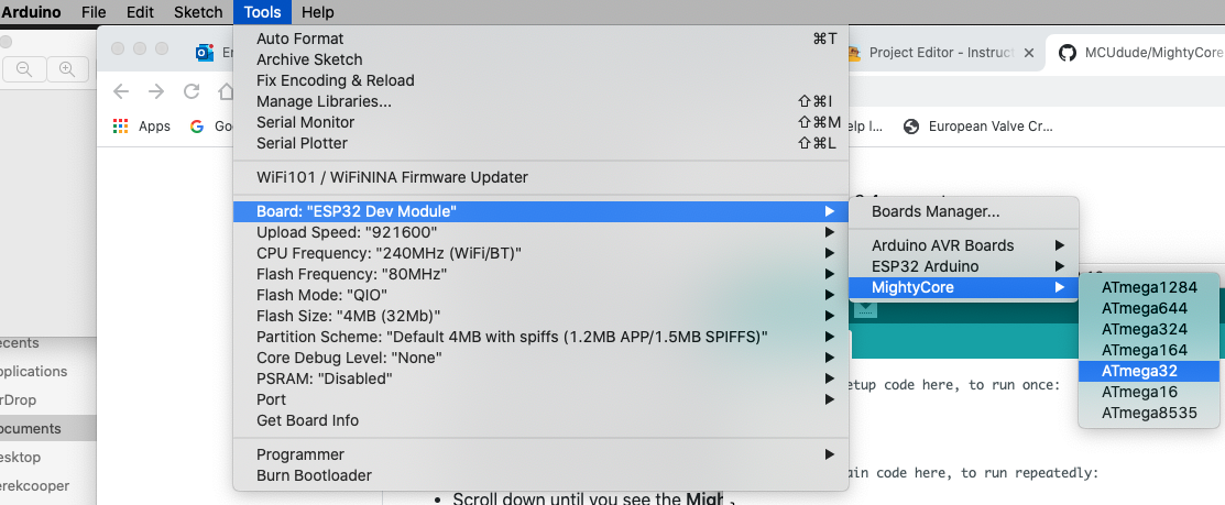
You can now use the Arduino-IDE to choose the Atmega32 chip ready to upload the bootloader.
From the Tools menu, choose Board, MightyCore, then Atmega32
Now you should be able to upload the bootloader,
Choose Tools, Burn Bootloader.
When it's finished the green LED should be doing a double flash, this indicates the bootloader is waiting to be told what to boot. You may need to press reset to get this.
Your ready to upload the actual sketch used in the MBC2 board, now the bootloader is installed you can upload the MBC2 software directly to it, now you have a bootloader you can also upload any future upgrades using the steps below.
Power off (unplug the programmer) re-connect your USB serial cable. You don't need to use the ISP programmer to complete the upload from now on.
Program the MBC2 Software
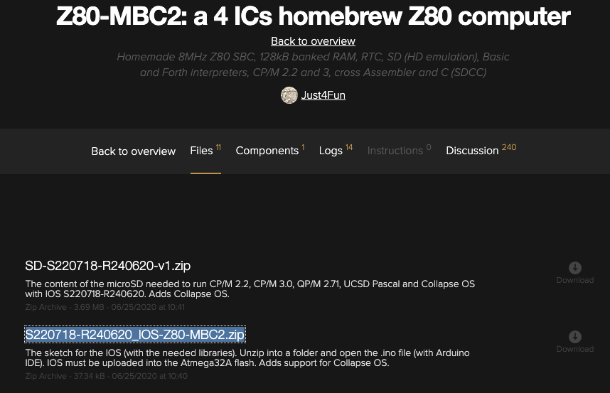
Get the latest version of the software from https://hackaday.io/project/159973/files
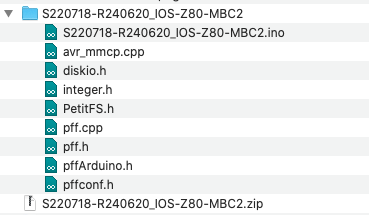
It will be named something like, S220718-R240620_IOS-Z80-MBC2.zip. There are two versions, this one and one called 'lite' the lite one does not support booting from the SD-Card.
When you unzip it make sure it's all in a folder by the same name as the zip file, this is the default for most unzipping utilities.
Open the ino file in the Arduino IDE
Make sure you have the correct board chosen in the Tools, Board menu. Atmega32. Also check that the USB port is selected and the correct defaults like the picture above.
You can now click -> (compile and upload) to program the Atmega32a.
All done
Trouble Shooting and Comments
So far,
I have used 3 different variants and managed to get this technique to work will all of them, but some required extra work:
Mini Clone:
Works as is or at least mine does!
Micro clone:
Not sure this is an official board. it's basically a mini but without the onboard USB adapter. This seems to have the reset issue, you can leave the DTR cable from the USB/TTL adapter disconnected, thus preventing the reset.
arduino duemilanove:
Again this board has the reset issue, and as many other have already said, you need to add a 10-25uf capacitor between the reset pin on the board and ground.
Power issue:
Some clones don't seem to provide enough current on the 5v supply to power the Z80-mbc2 and themselves resulting in random errors. It the main tutorial it's suggested you don't connect the usb/ttl device during programming (the main ttl connector not the one on the programmer). But to help with power you can connect this, but just the +5v and 0v pins, then plug both usb plugs into the host computer. This may help with random errors.