Yuki’s Little Printer

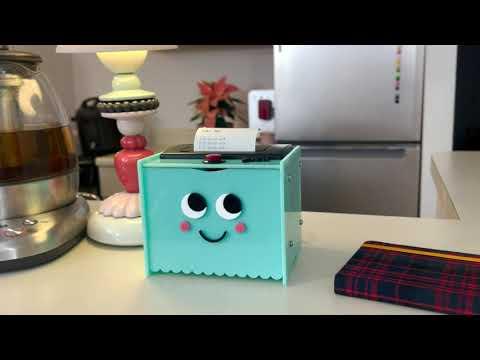
I find myself at discord between planning digitally vs analog. I like the the ease of thinking about my plan for the day through a digital template. At the same time, I find it a little distraction to refer to my plan digitally. My brain starts to check the other thousands of exciting screens pop ups on my phone. I like the non distracting nature and the touch of analog plans on paper. I like to strike things off that list. This made me think of a my own ‘Little Printer’. Little Printer is a small smart printer, connected to my devices through the internet. It prints me out my to-do and plan for the day every morning at 7am.
Supplies
Main Parts
The following are the essential parts of the 'Little Printer'
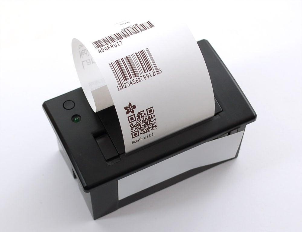
- Mini Thermal Receipt Printer
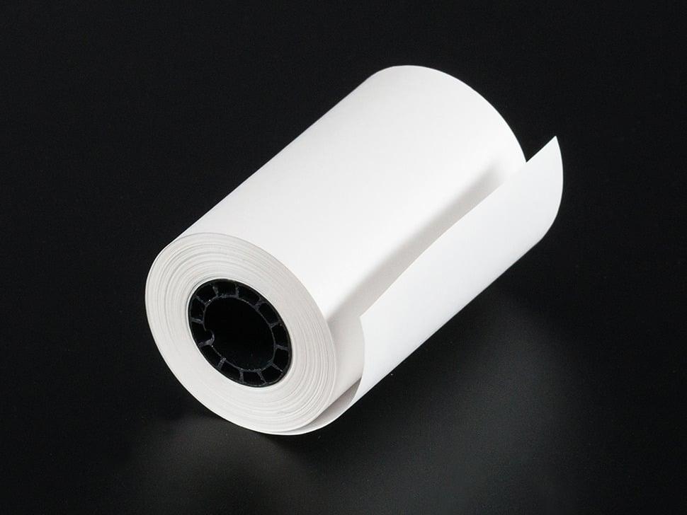
- 50' roll of thermal paper
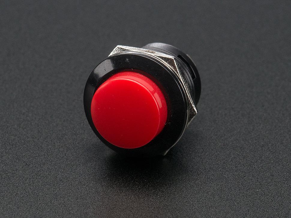
- 16mm Panel Mount Momentary Pushbutton - Red
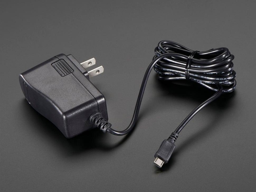
- 5V 2.5A Switching Power Supply with 20AWG MicroUSB Cable
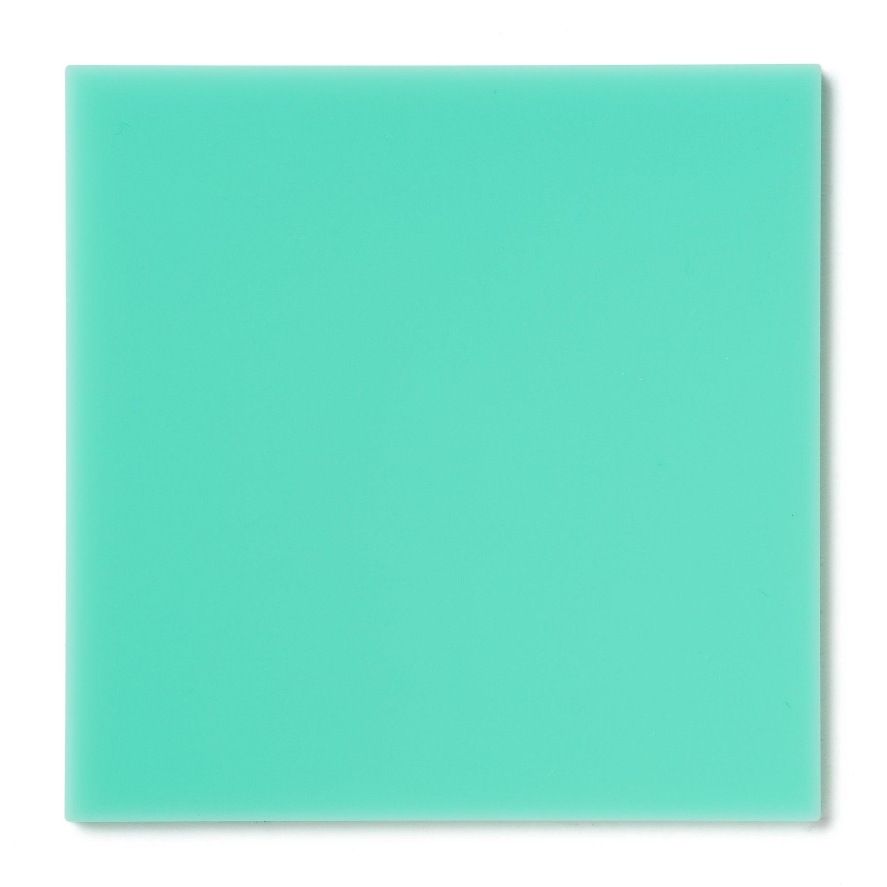
- Turquoise acrylic sheet
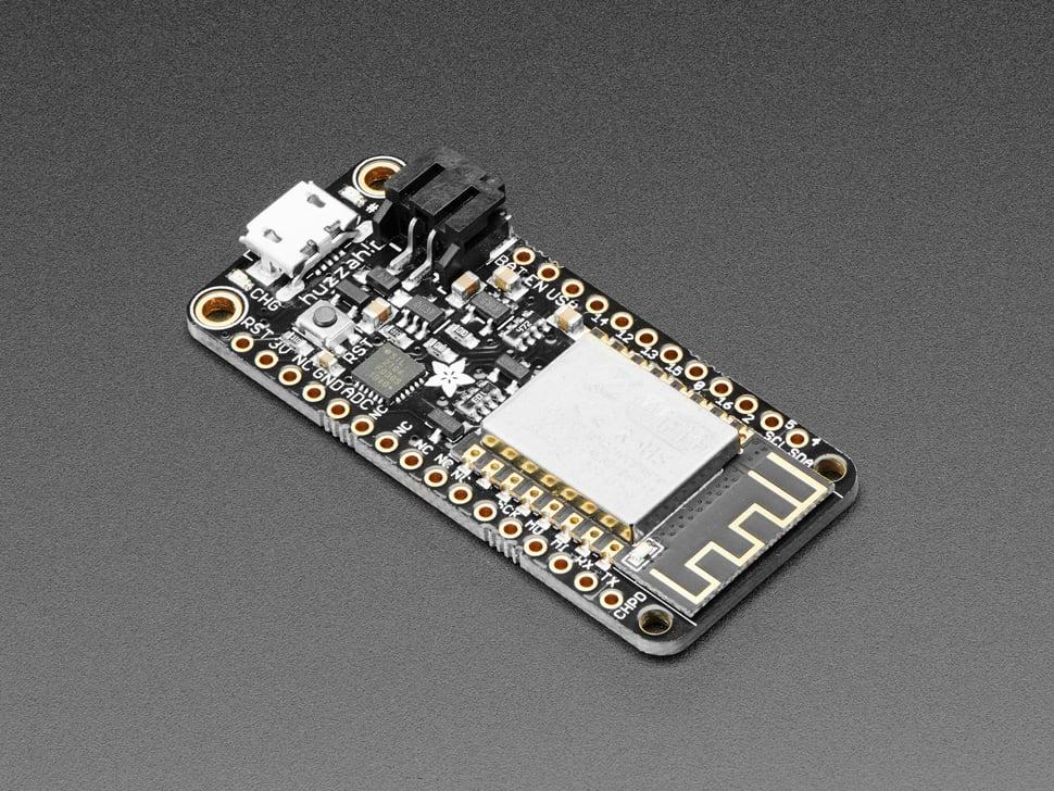
- Adafruit Feather HUZZAH ESP8266
- Ten (10) 1/2" #4-40 machine screws
- Ten (10) #4-40 nuts
- Two (2) 1/4" spacers
Assembling Tools
The following tools and items are needed for assembly and setup:
Circuit Diagram

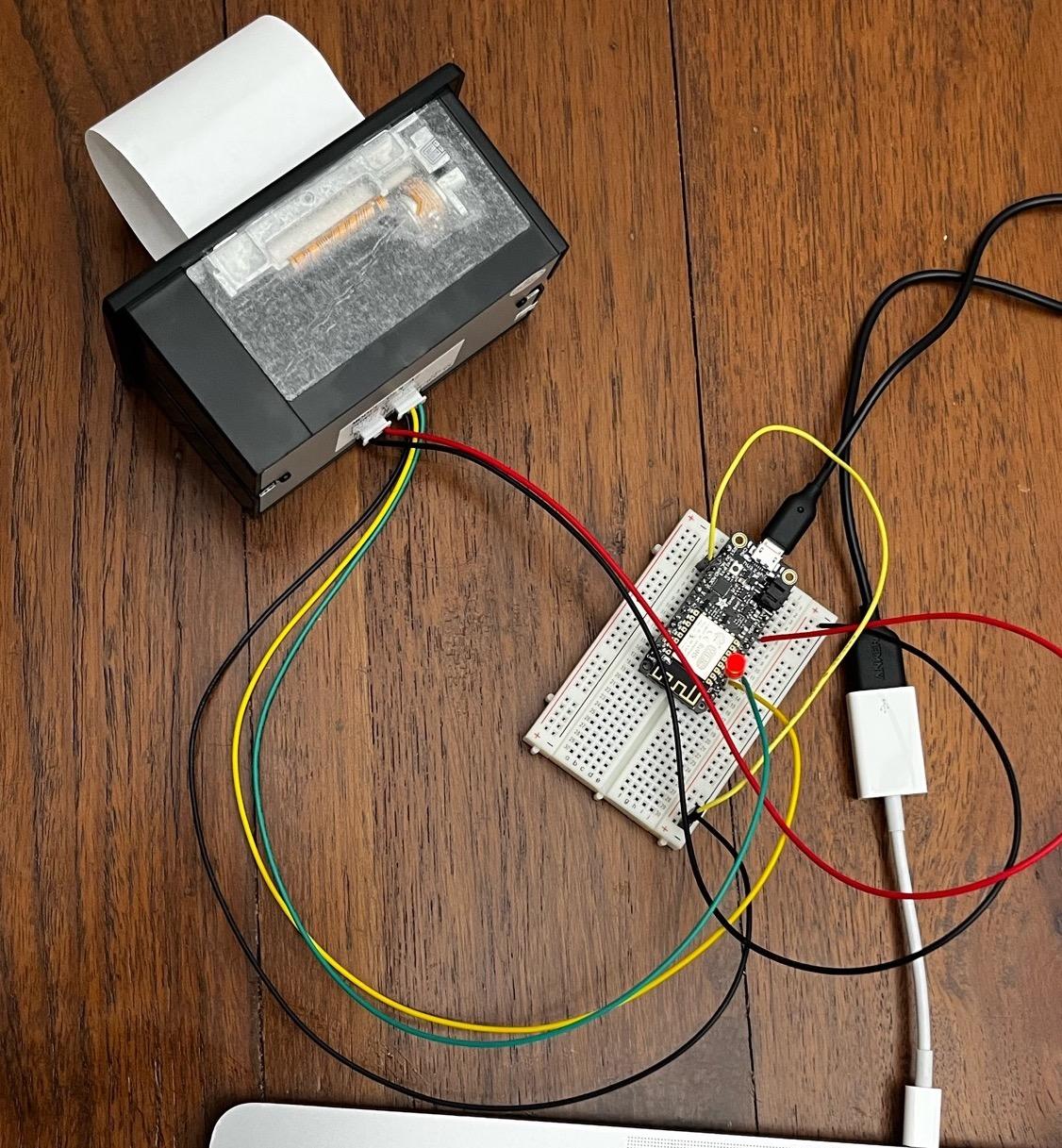
- The Huzzah board is connected to power using the 5V 2.5A with USB power supply.
- The Mini Printer is powered from the Huzzah board USB pin (Red at USB, Black at GND)
- The Mini Printer data input/outputs are connected to digital pins 0 and 16 (Green at 0 pin, Yellow at 16 pin, Black at GND)
IoT Hub Setup
With the circuit described in Step 1, we have the Mini Printer and Huzzah board with WiFi setup. Now we need a way to trigger the print calendar data action on our device from the internet. There many different IoT hub solutions available to do this. To find a suitable solution, I had 3 requirements:
- A supported Arduino SDK with samples/examples
- A cloud-to-device message API to deliver calendar data payload to the device
- A free or relatively inexpensive pricing tier
Adafruit IO
I first tried using Adafruit IO for this project. It met all the above requirements. I set up a new feed called calendar that would store my daily agenda data. I added code to my Huzzah board to listen to messages streaming into the calendar feed. (see Adafruit IO Sample Code). To test it out, I first printed the message received from the calendar feed to the Serial Monitor on Arduino IDE.
void handleMessage(AdafruitIO_Data *data) {
  Serial.println("new data received...");
  String str_data = data->toString();
  Serial.println(str_data);
}
The code worked well for small text. However, the I noticed the text getting stripped off around 53 characters. Moreover, when I tried sending text of length greater than 97 characters, the code itself would crash and restart. Trying to troubleshoot, I found that this was an existing issue with the Adafruit Arduino SDK on GitHub. Since a daily agenda would most likely be greater than 97 characters, I decided to look for another IoT solution.
Azure IoT Hub
The Azure IoT Hub also meets the above requirements. The Free tier has a limit of 8,000 message/day limit, but we would not need more than 1-2 a day when in operation, and not more than 100-200 while testing. The following are the steps to set up the Azure IoT hub.
A. Create IoT hub
- Create a new Azure subscription at portal.azure.com
- On the Azure homepage, select the + Create a resource button.
- From the Categories menu, select Internet of Things then IoT Hub.
- On the Basics tab, complete the fields as follows:
- Subscription: Select the subscription created in step 1.
- IoT hub name: Enter a name for your hub. I named my IoT hub calendar.
- Region: Select the region, closest to you. I used East US.
- Select Next: Networking:
- Set Connectivity configuration to Public access
- Select Next: Management
- Set Pricing tier to Free
- Select Next: Review + create and click Create to create the IoT hub
B. Register your device
The Huzzah board cannot connect to the IoT hub unless it has an entry in the identity registry. The following are the steps to register the Huzzah board for the IoT hub
- In the Azure IoT hub navigation menu, open Devices, then select Add Device to add a device in your IoT hub.
- In Create a device, provide a name for the new device, such as huzzah, and select Save. This action creates a device identity for the IoT hub.
- After the device is created, open the device from the list in the Devices pane. Copy the Primary Key. This key is used by device code to communicate with the hub.
To connect with the IoT hub, we need 3 things -
- IoT hub hostname. It is the hub name chosen in step A.4b followed by .azure-devices.net (calendar.azure-devices.net for me). You can also look it up under hostname on the IoT hub Overview tab.
- Device name. The device name chosen in step B.2 (huzzah for me)
- Device Primary Key. Copied in step B.3
Now we are ready to connect our Huzzah board to the Azure IoT hub.
Code
Code
The code I used is a modified version of Azure IoT Hub SDK example for ESP8266. The Azure SDK example provides a template for connecting the Huzzah board to WiFi and set up telemetry with Azure IoT Hub. I modified the code to include functions to listen to messages from Azure IoT hub and initiate print commands to the Mini Printer.
Configuration
The configuration values are in a separate header file iot_configs.h. Please modify this file according to your WiFi information and your Azure IoT hub information from Step 2.
// Wifi
#define IOT_CONFIG_WIFI_SSID "Enter Wifi Name here..."
#define IOT_CONFIG_WIFI_PASSWORD "Enter Wifi Password here..."

// Azure IoT
#define IOT_CONFIG_IOTHUB_FQDN "Enter Azure IoT hub hostname here..."
#define IOT_CONFIG_DEVICE_ID "Enter Azure IoT hub Device name here..."
#define IOT_CONFIG_DEVICE_KEY "Enter Azure IoT hub Device Primary Key here..."
Azure IoT Hub Code
The primary function here is establishConnection. This function connects to WiFi, initializes time, sets up the cloud-to-device callbacks and establishes connection with the Azure IoT Hub.
static void establishConnection() {
  connectToWiFi();
  initializeTime();
  printCurrentTime();
  initializeClients();
  connectToAzureIoTHub();
}
In the initializeClients function, we register function receivedCallback as the function to be triggered when we send messages from the Azure IoT hub to the device. The cloud message is received as a byte array of size length. We cast each byte as a char and concatenate this message to our agenda string. We then pass this string to our printAgenda function that triggers the print action on our Mini Thermal Printer.
void receivedCallback(char* topic, byte* payload, unsigned int length) {
  Serial.print("Received [");
  Serial.print(topic);
  Serial.print("]: ");
  String agenda = "";
  for (int i = 0; i < length; i++) {
    char x = (char)payload[i];
    Serial.print(x);
    agenda.concat(x);
  }
  Serial.println("");
  printAgenda(agenda, length);
}
Printer Code
To configure our printer, as described in our circuit in Step 1, we set up the transmit and receive pins at digital pins 16 and 0 respectively. We also define initPrinter and resetPrinter functions to initialize and reset.
#include "Adafruit_Thermal.h"
#include "SoftwareSerial.h"

#define TX_PIN 16  // Arduino transmit  YELLOW WIRE  labeled RX on printer
#define RX_PIN 0   // Arduino receive   GREEN WIRE   labeled TX on printer

SoftwareSerial mySerial(RX_PIN, TX_PIN);  // Declare SoftwareSerial obj first
Adafruit_Thermal printer(&mySerial);      // Pass addr to printer constructor

// Printer functions
void initPrinter() {
  mySerial.begin(19200);  // Initialize SoftwareSerial
  printer.begin();
}

void resetPrinter() {
  printer.feed(5);
  printer.sleep();  // Tell printer to sleep
  delay(3000L);     // Sleep for 3 seconds
  printer.wake();   // MUST wake() before printing again, even if reset
  printer.setDefault();
}
For the actual print action, we define the printAgenda function and a few helper functions. We print the words "Yuki Day" at the start with Style 1 (Large, Bold with Font 'B') followed by all the lines of the agenda in Style 2 (Small with Font 'A'). After a few trials, I noticed the printer font styling would return to default after printing each line. So, I modified the code to set the styling before printing each line.
void printAgenda(String description, int length) {
  initPrinter();
  printStyle1("..............");
  printStyle1("Yuki Day");
  printer.println("");
  printLines(description, length);
  printStyle1("..............");
  resetPrinter();
}

void printLines(String str, int length) {
  String line = "";
  for (int i = 0; i < length; i++) {
    char x = (char)str[i];
    if (x == '\n') {
      printStyle2(line);
      line = "";
    } else {
      line.concat(x);
    }
  }
  printStyle2(line);
}

// Prints large and bold with Font B
void printStyle1(String str) {
  printer.setSize('L');
  printer.boldOn();
  printer.setFont('B');
  printer.println(str);
}

// Prints small with Font A
void printStyle2(String str) {
  printer.setSize('S');
  printer.boldOn();
  printer.setFont('A');
  printer.println(str);
}
Arduino setup & loop
To bring it all together, we call the establishConnection function from the Arduino setup function. In the loop function, we have code to re-establish connection if the device gets disconnected. We also call the MQTT loop function to keep the IoT hub connected.
void setup() {
  establishConnection();
}

void loop() {
  if (millis() > next_telemetry_send_time_ms) {
    // Check if connected, reconnect if needed.
    if (!mqtt_client.connected()) {
      establishConnection();
    }
    next_telemetry_send_time_ms = millis() + TELEMETRY_FREQUENCY_MILLISECS;
  }

  // MQTT loop must be called to process Device-to-Cloud and Cloud-to-Device.
  mqtt_client.loop();
  delay(500);
}
That's it. Our code is now ready to use!
Circuit Construction
I first tested the circuit on a breadboard. The thermal printer does not work well with the power from the laptop, so I used the laptop to just upload the code. After uploading the code, I switched the power to the Huzzah board from the laptop to a power socket. The blue light on the board indicates when the board is successfully connected to the internet.
Once the code was uploaded, I tested the internet message was successfully received and printed.
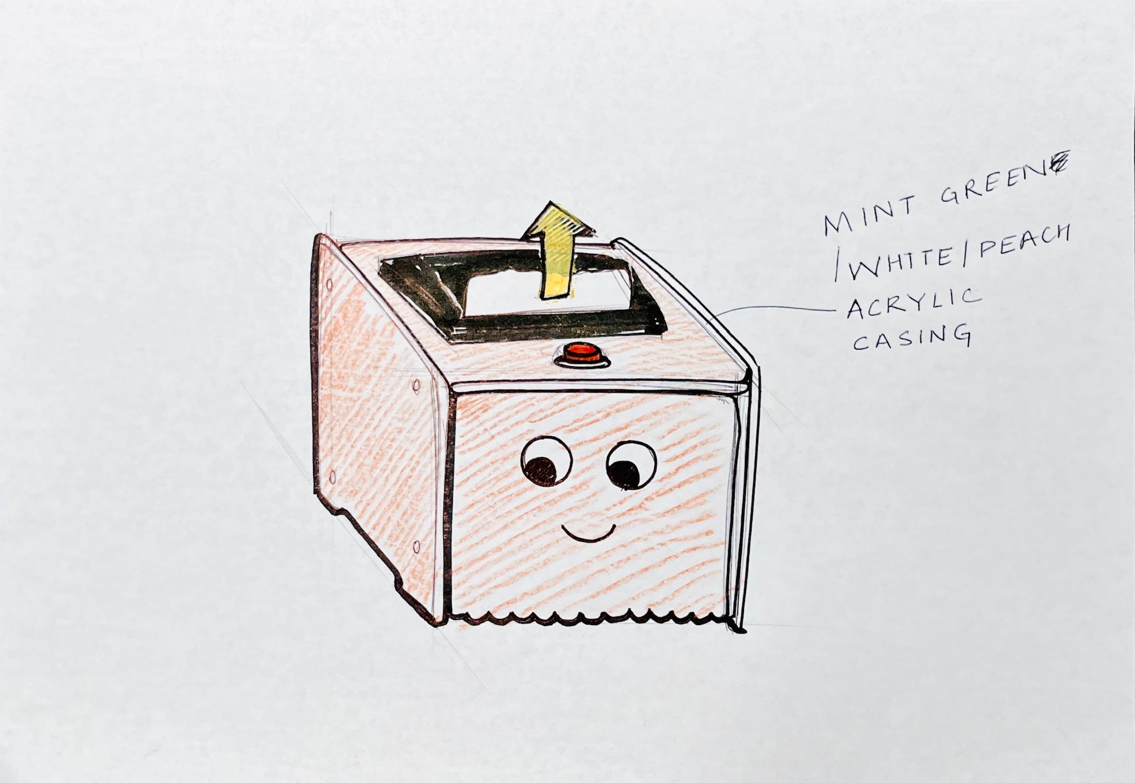
Form & Material
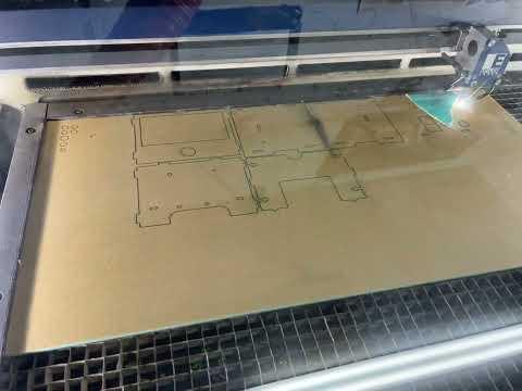
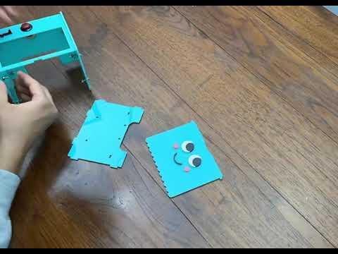
For the box enclosure, I used the Adafruit IoT printer as an example. I found the AI file from Phillip Burgess's project on Adafruit. I got a turquoise colored Acryclic sheet for my enclosure. I laser cut the sheet and assembled using screws.
Downloads
Enclosure Assembly
Celebrate and Call to Action!
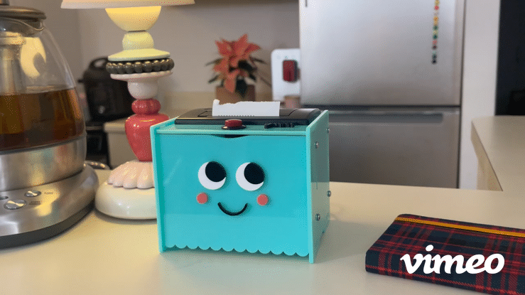
Ta Da!