Your Smart Medication Remainder
by niroshanyi in Circuits > Arduino
630 Views, 5 Favorites, 0 Comments
Your Smart Medication Remainder

Time flies, especially when managing medications. Forgetfulness can be detrimental to health, but worry no more!
Introducing MediBox, a smart medication reminder system that blends cutting-edge technology with user-friendly design, ensuring you never miss a dose again.
More Than Just a Reminder
MediBox is a comprehensive pharmaceutical storage system that goes beyond basic reminders. It combines an ESP32 microcontroller with an array of sensors and actuators to create a truly intelligent system.
Here's How MediBox Makes Time Work For You
Precision Timekeeping
MediBox utilizes an NTP client to synchronize with an atomic clock, guaranteeing accurate timekeeping no matter your location. You can even set custom time zones for personalized precision.
Customizable Alarms
Set up to three personalized medication alarms, each with its own unique time. When an alarm triggers, MediBox springs into action, sounding a clear and audible alert using a built-in buzzer.
Interactive User Interface
Navigate effortlessly through MediBox's functions using a OLED display and push buttons. Setting alarms, checking the time, and adjusting settings is a breeze, making managing your medications straightforward and intuitive.
Beyond Reminders -> Environmental Monitoring
MediBox doesn't stop at timekeeping. Integrated LDRs (Light Dependent Resistors) monitor ambient light intensity. This data is used to adjust a shaded sliding window, controlled by a servo motor, to protect medications from harmful light exposure.
Data Visualization and Control
MediBox communicates wirelessly with a Node-RED dashboard via MQTT, allowing you to view real-time and historical data on temperature, humidity, and light intensity. Remotely control the sliding window, fine-tuning the environment for optimal medication storage.
Advanced Features
MediBox stands out with its range of advanced functionalities, setting it apart from typical medication reminders
Persistent Alarms and Settings
All user configurations and alarm settings are stored in non-volatile memory, ensuring your data is safe even during power outages.
Power Management
Advanced power management strategies reduce overall power consumption, making MediBox an energy-efficient solution.
On-Change Detection
Sensors are designed to activate only upon detecting changes, further conserving energy while maintaining constant monitoring of the storage environment.
Comprehensive Monitoring
MediBox continuously tracks temperature, humidity, and light intensity, ensuring that medications are stored in optimal conditions and alerting users when parameters exceed predefined thresholds.
Supplies


Hardware Components
For the medibox project you will need following hardware components
ESP32 Development Board
This board serves as the main controller for the system, providing the necessary processing power and connectivity options.
OLED Display
The OLED display is used to provide visual feedback to the user, showing information such as the current time, alarm notifications, and system status.
Buzzer
The buzzer is responsible for generating audible alarms when medication reminders are triggered, ensuring that users are alerted to take their medication.
Push Buttons
The push buttons allow users to interact with the system, enabling them to navigate through menus, set alarms, and acknowledge notifications.
Light Dependent Resistors (LDRs)
LDRs are used to monitor the ambient light intensity. This information is used to adjust the position of the shaded sliding window, ensuring that medications are stored in optimal conditions.
Servo Motor
The servo motor controls the movement of the shaded sliding window based on the input from the LDRs and user-defined parameters.
Resisters
The resisters which are connected to the push buttons will handle the bouncing effect of the push button.So you may need 4 1K resisters
Software Components
To setup the medibox you need to install following software components.
VS Code is for editing and uploading your code snippet to esp32.Also you need to setup platformIo plugin to connect your esp32 to your computer.Here is a article how to setup VS Code and PlatformIo in instructables
Node Red
Also you need to setup the node-red to control your medibox from your computer.Here is the official guideline to setup node-red in your computer
Hardware Components
Here is the detailed document for hardware components
ESP32

Description
The ESP32 development board serves as the central processing unit of the MediBox system, responsible for executing the embedded software, controlling peripheral devices, and managing communication with the MQTT broker.
Features
- Integrated Wi-Fi and Bluetooth connectivity
- Dual-core processor for efficient multitasking
- Multiple GPIO pins for interfacing with sensors and actuators
- Low power consumption
- Support for various communication protocols
Technical Specifications
- Chipset: ESP32
- Dimensions: 58.4mm x 25.4mm
- Weight: 5g
- Power Requirements: 5V DC
- Clock Speed: Up to 240MHz
- Interfaces: UART, SPI, I2C, GPIO
- Port Mapping: Refer to the ESP32 pinout diagram for specific port mappings based on the development board model.
- Compatibility: Compatible with PlatformIO and other embedded software development platforms.
- Environmental Requirements: Operating Temperature: 0°C to 55°C, Operating Humidity: 5% to 95% RH (non-condensing)
- Installation Instructions:
- Connect the ESP32 development board to a computer via USB.
- Install the necessary drivers and development tools.
- Upload the MediBox embedded software to the ESP32 board.
- Maintenance and Support: No specific maintenance is required.
- Troubleshooting: Verify proper power supply and connections. Consult the ESP32 documentation for support and troubleshooting.
- References: Espressif Systems
SSD1306

Description
The OLED display provides a visual interface for the MediBox system, displaying the current time, date, sensor readings, alarm status, and user menus.
Features
- High contrast and wide viewing angle
- Low power consumption
- Compact size
- I2C communication interface
Technical Specifications
- Display Size: 128x64 pixels
- Dimensions: 27mm x 27mm
- Weight: 2g
- Power Requirements: 3.3V DC
- Interfaces: I2C
- Port Mapping:
- SDA: GPIO 21
- SCL: GPIO 22
- Compatibility: Compatible with Adafruit SSD1306 library and other compatible libraries.
- Environmental Requirements: Operating Temperature: -40°C to 85°C
- Installation Instructions:
- Connect the OLED display to the ESP32 development board using I2C communication lines.
- Install the Adafruit SSD1306 library.
- Configure the library for the OLED display's I2C address.
- Maintenance and Support: No specific maintenance is required.
- Troubleshooting: Verify proper power supply and connections.
- References: Adafruit
DHT22

The DHT22 sensor provides accurate and reliable temperature and humidity readings for the MediBox system, ensuring optimal environmental conditions for stored medications.
Features
- High accuracy and stability
- Low power consumption
- Wide measurement range
- Simple communication protocol
Technical Specifications
- Temperature Range: -40°C to 80°C
- Humidity Range: 0% to 100% RH
- Accuracy: ±0.5°C (temperature), ±2-5% RH (humidity)
- Dimensions: 15.1mm x 25mm x 7.7mm
- Weight: 2.4g
- Power Requirements: 3.3V to 5.5V DC
- Interfaces: Single-wire digital
- Port Mapping:
- Data: GPIO 26
- Compatibility: Compatible with Adafruit DHT library and other compatible libraries.
- Environmental Requirements: Operating Temperature: -40°C to 80°C
- Installation Instructions:
- Connect the DHT22 sensor to the ESP32 development board using a single-wire digital connection.
- Install the Adafruit DHT library.
- Configure the library for the DHT22 sensor type.
- Maintenance and Support: Ensure the sensor is kept free of dust and debris for accurate readings.
- Troubleshooting: Verify proper power supply, connections, and library configuration.
- References: Adafruit
Buzzer

Description
The buzzer serves as an audible alarm indicator, notifying users when a medication alarm is triggered.
Features
- Piezoelectric buzzer
- Produces a loud and clear alarm sound
- Low power consumption
Technical Specifications
- Dimensions: 12mm x 12mm
- Weight: 1g
- Power Requirements: 5V DC
- Interfaces: GPIO
- Port Mapping: GPIO 25
- Compatibility: Compatible with standard GPIO interfaces.
- Environmental Requirements: Operating Temperature: -20°C to 70°C
- Installation Instructions:
- Connect the buzzer's positive (+) pin to GPIO 25 and the negative (-) pin to ground (GND).
- Maintenance and Support: No specific maintenance is required.
- Troubleshooting: Verify proper power supply and connections. Test the buzzer's functionality using a multimeter.
- References: Arduino
Push Buttons

Description
The push buttons provide user input for navigating menus, configuring settings, and interacting with the MediBox system.
Features
- Tactile feedback
- Normally open configuration
- GPIO interface
Technical Specifications
- Dimensions: 6mm x 6mm
- Weight: 1g
- Power Requirements: N/A
- Interfaces: GPIO
- Port Mapping:
- Menu Button: GPIO 23
- Go Forward Button: GPIO 5
- Go Backward Button: GPIO 18
- Cancel Button: GPIO 19
- Compatibility: Compatible with standard GPIO interfaces.
- Environmental Requirements: Operating Temperature: -20°C to 70°C
- Installation Instructions:
- Connect each button's pin to its designated GPIO pin on the ESP32 development board.
- Connect the other pin of each button to ground (GND).
- Maintenance and Support: No specific maintenance is required.
- Troubleshooting: Verify proper connections and button functionality using a multimeter.
- References: Arduino
Light Dependent Resistors (LDRs)

Description
The LDRs measure ambient light intensity, providing data for adjusting the shaded sliding window position based on user-defined parameters for different medicines.
Features
- Variable resistance based on light intensity
- Analog output
- Low cost
Technical Specifications
- Resistance Range: 1kΩ to 100kΩ (depending on light intensity)
- Dimensions: 5mm x 5mm
- Weight: 1g
- Power Requirements: N/A
- Interfaces: Analog Input
- Port Mapping:
- Left LDR: GPIO 35
- Right LDR: GPIO 34
- Compatibility: Compatible with standard analog input interfaces.
- Environmental Requirements: Operating Temperature: -20°C to 70°C
- Installation Instructions:
- Connect one leg of each LDR to its designated GPIO pin on the ESP32 development board.
- Connect the other leg of each LDR to a 10kΩ resistor.
- Connect the other end of the resistor to 3.3V.
- Maintenance and Support: No specific maintenance is required.
- Troubleshooting: Verify proper connections and LDR functionality using a multimeter. Calibrate the LDR readings if necessary.
- References: Arduino
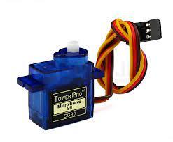
Servo Motor

Description
The servo motor controls the position of the shaded sliding window, adjusting the amount of light exposure based on the measured light intensity and user-defined parameters.
Features
- Precise angle control
- PWM control interface
- High torque
Technical Specifications
- Operating Voltage: 5V DC
- Operating Current: 500mA
- Rotation Angle: 180 degrees
- Dimensions: 40mm x 20mm x 38mm
- Weight: 40g
- Interfaces: PWM
- Port Mapping: GPIO 33
- Compatibility: Compatible with standard servo motor libraries.
- Environmental Requirements: Operating Temperature: 0°C to 55°C
- Installation Instructions:
- Connect the servo motor's control wire to GPIO 33 on the ESP32 development board.
- Connect the servo motor's power wire to 5V and the ground wire to GND.
- Maintenance and Support: No specific maintenance is required.
- Troubleshooting: Verify proper power supply and connections. Check the servo motor's functionality using a servo motor tester.
- References: Arduino
Setting Up Hardware


Connect your hardware components to ESP32 as follow
OLED Display (SSD1306)
Connect the SDA and SCL in OLED display to 21 and 22 pins in ESP32
Then the VCC and GND in OLED display should be connected to 3.3v and GND pins in ESP32 as given in the diagram
- SDA - GPIO21
- SCL - GPIO22
Buzzer
Connect the Positive pin Buzzer to 25 in ESP32 and Connect remaining pin in Buzzer to GND
- GPIO25
Push Buttons
For each button,
Connect one end to a resister and the remaining end of resister to 3.3v
Connect the remaining pin in same side to GND
Connect the opposite pin which connected to resister to ESP32 board as given below
- Menu Button - GPIO23
- Go Forward Button - GPIO5
- Go Backward Button - GPIO18
- Cancel Button - GPIO19
Light Dependent Resistors
For LDR you can connect one of the pins in LDR to GND and other one to one the following
- Left LDR - GPIO35
- Right LDR - GPIO34
Servo Motor
For Servo motor you have to connect VCC(Red) to 3.3v and GND(Brown) to GND and the remaining pin to the 33 in ESP32
- GPIO33
Understanding How It Works
Software Architecture
Architectural Overview
The MediBox software architecture follows a modular design, dividing the system into distinct functional components
Hardware Abstraction Layer
This layer encapsulates the hardware-specific functionalities, providing an abstract interface for interacting with the ESP32 peripherals (OLED, buzzer, buttons, LDRs, servo motor).
Sensor Management
This component handles data acquisition from the DHT sensor and LDRs, processing and storing the collected information.
Alarm Management
This module manages the alarms, allowing users to set, disable, and be alerted by alarms using the buzzer.
Time Management
This component handles time synchronization with an NTP server, incorporating user-defined time zone offsets.
User Interface:
This layer manages the user interaction with the system through the OLED display and buttons.
Communication Management
This component handles communication with the MQTT broker, publishing sensor data and receiving control commands for the servo motor.
Hardware Abstraction Layer
This layer provides an abstraction for interacting with the hardware, simplifying the software design and allowing for easy adaptation to different hardware configurations.
OLED Display
Initialized using the Adafruit_SSD1306 library, configuring screen dimensions, reset pin, and I2C address
TwoWire wireInterfaceDisplay = TwoWire(0);
Adafruit_SSD1306 display(SCREEN_WIDTH, SCREEN_HIEGHT, &wireInterfaceDisplay, OLED_RESET);
Functions for text manipulation, drawing shapes, and displaying bitmaps are provided by the library.
Example usage
display.clearDisplay();
display.setTextSize(2);
display.setTextColor(SSD1306_WHITE);
display.setCursor(22, 24);
display.println("MediBoX");
display.display();
Buzzer
Controlled using the ledcWriteTone function, which allows for generating tones at specific frequencies
ledcAttachPin(BUZZER, 0); // Attach buzzer pin to LEDC channel 0
ledcWriteTone(0, 880); // Generate a tone at 880 Hz
delay(100); // Tone duration
ledcWriteTone(0, 0); // Turn off the buzzer
Buttons
Pin modes are set as inputs with internal pull-up resistors
pinMode(MenuInterruptPin, INPUT_PULLUP);
Interrupt handling is implemented for the menu button using attachInterrupt
attachInterrupt(MenuInterruptPin, menuISR, RISING);
LDRs
Analog values are read using analogRead and converted to illuminance (lux) using a formula based on voltage and resistance
float calculateLuxValue(float sensorValue) {
    float voltage = sensorValue / 4096.0 * 3.3;
    float resistance = 10000 * voltage / (3.3 - voltage);
    float lux = pow(RL10 * 1e3 * pow(10, GAMMA) / resistance, (1 / GAMMA));
    if (lux >= 10000) return 1;
    return lux / 10000;
}
Servo Motor
Controlled using the Servo library, allowing for setting the servo motor angle:
Servo servo;
servo.attach(SERVO_MOTOR_PIN);
servo.write(0); // Set the servo angle to 90 degrees
Sensor Management
This component manages data acquisition from the sensors, ensuring that sensor readings are properly processed and utilized within the system.
DHT Sensor
The DHT library simplifies reading temperature and humidity data
DHT dht(DHTPIN, DHTTYPE);
dhtData.temperature = dht.readTemperature();
dhtData.humidity = dht.readHumidity();
Warning conditions are checked against pre-defined thresholds, triggering alerts on the OLED and through the buzzer if necessary
bool handleWarning(DHTData dhtData) {
    bool warn = false;
    if (dhtData.temperature >= TEMPURATION_UPPER_LIMIT || dhtData.temperature <= TEMPURATION_LOWER_LIMIT) {
        // Display warning on OLED
        warn = true;
    }
    // Similar logic for humidity
    return warn;
}
LDRs
Left and right LDR readings are compared to determine the maximum light intensity
readLDRValues(&ldrvalue);
if (ldrvalue.leftLDRValue > ldrvalue.rightLDRValue) {
    ldrvalue.maximumValue = roundf(ldrvalue.leftLDRValue * 1000.0) / 1000.0;
    ldrvalue.isLeftLDRHigh = true;
} else if (ldrvalue.leftLDRValue <= ldrvalue.rightLDRValue) {
    ldrvalue.maximumValue = roundf(ldrvalue.rightLDRValue * 1000) / 1000.0;
    ldrvalue.isLeftLDRHigh = false;
}
Alarm Management
This module provides functionalities for setting, managing, and triggering alarms within the system.
Alarm Configuration
Allows users to set alarm times (hours and minutes) using the OLED interface.
Saves alarm configurations to non-volatile memory using the Preferences library:
Preferences preferences;
preferences.begin(alarm->time->time_name, false);
preferences.putUInt("hour", alarm->time->hours);
preferences.putUInt("minute", alarm->time->minutes);
preferences.end();
Calculates the remaining time (in seconds) until an alarm triggers:
long timeNowInSeconds = timeinfo.tm_hour * 3600 + timeinfo.tm_min * 60 + timeinfo.tm_sec;
long alarmTimeInSeconds = (alarm->time->hours * 3600 + alarm->time->minutes * 60);
if (alarmTimeInSeconds < timeNowInSeconds) {
    alarmTime = 86400 - timeNowInSeconds + alarmTimeInSeconds;
} else {
    alarmTime = alarmTimeInSeconds - timeNowInSeconds;
}
alarm->alarmTimeInSeconds = alarmTime;
Alarm Triggering
Continuously checks if the current time matches any set alarms.
Activates the buzzer using ledcWriteTone when an alarm triggers, generating a distinct alarm tone.
Displays an alarm notification on the OLED screen, reminding users to take their medication.
The isAlarm function iterates through all alarms and checks if the current time matches the alarm time.
If an alarm needs to be triggered, it sets the isRinging flag to true and activates the buzzer.
void isAlarm(Alarm *alarms[]) {
    getTime(&timeinfo);
    for (int i = 0; i < 3; i++) {
        if (alarms[i]->isSet && timeinfo.tm_hour == alarms[i]->time->hours && timeinfo.tm_min == alarms[i]->time->minutes) {
            alarms[i]->isRinging = true;
            ringingAlarm = true;
            alarms[i]->isSet = false;
            // Activate Buzzer here
            ledcWriteTone(0, 880);
        }
        // ...
    }
}
Alarm Disabling
The disableAlarm function sets the isSet and isRinging flags of an alarm to false, effectively disabling it.
It also saves the updated state to non-volatile memory.
void disableAlarm(Alarm *alarm, Preferences *preferences) {
    alarm->isSet = false;
    alarm->isRinging = false;
    saveAlarm(alarm, preferences); // Save updated state
}
Time Management
This component manages time synchronization and allows for user-defined time zone adjustments.
Time Synchronization
The setTime function synchronizes the system time with an NTP server.
It uses configTime with the offset obtained from the offset struct and the daylightOffset_sec.void setTime(Time offset, int daylightOffset_sec, const char *ntpServer) {
    int offsetInSeconds = offset.hours * 3600 + offset.minutes * 60; // Calculate total offset in seconds
    messageDisplay("Time", "Configuring..", timeConfig);
    configTime(offsetInSeconds, daylightOffset_sec, ntpServer);
    // ...
}
Time Zone Offset
Users can configure a custom time zone offset from UTC, which is used in the configTime function.
The offset struct holds the user-defined time zone offset, which is used in the configTime function.
The offset is loaded from and saved to non-volatile memory using Preferences.
Time offset = {3, "Offset", 5, 30}; // Example initial offset

void loadOffsets(Time *offset, Preferences *preferences) {
    preferences->begin(offset->time_name, false);
    offset->hours = preferences->getUInt("hour", offset->hours);
    offset->minutes = preferences->getUInt("minute", offset->minutes);
    preferences->end();
}

void saveOffset(Time *offset, Preferences *preferences) {
    // ... Similar to loadOffsets, but uses putUInt to save
}
User Interface
This layer manages user interactions with the system through the OLED display and buttons.
Menu Navigation
The handleMainMenu function manages the main menu displayed on the OLED.
It uses the selectedFrame struct to track which menu option is currently selected.
The goForwardButton and goBackwardButton are used to scroll through menu options.
bool handleMainMenu(Alarm *alarms[], Time *offset, SelectedFrame *selectedFrame, Menu *menu, Button *menuButton, Button *goForwardButton, Button *goBackwardButton, Button *cancelButton) {
    pooling(goForwardButton, goBackwardButton, cancelButton);
    if (goForwardButton->pressed) {
        if (selectedFrame->frameStartY < 50) {
            selectedFrame->frameStartY += 10;
            selectedOption = (MenuOptions)(selectedOption + 1);
        } else {
            selectedFrame->frameStartY = 10;
            selectedOption = Alarm_01;
        }
        // ...
        displayMenu(selectedFrame, menu);
    }
    // ... Similar logic for goBackwardButton and other buttons
}
Alarm Configuration
Functions like adjustAlarmHours and adjustAlarmMinutes are used to handle button presses and increment or decrement the alarm hours and minutes:
if (goForwardButton->pressed) {
    if (alarm->time->hours < 23) {
        alarm->time->hours++;
    } else {
        alarm->time->hours = 0;
    }
    goForwardButton->pressed = false;
    goForwardButton->numberKeyPresses = 0;
    displayAlarm(alarm->time->hours, "Hours");
}
Time Zone Configuration
The user can set the time zone offset using the menu navigation.
Functions like adjustTimeZoneHours and adjustTimeZoneMinutes handle the incrementing and decrementing of the time zone hours and minutes based on button presses.
void adjustTimeZoneHours(Time *time, Button *menuButton, Button *goForwardButton, Button *goBackwardButton, Button *cancelButton) {
    pooling(goForwardButton, goBackwardButton, cancelButton);
    if (goForwardButton->pressed) {
        if (time->hours >= -13 && time->hours < 15) {
            time->hours++;
        } else if (time->hours >= 15) {
            time->hours = -13;
        } else if (time->hours < -13) {
            time->hours = 15;
        }
        // ...
        displayTimeZone(time->hours, "Hours");
    }
    // ... Similar logic for decrementing and handling other buttons
}
Warning Display
Utilizes the OLED display to present warning messages if temperature or humidity levels exceed pre-defined thresholds, ensuring that users are aware of potential issues.
The handleWarning function checks for temperature and humidity exceeding predefined limits. If a warning condition is detected, it updates the OLED display with relevant information.
bool handleWarning(DHTData dhtData) {
    bool warn = false;
    if (dhtData.temperature >= TEMPURATION_UPPER_LIMIT || dhtData.temperature <= TEMPURATION_LOWER_LIMIT) {
        display.setCursor(0, 48);
        display.println("Temperature: " + String(dhtData.temperature) + "C"); // Display warning message
        warn = true;
    }
    if (dhtData.humidity >= HUMIDITY_UPPER_LIMIT || dhtData.humidity <= HUMIDITY_LOWER_LIMIT) {
        display.setCursor(0, 56);
        display.println("Humidity: " + String(dhtData.humidity) + "%"); // Display warning message
        warn = true;
    }
    // ...
    return warn;
}
Status Display
Displays essential information, including the current time, date, and environmental conditions (temperature, humidity) on the OLED screen
display.setCursor(0, 48);
display.drawRect(12, 14, 104, 28, SSD1306_WHITE);
display.setCursor(34, 0);
display.println(&timeinfo, "%d-%m-%Y");
display.setCursor(16, 20);
display.setTextSize(2);
display.println(&timeinfo, "%H:%M:%S");
Communication Management
This component manages communication with the external world using the MQTT protocol.
MQTT Client
Establishes a secure connection with the MQTT broker using the WiFiClientSecure and PubSubClient libraries
WiFiClientSecure espClient;
PubSubClient client(espClient);
espClient.setCACert(root_ca);
client.setServer(MQTT_SERVER, MQTT_PORT);
Publish Sensor Data
Publishes sensor readings (LDR values, temperature, humidity) to specified topics on the MQTT broker using client.publish
char buffer[256];
serializeJson(doc, buffer); // Serialize sensor data into JSON format
client.publish(LDR_TOPIC, buffer);
Subscribe to Servo Control:
Subscribes to a designated topic to receive control commands for the servo motor from the MQTT broker using client.subscribe
client.subscribe(SERVO_TOPIC);
The callback function (callback) processes received commands and controls the servo motor accordingly:
void callback(char *topic, byte *payload, unsigned int length) {
    String incommingMessage = "";
    // ... process received message ...
    if (topic_Str == SERVO_TOPIC) {
        handleServoMotor(incommingMessage, &servo);
    }
}
Setting Up All Together


First clone the github repository in here
Then go to include folder and make a new file named Certificate.h
In this you need add to SSL for the your private MQTT broker (Since here we are using Secured Connection)
If you don't have a certificate just go to the emqx and create a new account
After that go to the deploment tab as here
and create a new instance of MQTT broker
Once you have created instance you can click the instance and go to the settings as follow
From here you have to create a username and password for the your ESP32 and Node Red Dashboard
By Default in given code snippet :
Credentials for Node Red dashboard
- Username - Dashboard
- Password - Sample@123
Credentials for Node Red dashboard
- Username - Esp_client
- Password - Sample@123
Then go back to the instance and get the Address of your MQTT client and download the certificate
Go Back to the Certificate.h and add your certificate as follow in Certificate.h
const char *root_ca = R"EOF(
    -----BEGIN CERTIFICATE-----
// Add your certificate here
-----END CERTIFICATE-----
)EOF";
You can find full article about to how to connect ESP32 to EMX in here
Configuring Node Red Dashboard


Run node red according to the above guideline ( Node Red Offical ) and go the import option in top right corner as given in the photo
Import the the dashboard.json from dashboard folder
Setup the MQTT server configurations given in the photo
Go to the Security tab in the MQTT node and set username password which you get for the dashboard
Deploy the flow and go the http://127.0.0.1:1880/ui/ then you will see the dashboard
Configuring ESP32

Go to the VS Code editor and open the Definitions.h
Edit the MQTT server as here
#define MQTT_SERVER "example.com"
#define MQTT_PORT 8883
#define MQTT_CLIENT_ID "ESP32-0101"
Then open the main.cpp in src folder and change according to your configurations
// Set ssid and password for the wifi
const char *ssid = "Sample";
const char *password = "1234567890";


// Set mqtt user credentials for the MQTT Connection
const char *mqtt_username = "Esp_client";
const char *mqtt_password = "Sample@123";
Once you have configured settings just upload the code snippet to ESP32
Finishing Up


Now all are working !
So go to menus and different options in the menus
Set the alarms
Set the time zones
You will notice all are working if you have followed this article correctly !
Also go to the node red dashboard you will see the tempurature and other parameters
Resources
The whole project you can clone from here
Just Upload it !
Conclution
MediBox is not just a medication reminder; it's a statement about harnessing time for a healthier life. By building your own MediBox, you're not just constructing a device; you're joining a movement that recognizes the importance of time in healthcare.
Through its precise timekeeping, customizable alarms, and environmental monitoring, MediBox exemplifies the contest's theme. It transforms the abstract concept of time into a tangible tool for managing medication, making every second count towards improved well-being.
And that's it! Please ask questions if you have them.
Make Time, Make Health Easier. Build your own MediBox and join the "Making Time" revolution!