Your Own Flashing Kolam That Traces a Euler Circuit (a Project on Art, Electronics and Ethnomathematics)
by suryadessirier in Circuits > Electronics
807 Views, 11 Favorites, 0 Comments
Your Own Flashing Kolam That Traces a Euler Circuit (a Project on Art, Electronics and Ethnomathematics)

https://www.youtube.com/shorts/-bZ4oomZIcI
Introduction:
Hello, I am a student in 10th grade and love dabbling in arts/crafts and electronics. I live in a small town in southern India where the art of Kolam making has been a morning ritual for hundreds of years. Kolams are decorations made in front of our homes with rice flour to beautify the entrance of the home. These geometric patterns are offerings to Bhudevi or Mother Earth and also feed insects. An example of such a Kolam is shown below.

(source-Kolam: Ritual Art that Feeds a Thousand Souls Every Day, by Gayathri Ramachandran | DailyGood)
Besides being beautiful to look at, Kolams encode a lot of mathematics including Euler circuits, symmetry, fractals etc. Kolams have been used by scientists in the programming of computer languages as well. My project was inspired by the kolams I see everyday in front of homes. I explored the tracing of Euler circuits in kolams with a flashing LED chaser light made of Neo pixels, and programmed using the Arduino Uno.
What is a Euler circuit?
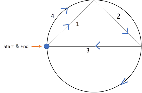
A Euler circuit refers to a path or trail that goes over a shape without repeating an edge twice. It starts and ends at the same place. When you were younger you might have traced shapes without lifting your pencil and ended at the same place where you started. Well, you were tracing Euler circuits.
Why are Euler circuits important?
People use Euler circuits in their everyday life, so that they don’t have to retrace their previous steps and can save time and energy. For example, the garbage removal man, mailman, parking meter man, subway inspector all use Euler circuits to optimize their working routes. Euler circuits are also used in optimizing plumbing routes, electricity circuits in homes, sewerage routes in big cities, in computer networks and in the study of computer languages
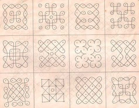
I have used a very simple kolam for my project but, you are free to choose any kolam that you like. I have provided a couple images below to help you with that.
Supplies
Materials:
1.Neo pixels, WS2812b link
2. Breadboard
3. Wire to solder to neopixels
4. Square general purpose PCB circuit board to attach neopixels to
5. Soldering iron: with flux and solder
6. Arduino Uno
7. 1000 microfarad capacitor at 25V
8. 470 Ohm resistor
9. Arduino cable
10. Cable with a USB jack on one side and the other side should be cut to expose the positive and negative ends to insert into breadboard
11. Cable with USB jack and the other end cut and a barrel jack soldered to its positive and negative end.
11. Buck converter adjusted to step down the incoming voltage to 5 volts link
12. Battery pack link
13. Jumper wires
Let's start building!
Prepare Your Wires

Cut pieces of wires of approximate length 2.5 cm. Six pieces of wire are needed for each neo pixel. Once you have as many as you need for the pattern you are following, straighten them out, and bend one side of the piece of wire like in the picture above.
Prepare Your Neo Pixels


Now, take you neo pixels, and observe the behind.
You will see six metal points, with some markings around them.
In the picture above, the top two points are the positives for (in and out). The middle pair are the data pins: in, and out respectively as marked on the picture. The bottom most pair are the negatives (for in and out).
You will have to solder the bent part of the piece of cut wire to each metal point. The neo pixel after soldering should look like the pic shown above.
Testing Your Neo Pixels


Before assembling anything on the PCB board, testing is needed to ensure that the neo pixels are working. I made batches of 8 neo pixels at a time and tested them by daisy chaining them on the breadboard using the code attached below.
Upload the code to your Arduino:
Here are the connections you will use for your testing as well as for the final project.
Take your wired neo pixels, and daisy chain 8 of them on your breadboard.
Connect the positive OUT of the first neo pixel to the positive IN of the second, the negative OUT of the same to the negative IN of the second, and the Data OUT of first to the Data IN of the second. Similarly, the remaining 6 neo pixels connect in a consecutive manner starting from the second neo pixel.
To smoothen out any current spikes in the first neo pixel, a capacitor is attached to the positive IN and negative IN of the neo pixel on the breadboard. Also, the data channel of the first neo pixel is protected by placing a 470 Ohm resistor between it and the Arduino.
A jumper wire connects the resistor to a digital output pin on the Arduino. I have used digital IO pin 13 on the Arduino to control the LEDs.
The battery pack has 2 USB connections. I used one of the USB connectors to power the LEDs and the other USB connection to power the Arduino. To ensure only 5V was being supplied to the LEDs, a step down buck converter was placed between the LEDs and the battery pack as shown in the circuit drawing above.
If all your neo pixels are working, they should all light up.
Trace Your Kolam


Now you can draw your Kolam on the PCB board. Here is the one I used.
Attach Your Neo Pixels


Before you attach the neo pixels to the PCB board, make sure you determine the Euler circuit in the Kolam. This means, picking a start point on the Kolam and tracing it with a pencil so you can draw the entire Kolam without lifting the pencil. The end point of the circuit trace will coincide with the start point of the circuit. You can see the Euler trace shown in arrows in the figure drawn on PCB board. The start could be anywhere on the Kolam as long as the rules of the Euler circuit are met. Now attach the neo pixels along the traced Euler circuit. Place each neo pixel on the board by slipping the 6 wires into the holes of the PCB board. Connect to the next neo pixel as described previously in step 3
Remember to test every time you add a neo pixel (if one neo pixel doesn't work, none of the others following it will),
The final product should look something like the picture on the left, above.
At the back, I put a heat sleeve on each of the wires crossing other ones, so that there was no shorting. Also, on the first neo pixel, longer jumper wires were connected at the IN junction of the positive, negative and data channel so they could be directly inserted into the breadboard.
Tracing the Euler Circuit in the Kolam

Upload this code to your Arduino:
Similar to the breadboard connection, ensure the first neo pixel is protected with a capacitor, a resistor and a buck converter as shown in the figure below. The battery pack power supply was used to power both the LEDs and the Arduino using the 2 USB connectors on the power pack as described in step 3.
The uploaded code will turn on the LEDs connected to each other one by one, until all of them are lit. Then, it will turn them off in the reverse direction tracing the Euler circuit from start to end.
https://www.youtube.com/shorts/-bZ4oomZIcI