Yongnuo 622-C Battery Mod
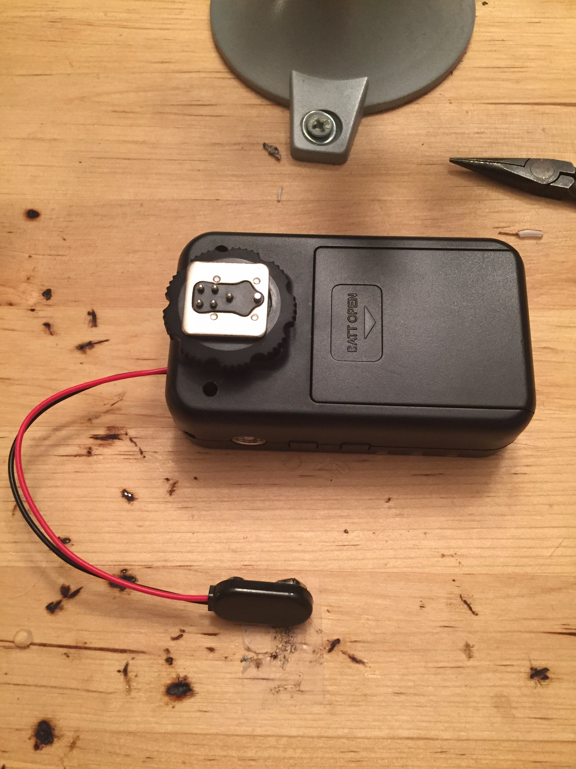
The Yonguno 622-C remote triggers are an inexpensive solution for firing a remote flash without cables. Yonguno specs list the standby time for two AA batteries at 60 hours. Integrating the Yonguno triggers into my camera trap solution, I need much more than the listed 60 hours, or 2.5 days. By hard wiring an additional battery pack, I can double my run time in the field to 120 hours, or just about 5 days. Perfect for leaving a set up in the woods without worrying about batteries dying and meets my needs for checking on the remote camera setup.
I use the Yongnuo 622-C triggers because you can pick them up used for around $20, and they just work. The buttons are poorly placed where big fingers can inadvertently change settings, but I've used them so many times that I'm aware of their shortcomings. A short time ago, I invested heavily in the Yongnuo triggers purchasing 10 triggers based on my studio photography requirements, not fully understanding their limited continued used standby time of 60 hours.
This Instructable addresses that shortcoming.
The first time I performed this mod, it took me over 30 minutes. I just made this mod to all 10 of my remaining triggers and start to finish was about 5 minutes each.
Step 1: Tools and Materials
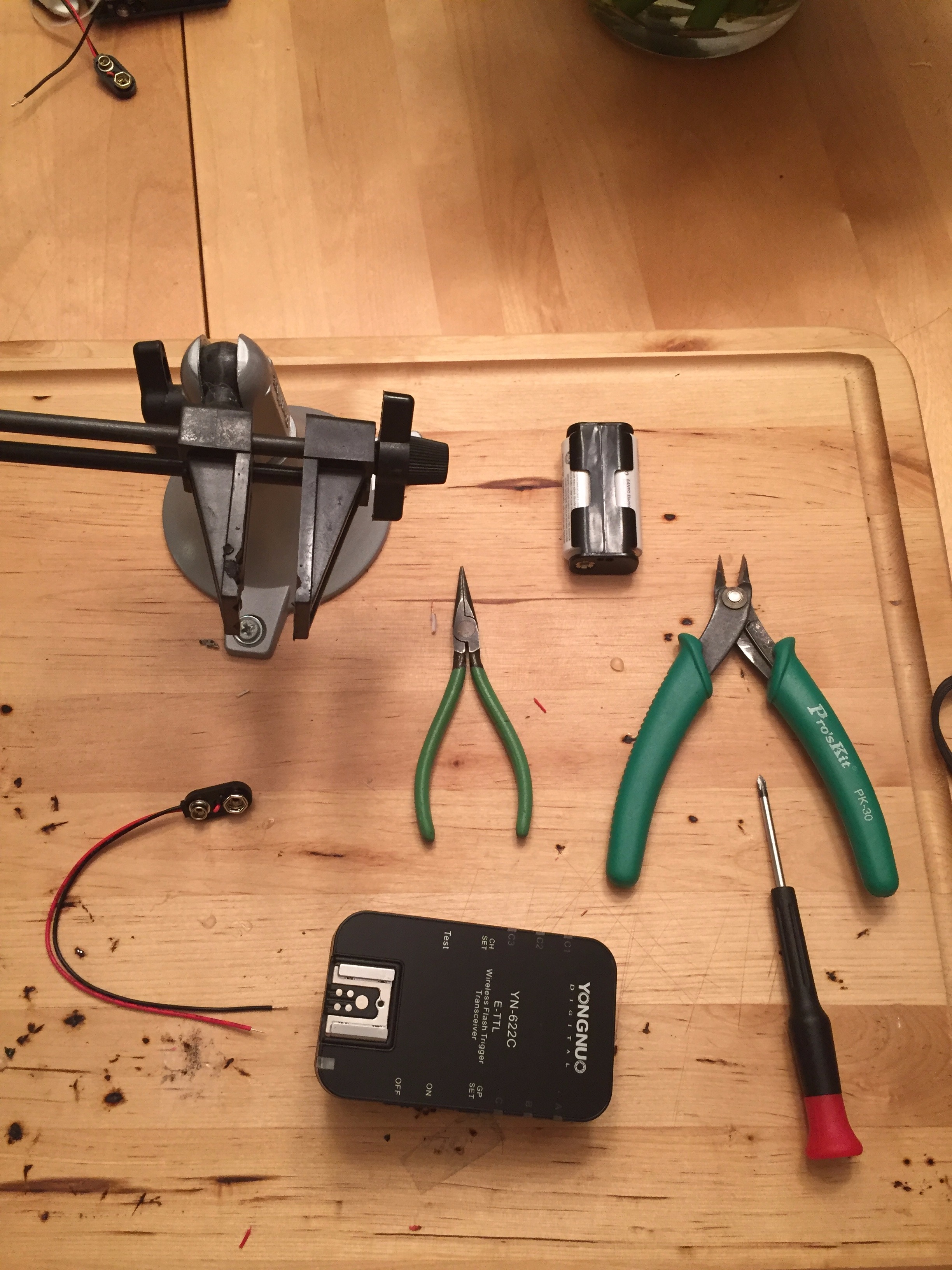
To successfully complete this case you will need the following tools and parts:
- RadioShack Fully Insulated 9V Battery Snap Connectors
- AA battery Pack
- Wire Cutters
- Small Philips head screwdriver
- Small electronics vice
- Needle nose pliers
- Yongnuo 622-C trigger
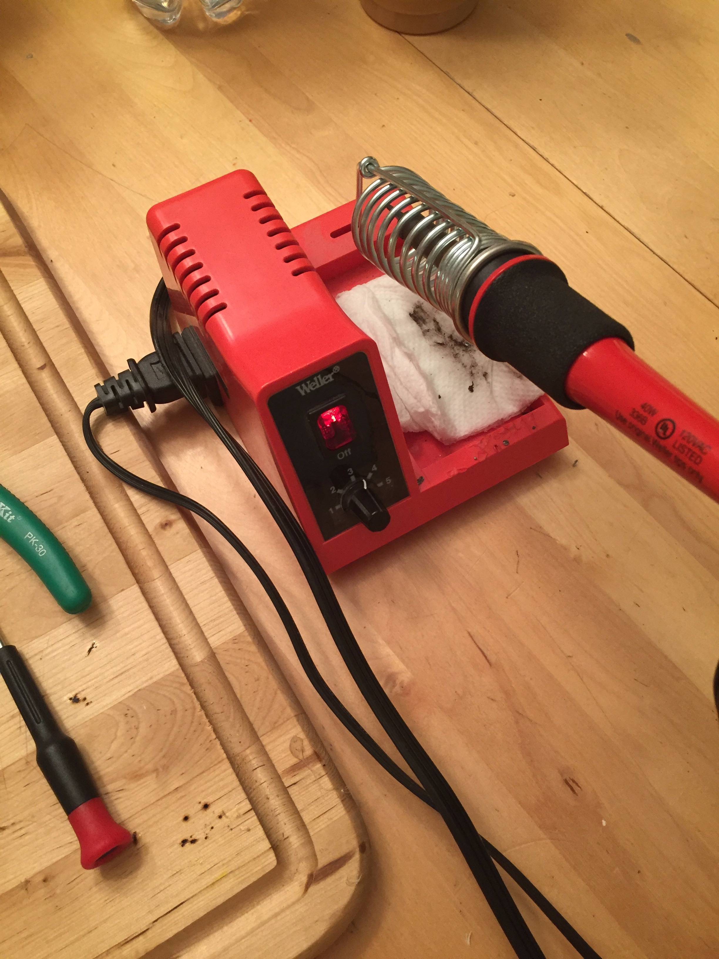
- Soldering Iron
- Solder
Step 2: Removing the Battery Cover
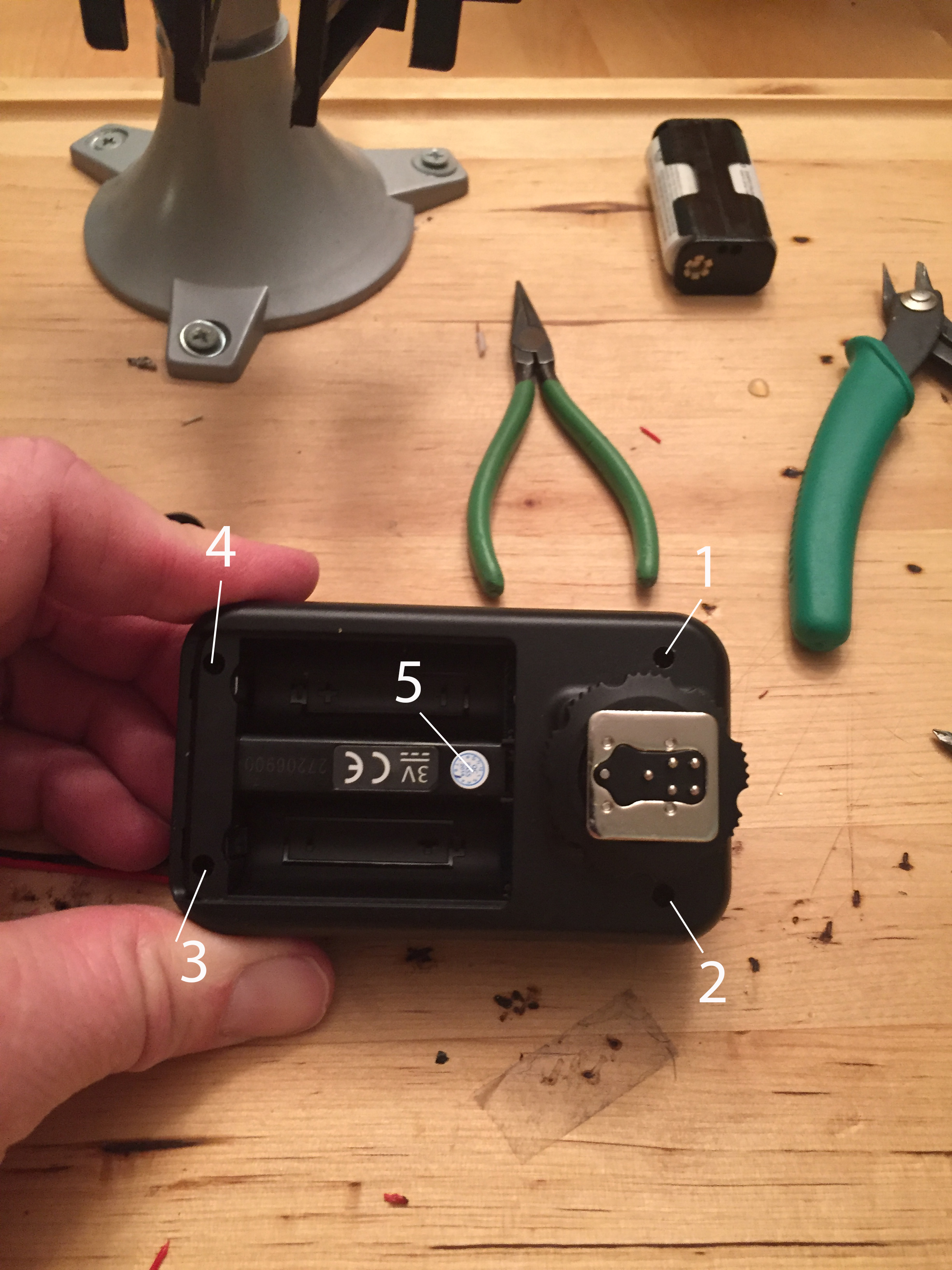
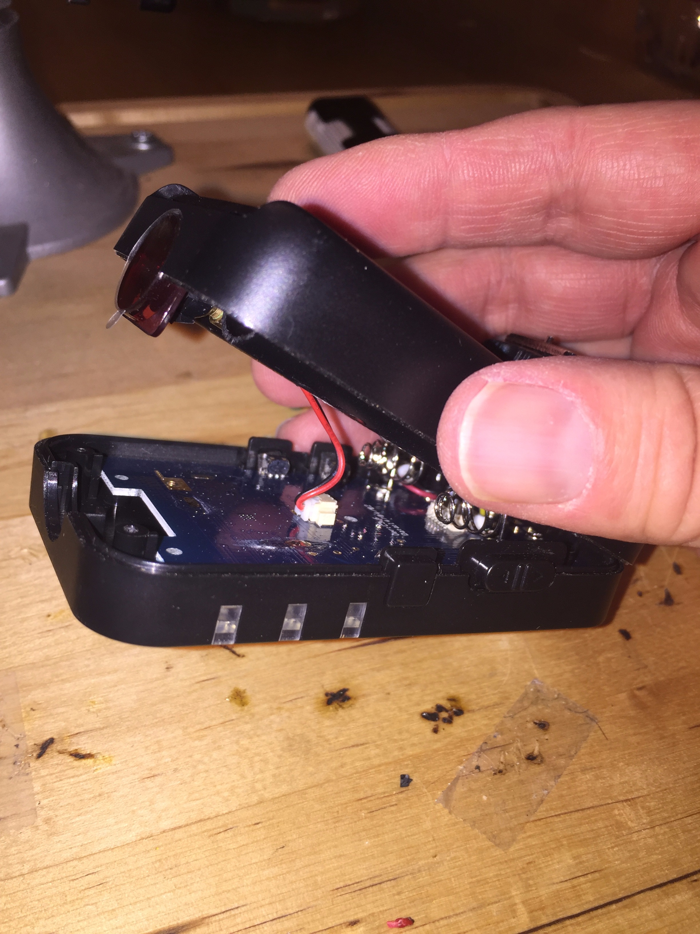
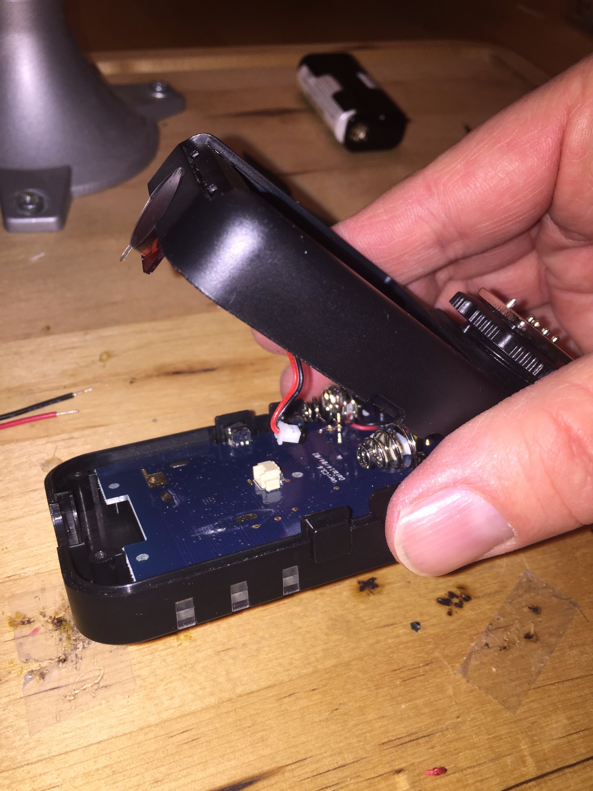
This step describes removing the battery cover so we can access the battery posts. The screws mostly remain in the holes and you can leave them there. Sometimes they pop out, if they do, place them aside.
- Remove the battery case cover by sliding it off.
- Locate and remove the 5 screws as shown. The 5th screw is under the label, do not worry about removing the label.
- Lift the bottom portion (that holds the batteries from the base).
- Locate the connector for the IR sensor and pull it away from the connector (the Red and Black cable that attaches to the motherboard). I use my fingers to pull the cable from the connector, but you may need to use needle nose pliers.
(NOTE: I've made this mod 20 times, but one time the cable that attaches to the IR sensor separated from the sensor. I've been unable to reattach the cable and I've attributed this problem to a manufacturing defect.)
5. You do not have to remove the rear connector as there is enough cables length to work inside the enclosure.
Step 3: Connecting the 9V Battery Snap Connector
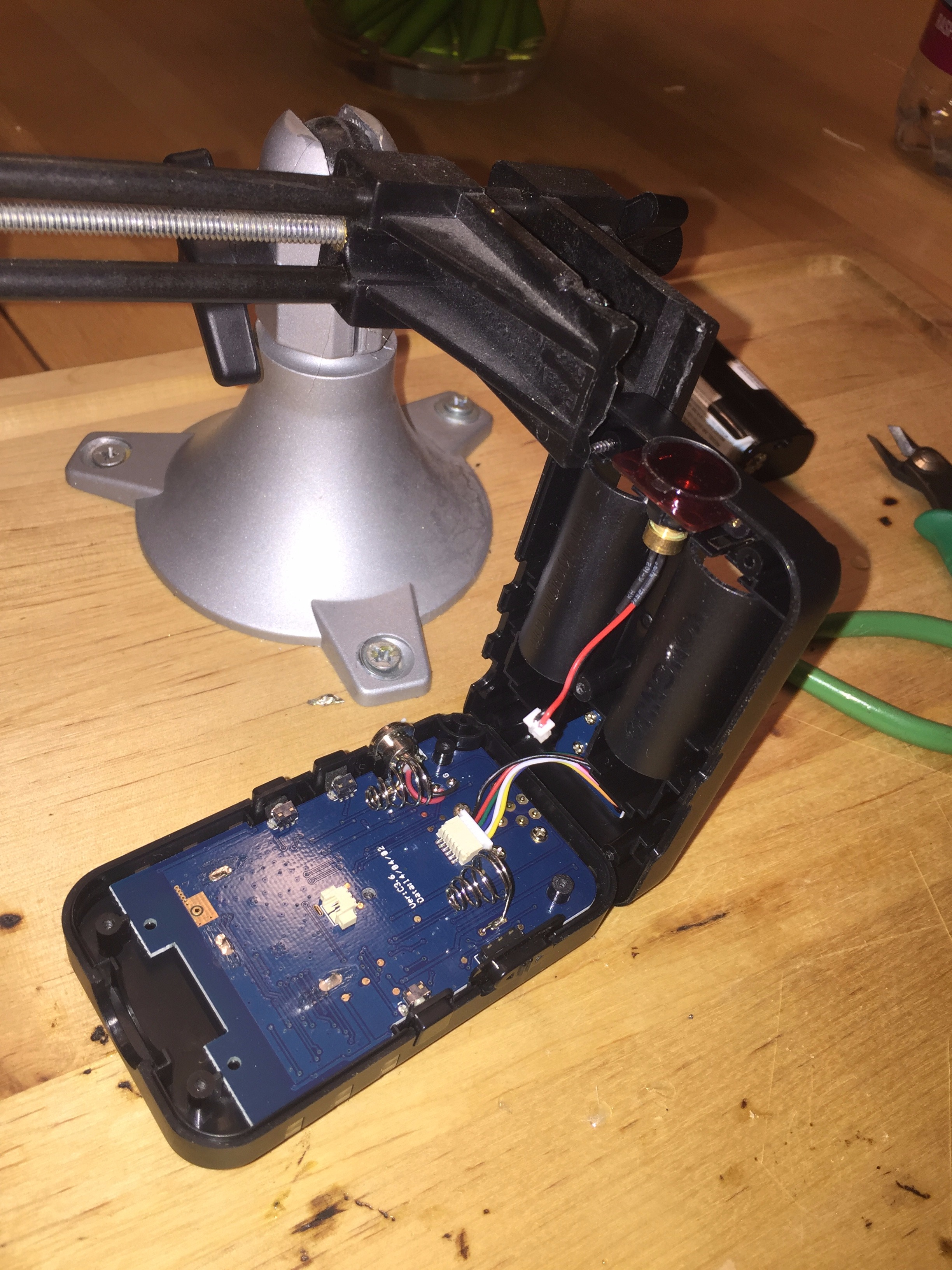
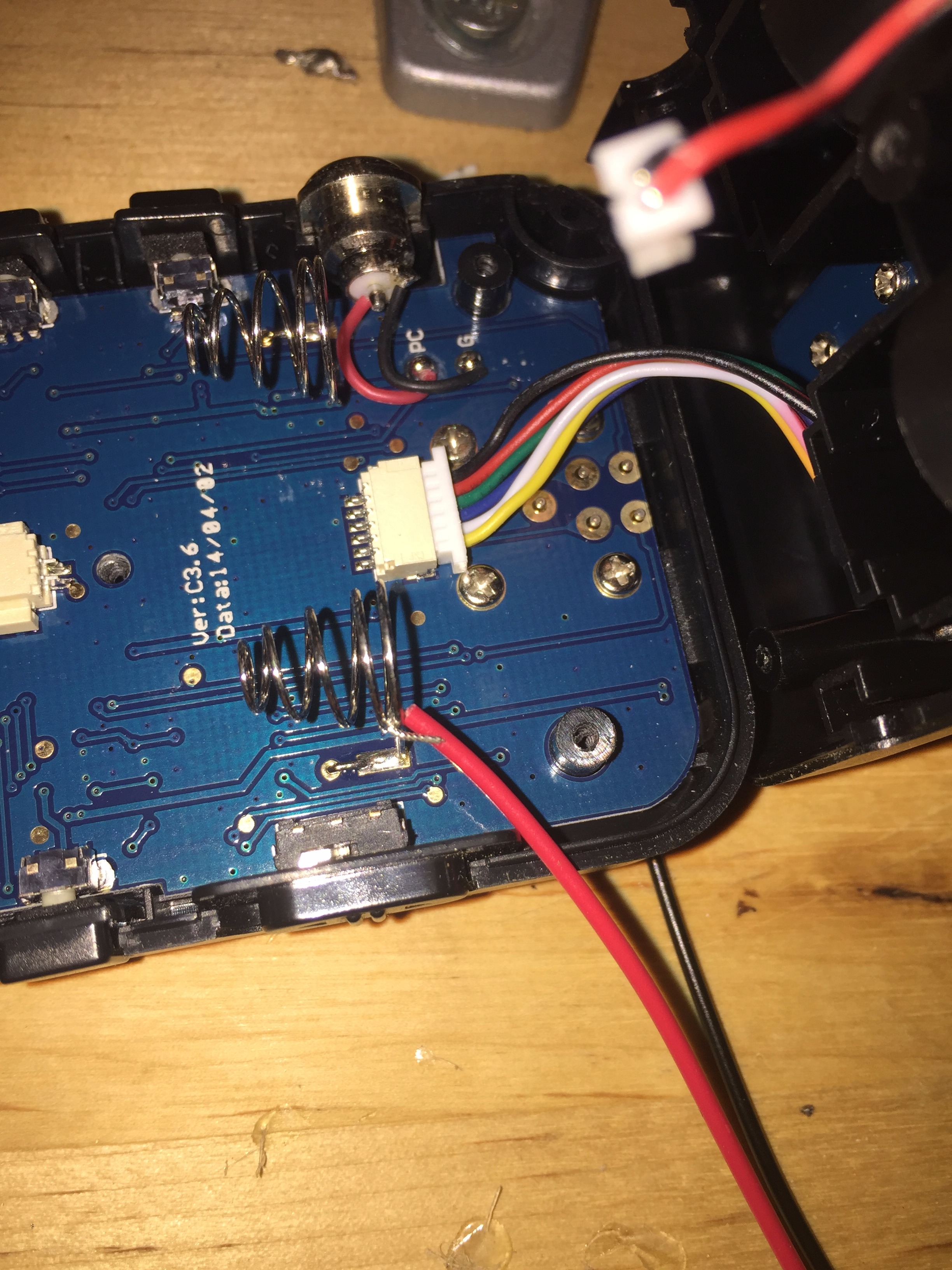
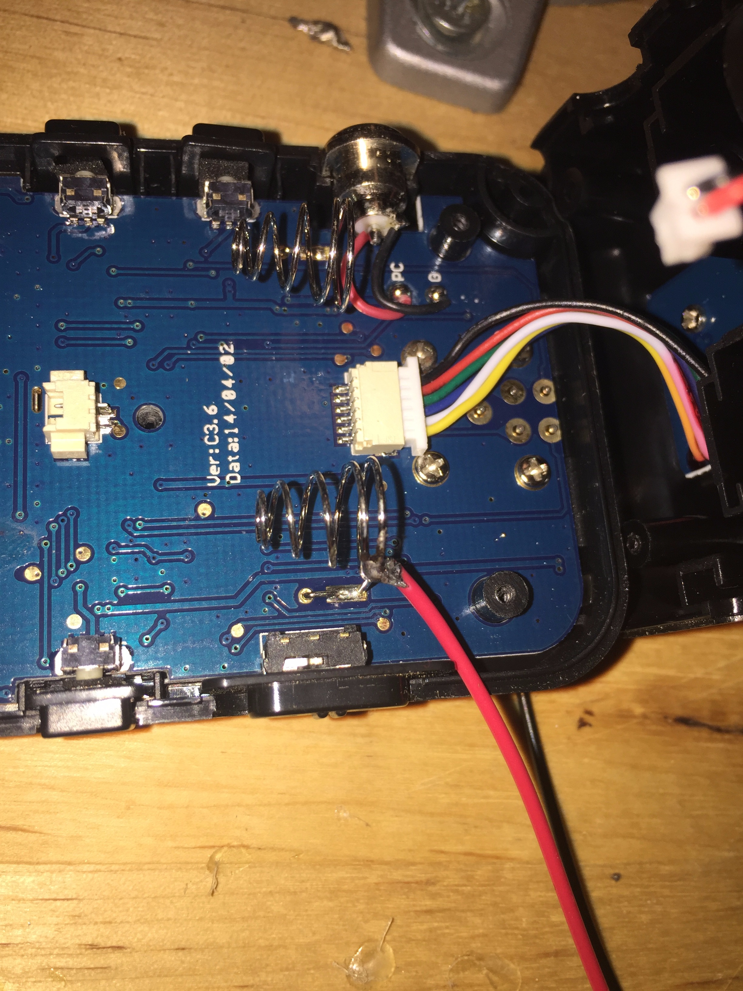
This step involves soldering the battery snap connector to the existing battery terminals.
- Attach the top battery case to a vise to keep it open and out of your way. This is an optional step if you can find a way to work inside the case.
- Check which terminal is positive and negative from the existing battery holder case. In this example with the case aligned as shown in the picture, positive is on the bottom.
- Solder the positive cable as low to the motherboard as you are comfortable. If you make the connection too high, then reattaching the case is a little more difficult. If you have trouble, you may need to trim some of the plastic off where the battery terminal passes through the case.
- Repeat for the negative side.
- Connect the IR connector to the motherboard. I can use my fingers, but use the needle nose pliers if you have trouble getting your fingers in the space.
Step 4: Finishing Up
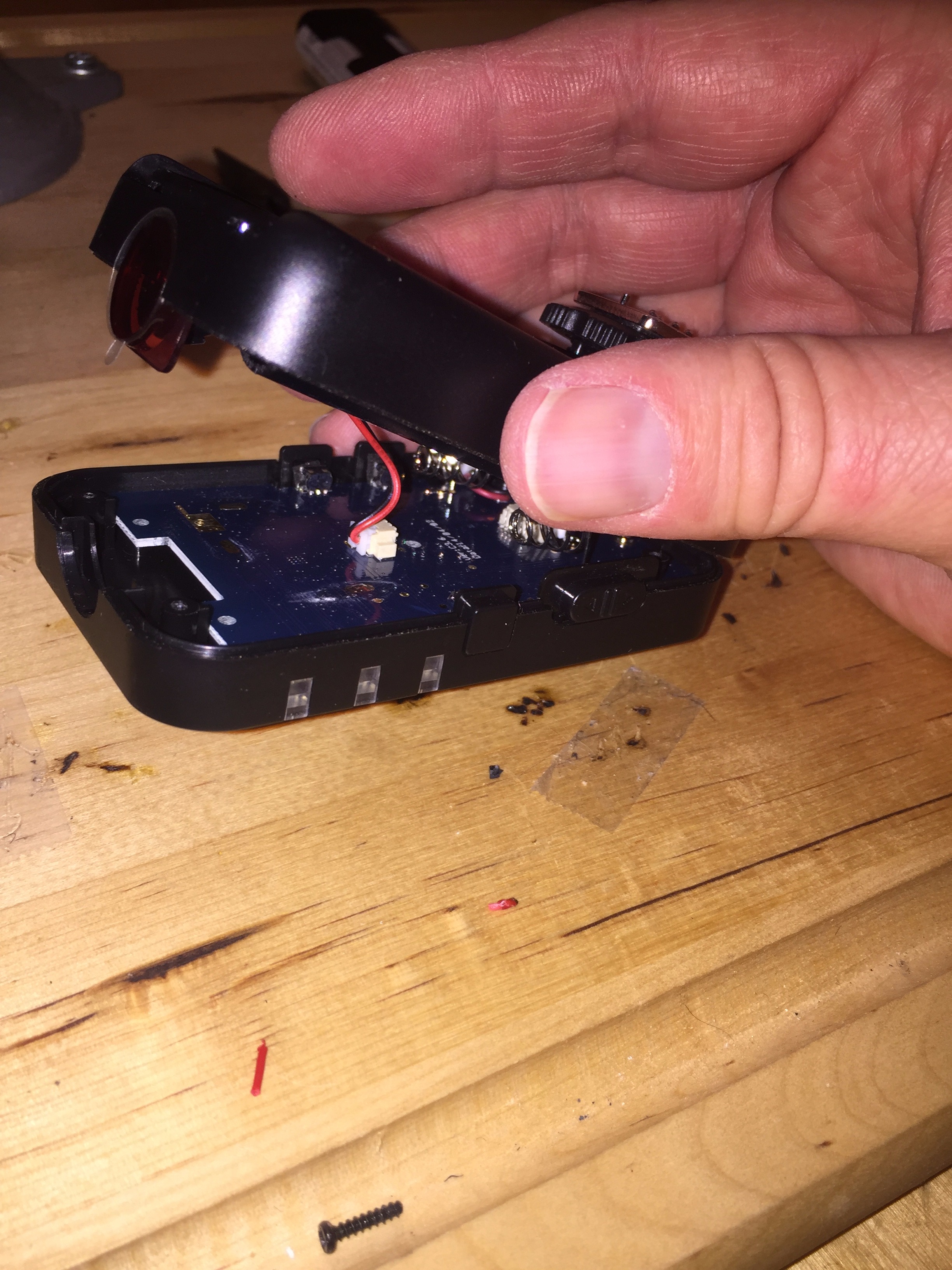
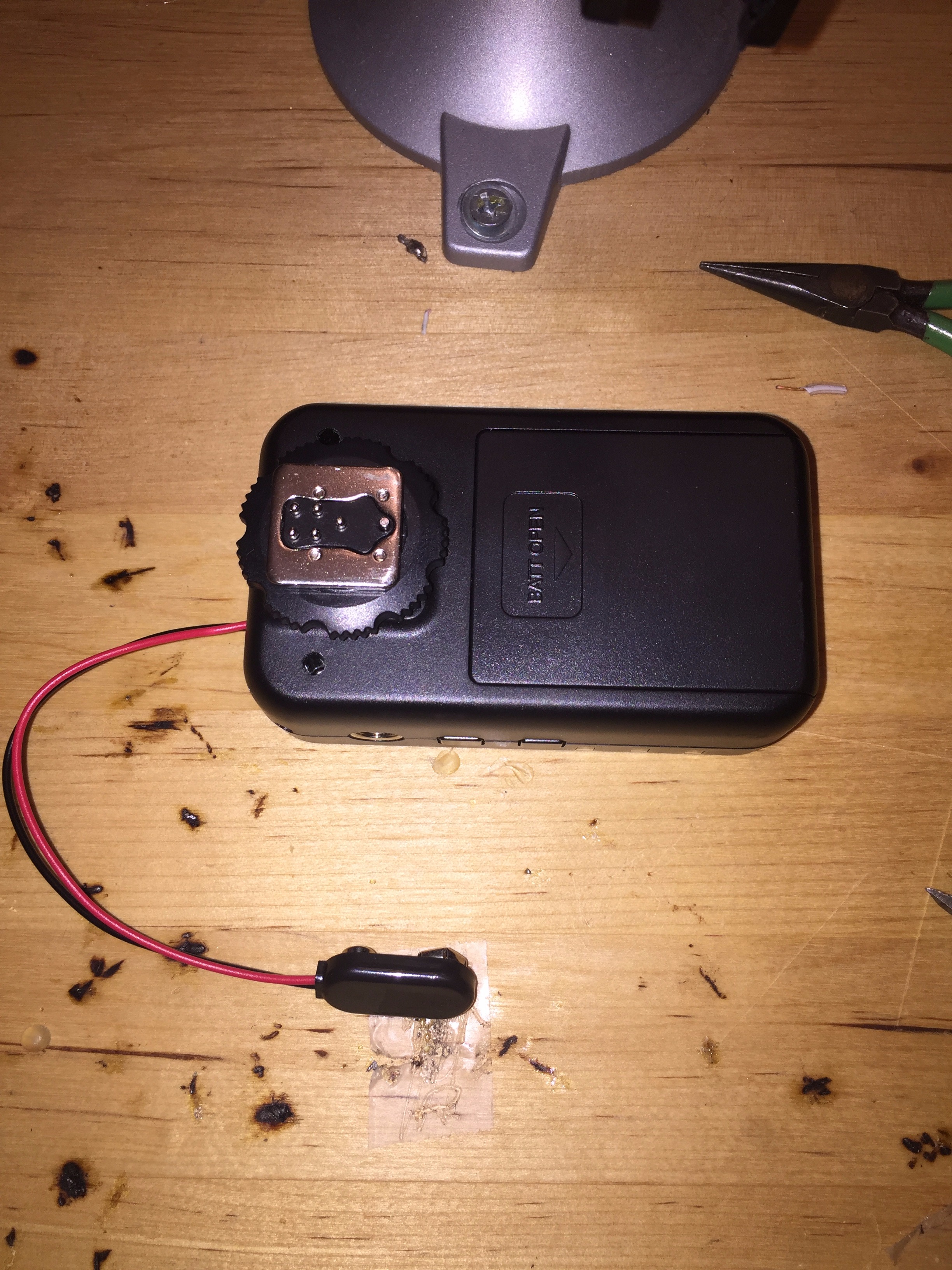
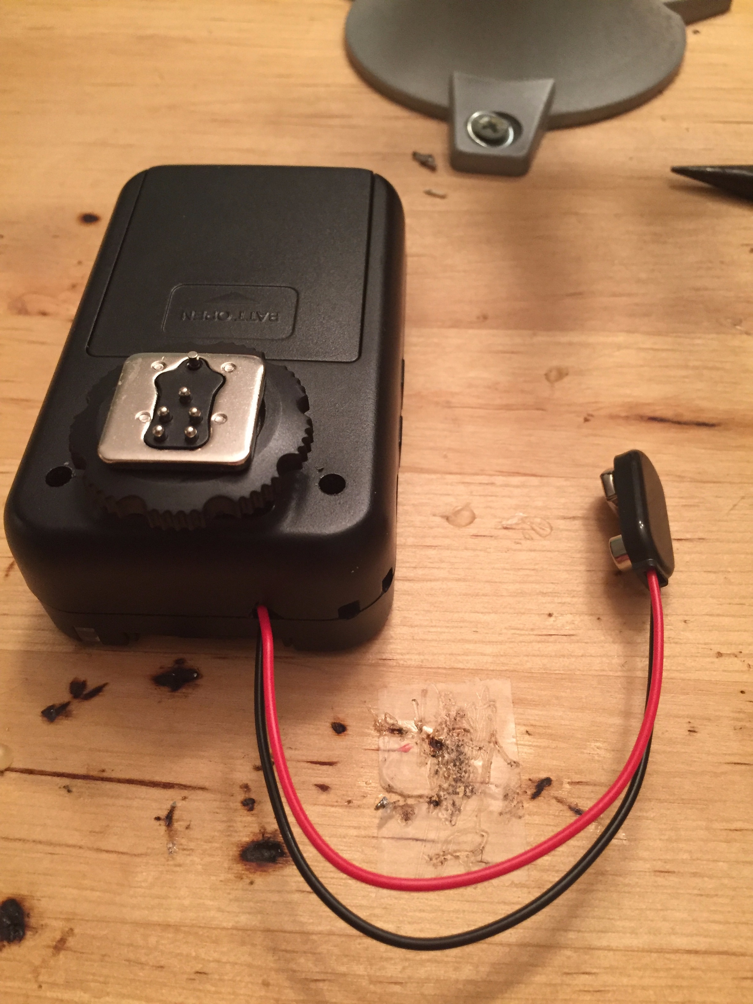
The hard part is done and now we can reassemble the product.
- Check to see if any buttons, switches, connectors, or IR pieces have fallen out during the upgrade. If they have, slide them into the plastic panels in the trigger. They can and will fall out, save yourself a lot of time and frustration by checking now.
- Replace the top battery holder onto the base trigger. Some sliding and slight pressure may be necessary. If you made your battery pack connections too high on the battery posts, you may need to trim some of the plastic so the top and bottom can fit correctly.
- Replace any screws that fell out during the upgrade and tighten all 5
- Attach a AA battery pack to the Yonguno 622-C.
- Push the power switch to the ON position and confirm that the power LED is enabled.
- Before deploying, test the added battery pack with internal batteries.