Wordclock - No Special Tools Required! Easy to Build
by Bad_Wolf_laboratories in Circuits > Clocks
14135 Views, 166 Favorites, 0 Comments
Wordclock - No Special Tools Required! Easy to Build


Hi makers, do you want to own a wordclock?
There are a lot of nice instructions all over the web, but
- You've no access to a 3D printer and cnc machines to cut, laser or mill
- You don't want to waste time and nerves fiddling with itsy-bitsy parts
- You don't want to waste money, if there is an inexpensive solution doing the same
This Instructable is written for makers regardless of which experience level as long as you are familiar with
- A soldering iron
- Arduino IDE with Nodemcu / ESP8266 extension
- Basic wood working
What's new in this Instructable
- How to make a multilayer wood / paper circuit
- How to build a 25x25cm wordclock for less than 40€
- How to make it within 3-4 hours from scratch
- The choice of English or German front panel
- Clock shows IP address at startup
What's not new but cool, anyway
- Wifi connection accesspoint / station
- Getting time from a NTP server
- HTML interface to set display color and time offset for summer/winter
Here we go
Making a wordclock is cool! I've made some in the past using special machines like 3D printer, cnc mill and Silhouette cutting plotter. Each of them took a lot of time to build. Mostly weeding the text mask after cutting was a nightmare!
Reducing to the essential was the order of the day - especially due to Xmas and birthdays came up and I wanted to build 5 more clocks.
Is there a simple solution possible?
I've not reinvented the wheel, but this Instructable shows a cool approach to build electronic gadgets.
The answer is YES!
Design goals
- Easy and quick to make and use
- Using standard tools and parts
- Assembly without fiddling
- No need for a PCB
- Should be awesome
Summary for the impatient experienced maker
Hi, brothers in mind! Here comes your fast lane - fasten your seat belts, please.
- print the 4 sheets (one of the text masks, separator, electronics and stripes)
- take one MDF board and stick stripes sheet top left orientated on it
- flip the board and stick electronics sheet top right orientated on it
this is called "mainboard" from now on - take second MDF board and stick separator template top left oriented on it
drill 12mm holes now or later - stick copper tape snippets on mainboard stripes
5V, Gnd and data wrap around to electronics - flip mainboard and stick copper tape snippets in this order:
bottom layer (brown), isolation pads (red) and toplayer (green) - cut from LED stripe 1x6, 9x10 and 1x4 LED snippets in an order, to not hit the solder joints
- stick the LEDs on mainboard stripes side
follow the orientation arrows on template and LED stripe - connect with unisolated thin wire LEDs to copper tape
- flip mainboard and stick modules with double sided tape on electronics
fix USB breakout with tiny screws - connect with unisolated thin copper wire modules to copper tape
- solder copper tape overlappings on both sides of mainboard, if not already done
- drill separator (12mm), if not already done
- compile software and upload it. Libraries used:
NTPClient by Fabrice Weinberg, NeoPixelBus by Makuna and Time by Michael Margonis - see manual for setup and configuration.
- mount the whole Enchilada into an IKEA Ribba (23x23 cm / 9x9 inch)
1. acrylic screen with mirror foil sticked on it
2. separator with text mask (en/de) sticked on
3. mainboard
Fix it with some (hot-) glue - find a nice place for it and enjoy!
End of fast lane
How to do it in normal speed
First of all, oder the required parts as shown in the Supplies section if they are not in your grab bag.
To make a wordclock we need some electronics, some housing and last but important: the text mask.
What the heck is new in this Instructable?
As a maker I like to move off the beaten tracks and so I designed a multilayer paper/wood circuit to make things easier. The outcome was: making a wordclock is no longer rocket science.
We will start with the electronics to have fun in the beginning. The light separator will be made from a MDF panel with 100 holes. Boring can be boring - but it's a way for everybody without special tools and machines to make this extraordinary clock. The project finishes with uploading the software and put it in an IKEA Ribba picture frame as housing.
Info
IKEA don't sell Ribba anymore in black or white, the successor comes along as a really good looking medium brown acacia frame. I like it!
Some words about programming
The D1 mini is an ESP8266 board, so you need this extension in your Arduino IDE (see Step 8). Furthermore we need a library to grab the time from a NTP server, one to manage Time and of course one to talk to the NeoPixels. If you do not have installed them already, here is the list:
- NTPClient by Fabrice Weinberg
- NeoPixelBus by Makuna
- Time by Michael Margonis
Are you ready to start?
Good luck and have fun!
Supplies
The links below are pointing to german shops. Anyway, you will see which parts I mean :-)
Electronics
- 1 Wemos D1 mini like this
- 100 WS28B12 LEDs as a stripe 60 LEDs / m (IP30 or IP65) like this
- 1 Level shifter like this
- 1 micro USB breakout board like this
Wiring
- 1m copper wire unisolated 0.25 mm (AWG 30, 0.01 inch) like this
- 2m copper tape adhesive 4-6mm mm (3/16 -1/4 inch) like this or this
conductive adhesive not required
Other parts
- 1 IKEA Ribba picture frame link
- 2 MDF sheets 210x210x5 mm (8.25 x 8.25 x 0.2 inch) (see text for details)
- 250x250mm self adhesive mirror foil (adhesive, not adherent!) like this
- Self adhesive glossy photo paper (inkjet or laser, matching your printer) like this
Chickenfeed
- 20cm double sided foam tape like this
- Tiny screws 2x5mm
- Small snippets of thin wood or cardboard to fix in picture frame
You'll find all parts at Amazon, IKEA and the MDF boards cut to size at your Home Depot
If your stock is empty it will be in total 120€ for 3 wordclocks. This is 40€ for each!
Tools required
as mentioned - nothing special
- A soldering iron
- Scissors
- Boring machine (portable or drill press)
- wood drill 12mm (10 - 14mm)
- A coffee maker (not essential, but helpful)
Print the Templates


What we do in this step
Let's start with printing the templates on self ahesive glossy photo paper with suitable printer settings.
Printer setting is A4
Don't use transparent foils for the text mask since the white medium act as light diffuser.
Stripes and Electronics act as assembly print for both sides of the first MDF board, Separator will be the boring template for the second MDF board. Mask English and Mask German are self-explanatory.
Tasks in this step
- Print the mainboard assembly prints (electronics and stripes)
- Print at least one of the text masks English or German
- Print the boring template
Hints
- The creative media sheets are selected because they are really sticky on wood. Of course it's also possible to use plain paper for Electronics and Stripes and boring, as long as they are fixed all over to the board.
- The boring template will be removed afte drilling, so my experience says: use self adhesive photo paper.
- The text mask have to be sticked immovable fixed on the separator board and it is mandatory to have a photo quality to get an opaque saturation.
- Maybe you will try standard photo paper for this, but to fix it on the separator board without glue marks will be a callenge. Anywhere, do what you want - I use self adhesive photopaper for all of the sheets :-)
Prepare the LED Stripes


What we do in this step
In this step the long NeoPixel stripe will be cutted into proper snippets.
Trivia about NeoPixel stripes
Neopixel WS2812 stripes are available in different configurations. We use a 5 meter stripe with 60 LEDs per meter. This will be enough for 3 wordclocks. Most of the suppliers offer their stripes in 3 different types:
- IP30 - naked stripe with 3M adhesive
- IP65 - stripe with no adhesive covered in a silicon shell
- IP67 - stripe sealed in silicon - don't order this
IP30 is easy to use, if you bought IP65 you'll need double sided tape to stick them but it's also ok.
Info
LED stripes are made out of several sections each 30 LEDs long, soldered to one long stripe. Follow the cutting plan below, to avoid the necessity to separate the stripe at soldering joints.
Tasks in this step
- Remove the wires at the beginning of the stripe - in case of a new stripe
- Cut one segment 6 LEDs long as the top row - in case of a new stripe
- Cut nine segments, each 10 LEDs long
- Cut one segment 4 LEDs long (minute points)
Hints to desolder the wires from the stripe
- The manufacturer uses unleaded solder, you maybe need higher temperature or longer time to make it fluid.
- Don't grill the LED!
The 3-layer Wood/paper Circuit


What we do in this step
make our 3 layer paper/wood circuit board by sticking the copper tape and isolation pads on the 2 sides of the first MDF board. This board is called "mainboard" from now on.
What we need in this step
- One MDF sheet
- Mainboard assembly prints (electronics and stripes)
- Self adhesive copper tape
- The 4 isolation pads (or some scotch tape)
Tasks in this step
- Stick the stripes printout top left oriented on one MDF board
- Stick the electronics printout top right oriented on the other side
- Stick the copper tape on mainboard's LED stripe side
5V, Gnd and Data wraps around to the electronics side - Stick the copper tape on mainboard's electronic side
- start with bottom layer on brown assembly print
- next are the red isolation pads
- last is top layer on green assembly print
Hints
- The copper tape can be 3 to 6.5 mm in width (I use 4.5 mm)
- Conductive adhesive is not necessary
- If one of the isolation pads is lost, simply cut another one out of the spare photo paper or use any tape you'll find.
Sticking the LEDs


What we do in this step
Now we are going to stick our NeoPixel snippets on.
What we need in this step
- the mainboard with copper tape sticked on
- our prepared NeoPixel snippets
Tasks in this step
- Take the mainboard with LED side up and "top" mark on top :-)
- Stick the 6 LEDs snippet on the top row, little red arrows showing the stripe orientation
- Repeat this for all other stripes - take notice of alternating orientation as shown by the arrows.
Hint
- If you've ordered an IP65 LED stripe instead of IP30, simply use double sided scotch tape to stick them.
- It's not mandatory to use 5mm copper tape, but it's easier to handle than a smaller one eg. 3mm
Up to 6.5mm copper tape is also suitable.
Connect the LED Stripes


What we do in this step
Gentlemen start your engines - heat up your soldering irons
We are going to solder the LED side first.
What we need in this step
The board with LEDs on it :-)
Thin unisolated copper wire as described in Supplies section
Tasks in this step
- Tin the stripe contacts - left side: data and 5V, right side data and Gnd
- Tin the copper tape at all relevant points
- Solder copper tape joints to connect them
- Solder the connections using the thin wire
Hints
- It's not necessary to tin the thin copper wire
- Don't beleive in conductiove adhesives. Solder the copper tape connections, please.
- Don't make short circuit faults.
- Don't grill the LEDs or the tiny capacitors near the LED's Do connection pads.
The Electronics

What we do in this step
Stick modules on their place and connect them to copper tape.
What we need in this step
- Mainboard
- D1 mini
- Level shifter
- USB breakout board
- Double sided foam tape
- 2 tiny screws
Tasks in this step
- Tin the stripe contacts - left side: data and 5V, right side data and Gnd
- Tin the copper tape at all relevant points
- Solder copper tape joints to connect them
- Solder the connections using the thin wire
Hints
- Mount the modules correct oriented according to the printed pictures.
- Ensure that you've received the correct level shifter, the others are standard.
Separator and Text Mask


What we do in this step
Now we are on the home stretch and the only boring job starts - the boring :-)
What we need in this step
- The second MDF board
- The boring template called Separator
- A boring machine
- A 12mm wood drill
Tasks in this step
- Stick the Separator boring template top left oriented on the board.
- Center mark the holes (I recommend this).
- Drill the 100 holes from first side.
- Remove boring template sticker - or whatever is left of it
- Flip the board and drill. The tiny holes from wood drill's tip will auto center the drill now.
There are many approaches to drill holes in wood. My experiences say it's a good practice to drill from both sides. The wood drill's tip should poke out a little bit (1mm) so it will leave a mark on the other side in the shape of a tiny hole. If you allow the drill to find this hole with it's tip the drill will self center. This is exact enough for a light separator and really quick to make.
(see video part 2)
Hints
- Use a wood drill (see picture)
- It is much more easier to first center punch the bore position.
You can do this with a nail in case of you do not own a center punch. - Drilling nice holes in wood without ugly edges is difficult. There are 2 tricks:
1) Use a sacrificial plate to drill into, or
2) Adjust the deepth stop at your drilling machine to drill only so deep, that the little tip of your wood drill makes a tiny hole on the other side of the board. Then flip the board and drill from the bottom side. The little hole is your center mark. I prefer this!
Downloads
Ready for the First Test Drive


What we do in this step
Put the whole Enchilada to your desk, compile and upload the software and try to get it running.
You'll find the detailled software description in the next step
What we need in this step
- All parts we made so far - mainboard, separator and one of the text masks en/de
- Arduino IDE - setup for ESP8266, libraries installed
- A mobile phone, tablet or computer to connect to the clock's Wifi accesspoint
Tasks in this step
- Connect your computer to D1 mini's USB port - not to USB breakout. This is power only.
D1 mini's blue LED should do something.
If it is not shining, check your Electronics for short circuits or wrong connections. - Flip the board to have the LED stripes above. put the separator on it and a text mask on top.
- Open Arduino IDE and check the libraries
- Download the source code, compile and upload it.
- Connect to the clock's accesspoint and enter your home WLAN credentials
- Reconnect to your home WLAN and configure the clock
Please check all wiring on clock's mainboard again.
Open Arduino IDE and check for correct board and libraries settings. There are 3 libraries used:
NTPClient by Fabrice Weinberg, NeoPixelBus by Makuna and Time by Michael Margonis - thanks to them!
How to
setup for ESP8266 family
install libraries.
Now we have reached the point where the frog jumps into the water!
Connect D1 mini via USB and select in Arduino IDE the correct port :-)
Download the software, compile and upload it.
Reset the controller by power off / on after each flash, otherwise ESP.restart will not work by design.
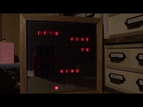
When everything works fine, the bottom right point should blink in red (approx. 20x) and then stay on continuously.
If the bottom LED doesn't shine, check your stripe and electronics connections!
The bottom right LED is the last in the chain, so if its blinking everything is fine so far.
What the heck ...
The clock tries to connect to a Wifi accesspoint, but we haven' let the cat out of the bag to which to connect.
The red LED indicates, that there is no connection to any wireless network possible and it is up to you to connect your mobile or whatsoever via Wifi to the clock's accesspoint called word_clock.
When connected, open a webbrowser and enter 192.168.4.1 (de facto standard address for such things).
The credentials page (see picture) displays all Wifi accesspoints within reach.
Select your accesspoint, enter password and click OK. The clock reboots.
By the way, in the final software the password is masked :-)
Only English text mask?
- Adjust ee_write_string(120, "de"); to ... "en" before the first compiling
otherwise the first program start initializes the EEPROM to German Language. - Put the German text mask on - if you understand German words
- The serial moitor will display the IP address as well. Open this in a browser and set to English (see below).
The web interface speaks English in all language settings.
After the first program start the EEPROM is initialized to German Language. The serial moitor will display the IP address as well.
Are we happy?
In case you've entered the correct credentials, you'll see the bottom right LED blinking again (approx. 10x) during WLAN connection. If connection was possible, the clock will display the IP address in words eg. (one nine two [pause] one six eight [pause] zero [pause] one two three
The first 2 numbers (192 and 168) are mostly the same at home, the last two numbers depend on your router since I've not hard coded the IP addresses.
Reconnect your computer to your home WLAN and enter the clock's address in your webbrowser.
If it was too fast simply reboot the clock.
Now, since we are comming via your home WLAN, the browser displays your clock's configuration page (see picture). Here we can change the color, set summer / winter time (auto for central european DST) as well as summer / winter offset hours to europe.pool.ntp.org standard time.
And last, but important: set the language appropriate to your chosen text mask. The German text mask can be used for north/west and south/east (fünfzehn nach acht / viertel neun)
Are you still here?
Congratulations! There is only one more thing to do: mount the marvel into a housing. I've used IKEA Ribba, because it's perfect fitting. IKEA kicked their 23x23cm / 9x9" Ribba in black and white - the successor is acacie.
Nevertheless, this looks much more better in a living room, I am going to replace all my black Ribbas to acacie.
Home Sweet Home, Put It Into Ribba
What we do in this step
- Making a home for the clock
- Mount the clock
What we need in this step
- The two boards
- IKEA Ribba
- 25x25cm mirror foil (maybe 2 of them, see below)
- Some snippets of wood or cardboard to fix
Tasks in this step
- Stick the mirror foil on Ribba's acrylic screen
- Mount everything
Let's go for the last activity.
There are several solutions for a front face imaginable.
- No front cover - ugly
- White paper - boring
- Mirror foil - Awesome!
Stick the text mask on the separator board - if not already done.
Stick together light separator and "mainboard" using some snippets of double sided foam tape. You will need two layers of foam tape to get enough distance (2mm) between the boards. It depends on the thickness of your tape.
Take the mirror foil, remove the protection cover and stick it on the acrylic (see Hints). Put the acrylic and the mounted boards into Ribba. Fix it with some snippets of cardboard or wood or whatever you want. Maybe glue it, but this is ultimate and not neccessary. Fix the USB cable to make a pull relief.
Close the back panel of Ribba.
Voila!
Hints
- Removing the mirror foil protection cover can be really easy using a scotch tape. Stick the tape on one edge of the foil an gently lift it.
- Sticking a foil on acrylic can be simplified by sprinkling some water with a drop of dish-liquid mixed on the acrylic first. Smoothly bring out the air bubbles and water with a credit card or dough scraper.
- If the mirror foil is too transparent and the text mask shines through, add one more layer of mirror foil
- I've fixed the USB cable with some wood snippets and I'm using magnetic USB cables to avoid tractive force to the USB contact. The USB breakout is not very reliable.
What's left behind?
The software? See next step, please.
The Software


How does it work?
My approach to coding a wordclock was consciously straightforward. Not compressed and not optimized. This will encourage you to read, understand and to customize whatever you want.
There are some sequences worth to be mentioned.
- Configuration stored in EEPROM
- Establish an accesspoint and shut it down after a given time
- Periodical calls 1/sec, 1/min, 1/hour without delay()
- Use NTP time
- Calculate summer / winter time (here: Central Europe)
- Use NeoPixel stripes
- Display IP address at startup
- Webinterfaces for AP and station mode (and determine by where we come from and what to do)
- Configurate color, time offset and language via webinterface
Here are some details:
The EEPROM stores in address 0 a magic word to detect the first start after the first flash. This avoids unexpected behaviour. GetConfiguration()
There are 2 functions to write and read strings to EEPROM. ee_write_string and ee_read_string
Summer/winter time calculation is made by setting time to the last day of summer month, get the dayofweek number, calculate the last Sunday and make a comparable value out of it. The same for end of summertime. Each minute the actual time is compared to the limits and we know whether we are in summer or not.
once_per_second() checks Wifi connection and if lost, try a reconnection
it also handles the webserver and an accesspoint shutdown timer
once_per_minute() reads configuration, calculates summer/winter mix it with NTP time and displays the time.
Setting last_minute to 99 will force execution of once_per_minute() immediately (eg. webinterface color change)
NeoPixel: NeoPixelBus uses ESP GPI02. This is D4 on D1 mini. Pixelpin is ignored by the library. ahead of a display change all LEDS are set to black, new LEDs are set to color and only now the strip.Show() is called. This avoids flickering.
All the other code should be self-explanatory - if you are familiar with coding at all (if not, use it and don't care)
At the Very End
Have enough guts to make such a nice gadget for your living room or as birthday gifts as I do.
Everybody with basic maker skills can do it! You don't beleive? Please watch the videos and you'll be convinced.
Thanks for reading this Instructable and please give me a feedback when you made your own Wordclock. I'm really curious about it.