Wood Thicknesser Vacuum Adapter With Fusion 360
by Kevr102 in Workshop > 3D Printing
1480 Views, 11 Favorites, 0 Comments
Wood Thicknesser Vacuum Adapter With Fusion 360
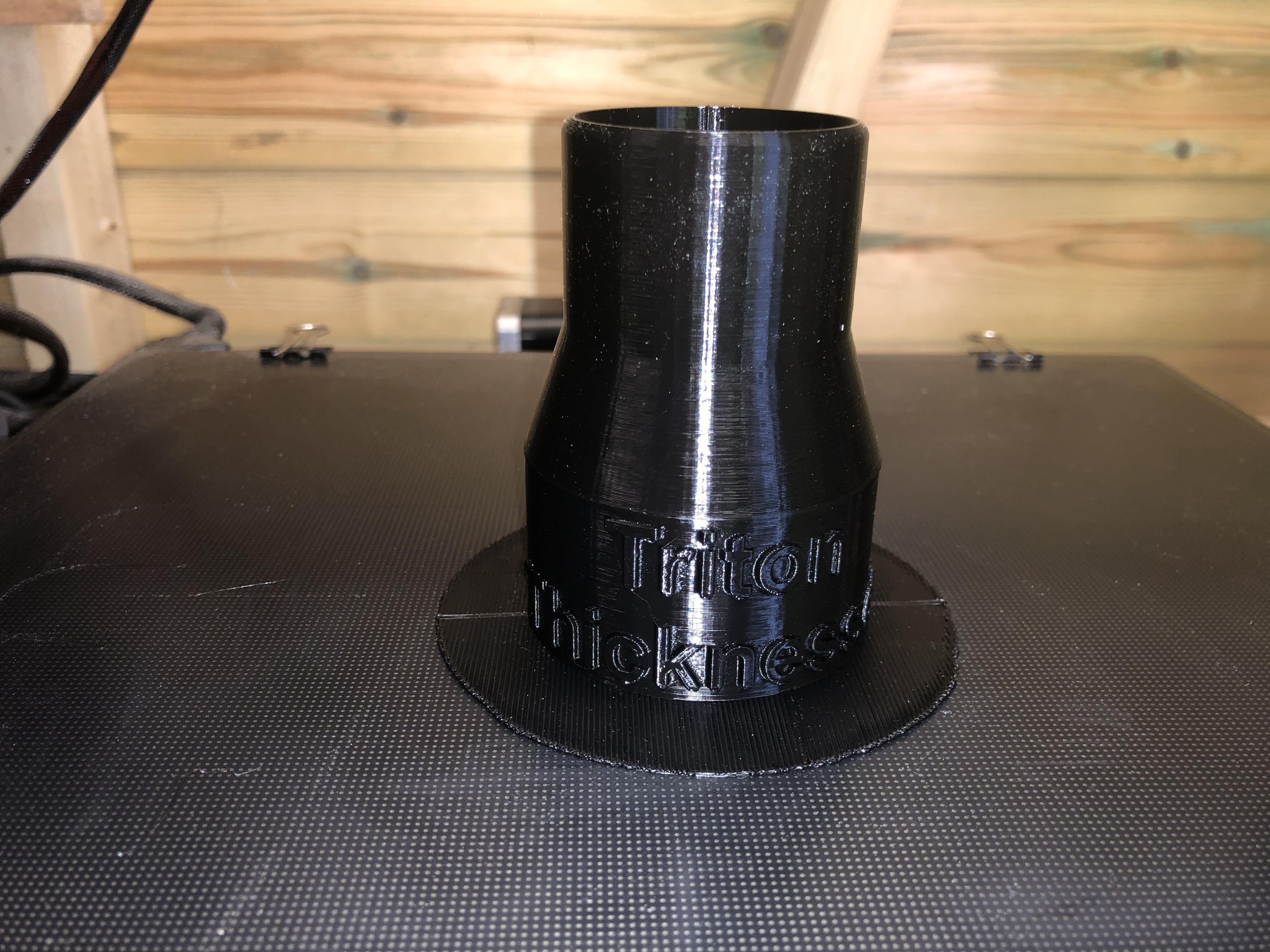
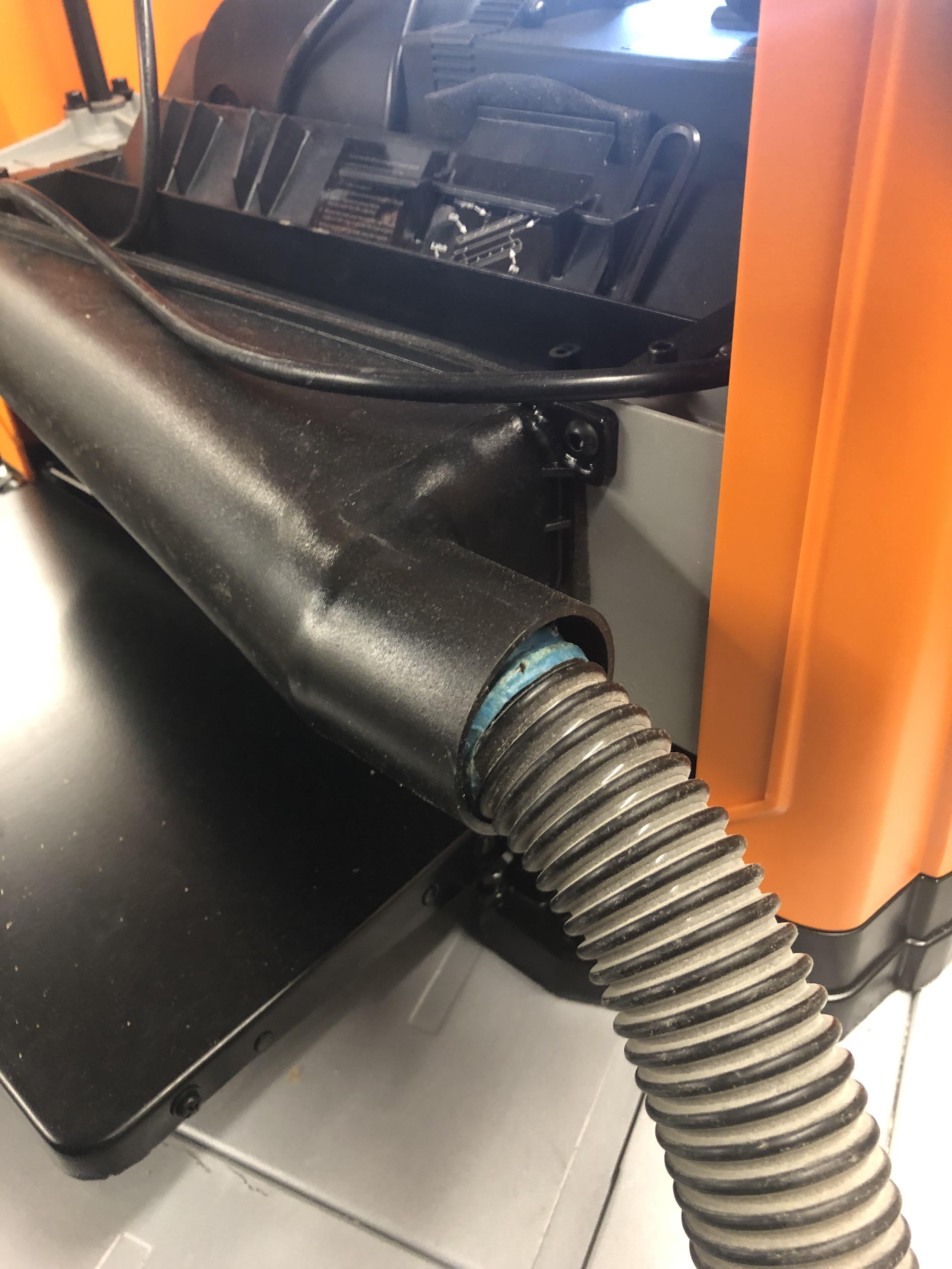
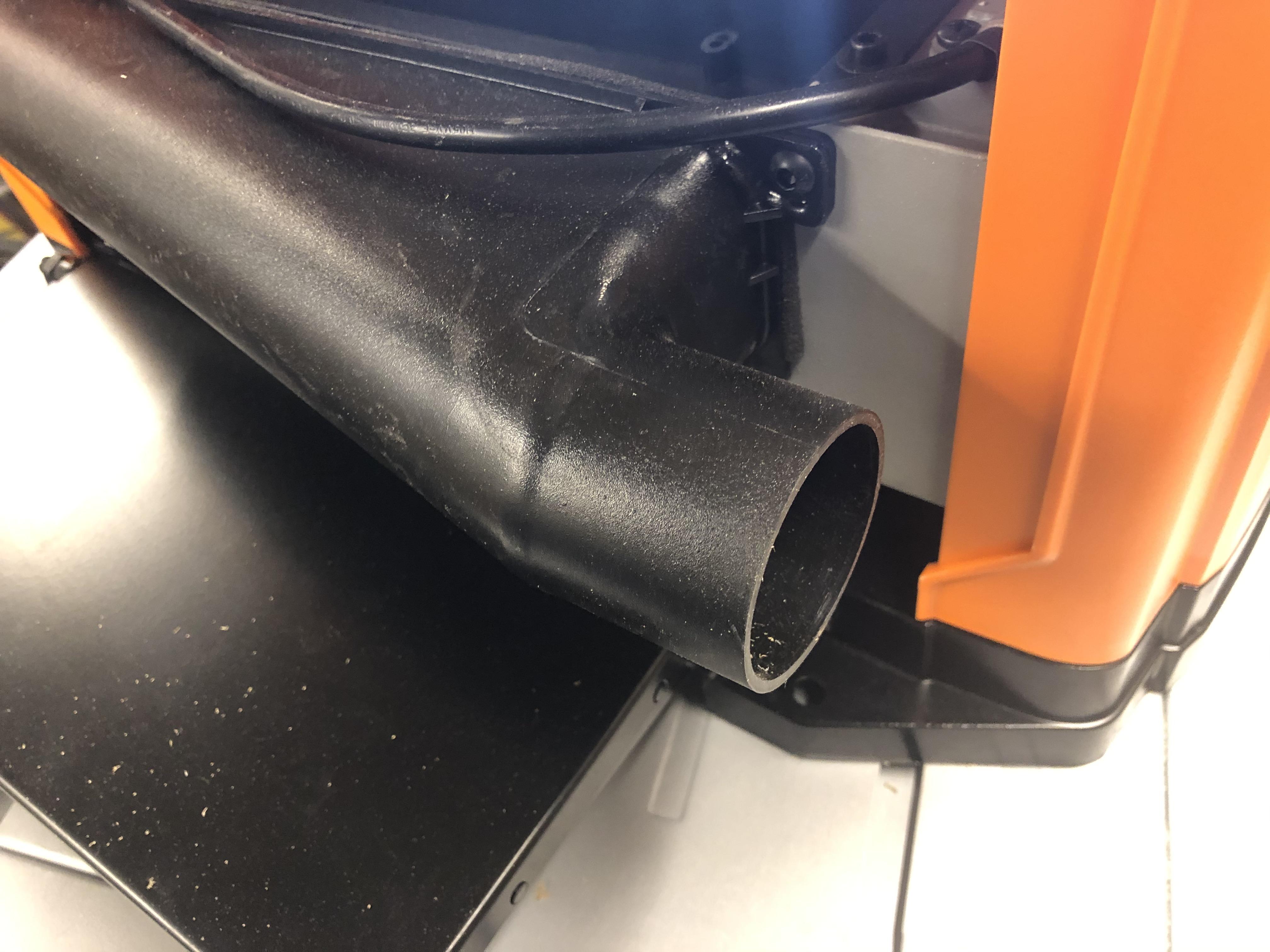
I've just nicely sourced a wood thicknesser to save me hours of sanding re-cycled pallet wood etc.
True to form, every Vacuum adapter I have doesn't fit it so I thought it would be a good idea to do an Instructable showing in detail how I make the Adapter using Fusion 360
In Fusion 360 we will be starting off with construction lines, Offset, Revolve, and i thought it might be a good idea to have a name on the Adapter, so for this we will be using Text and the Emboss functions.
On with the design:
Supplies
3D Printer
1.75 Black PLA Filament(Any colour will do)
Fusion 360 Sketch
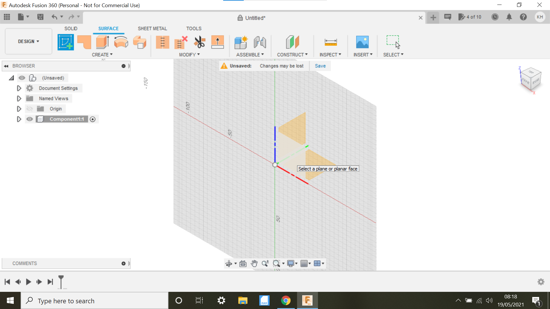
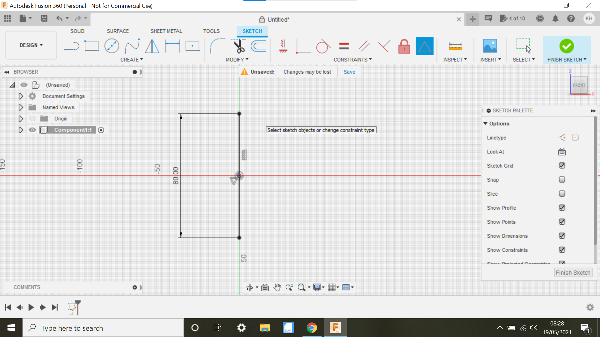
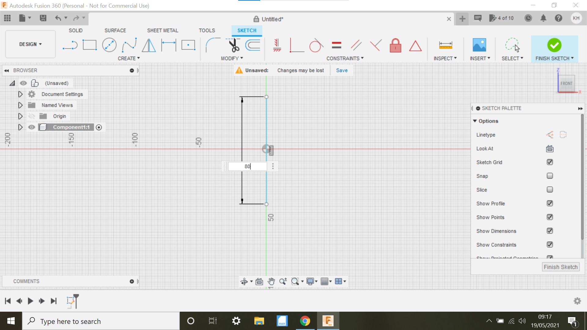
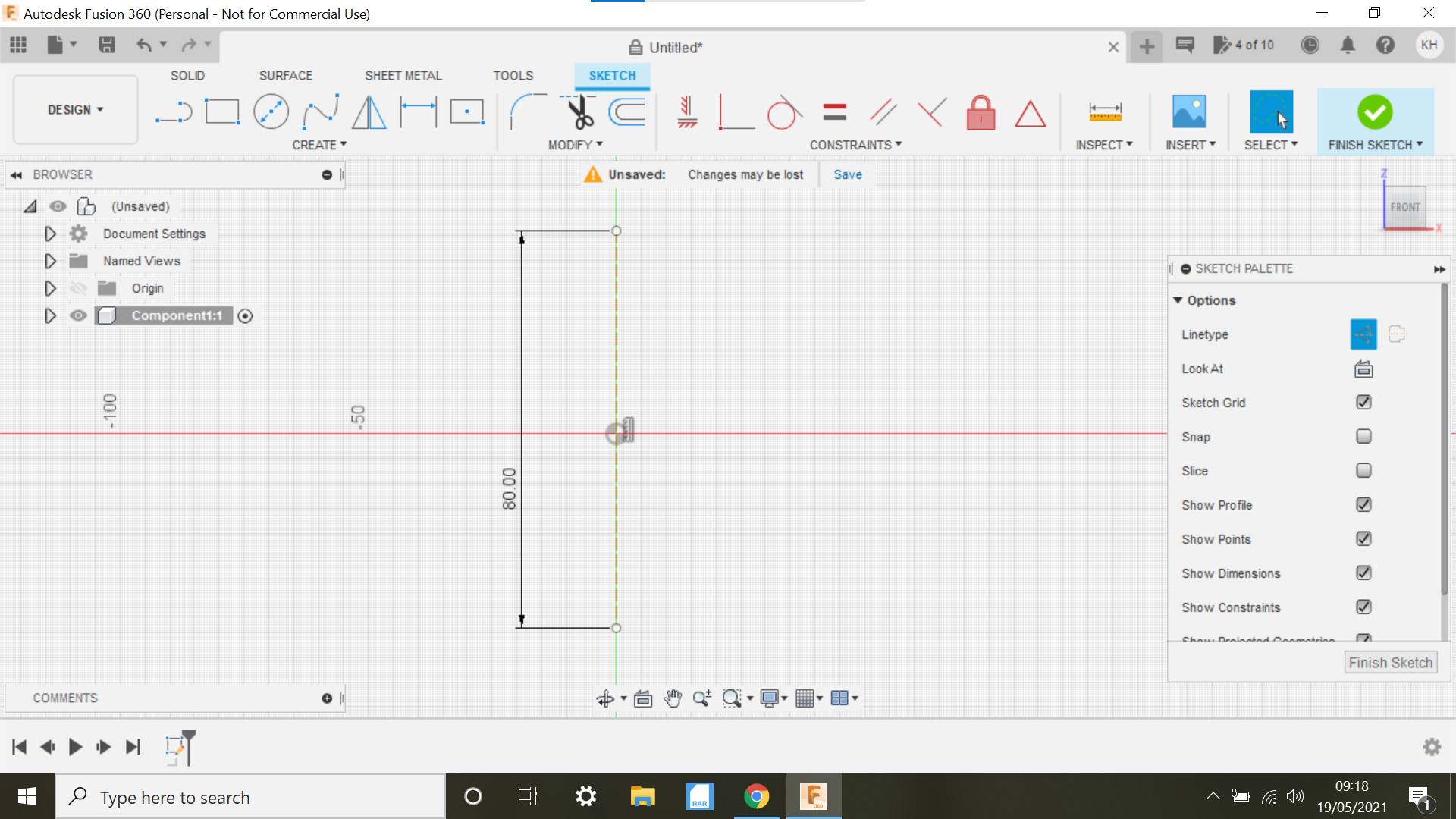
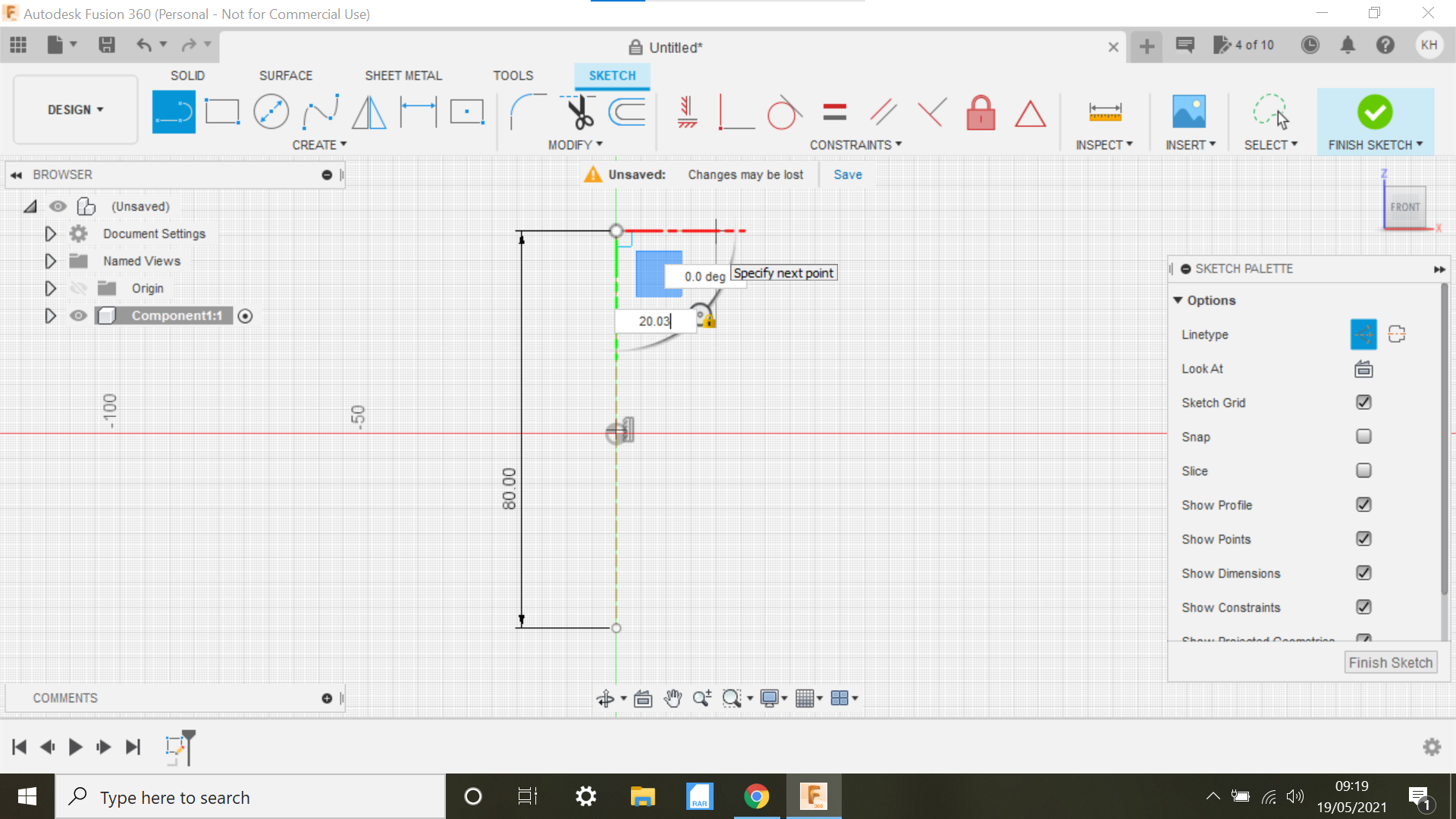
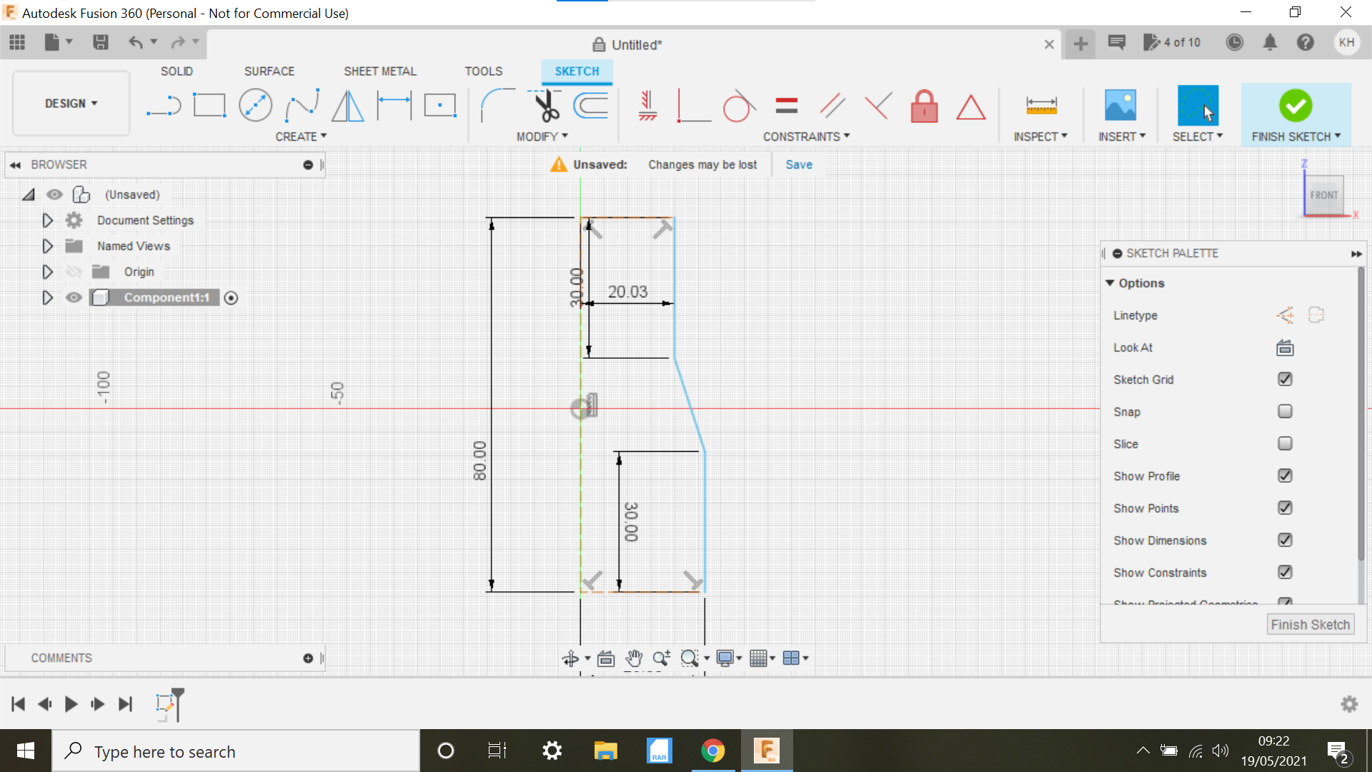
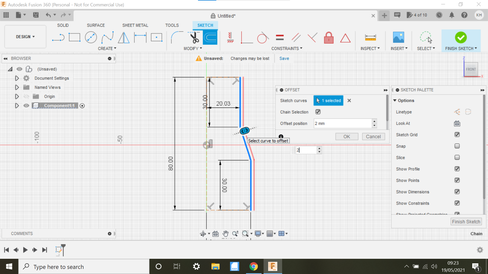
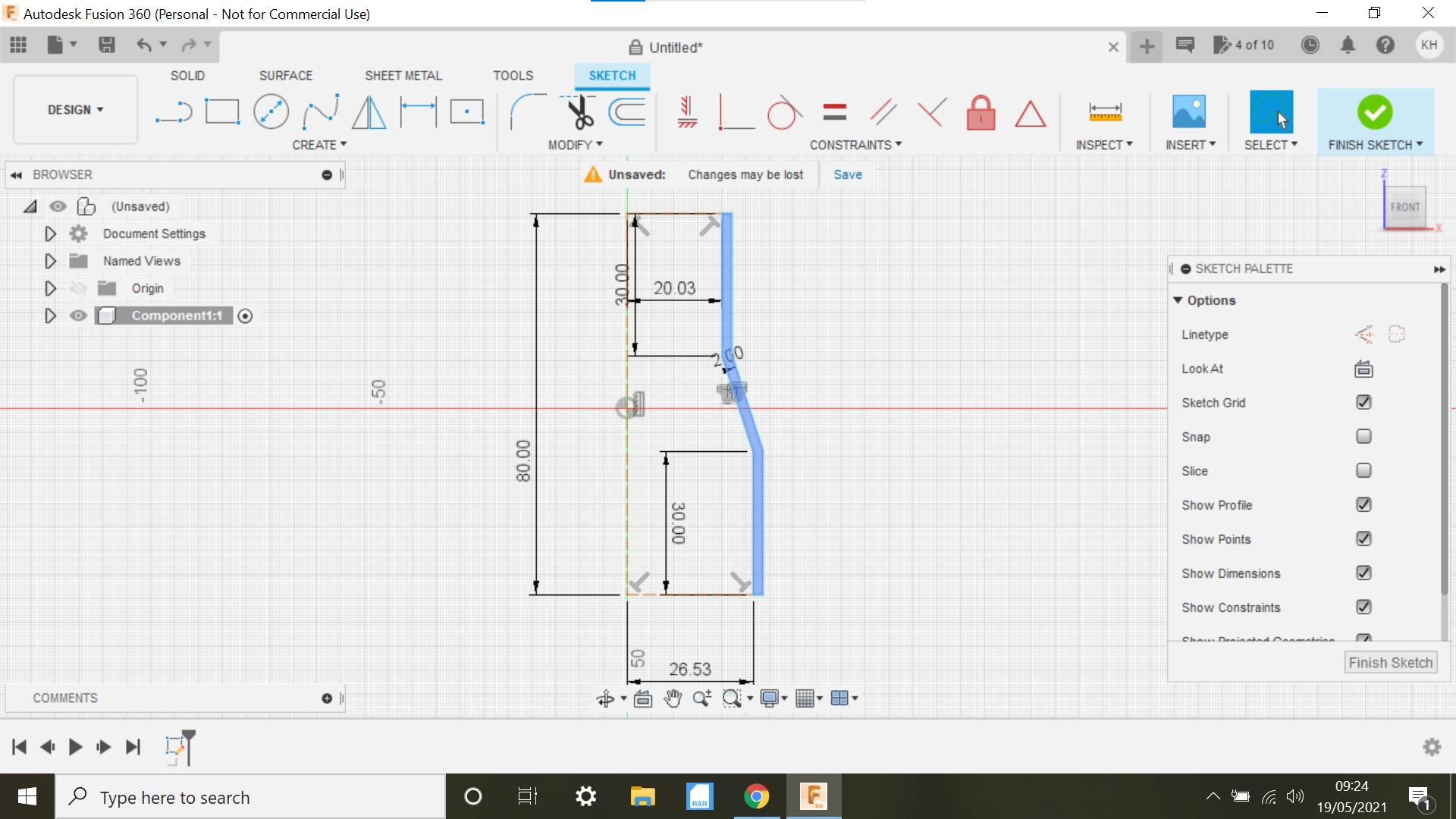
In this operation we are creating a sketch which we can then revolve to create the shape of the adapter.
To start the sketch we create a new component then select the front face and highlight, we then click on the line tab and create a line 80mm in length, select mid point and align the line to the centre, turn this line into a construction line.
The dimension of the Thicknesser outlet is 53mm and the vacuum tube diameter is 40mm.
Create another construction line to the top of the first line at 20.03mm i want a snug fit and i may have to sand the inside of the adapter to fit correctly at both ends.
Now create another construction line at the bottom of the first line at 26.57mm.
From the top construction line create a solid line at 30mm same with the bottom line, then connect the 2 lines, this now gives us a basic outline, click the offset tab and offset the solid line outwards to 2mm
At this moment in time the sketch is not closed, connect the lines at the top and bottom to achieve this.
The sketch is now complete.
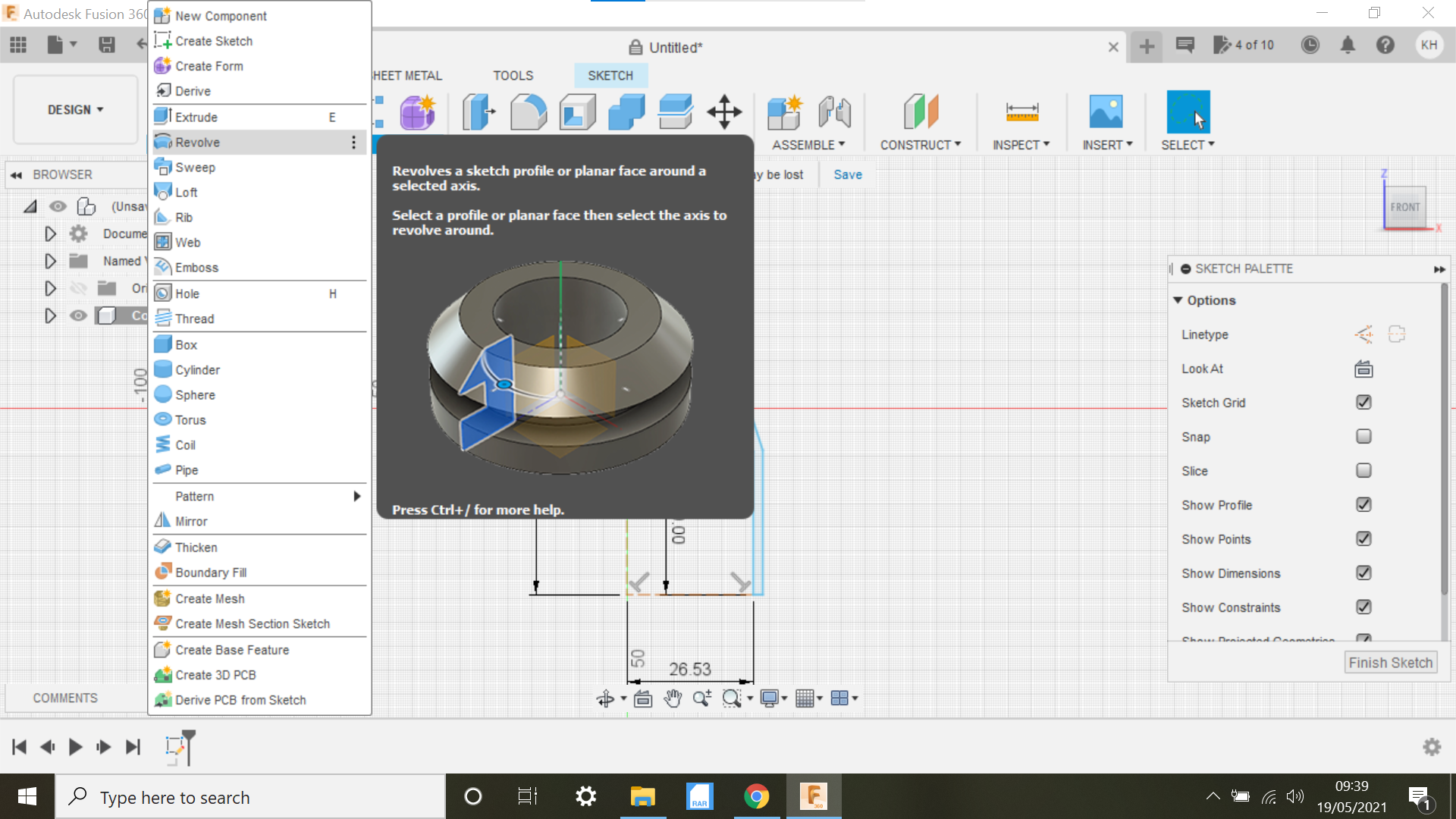
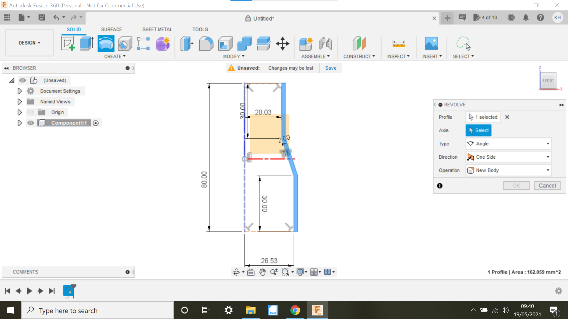
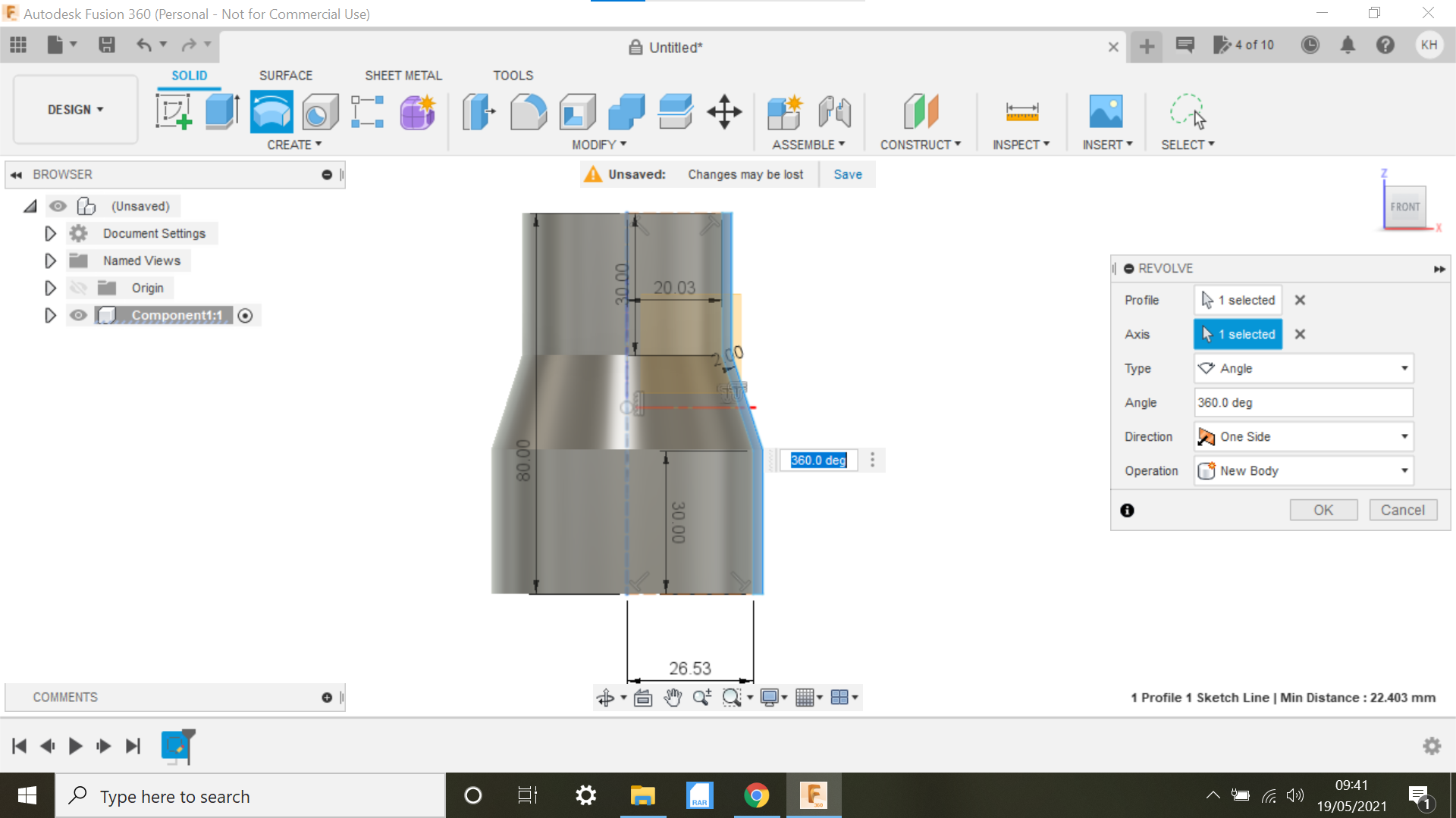
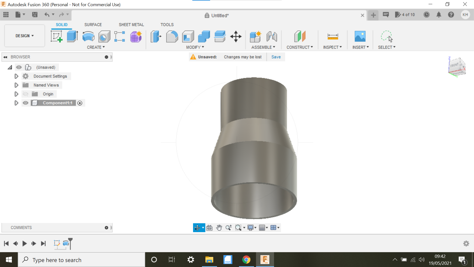
In this section we can now use the Revolve function to create the adapter.
Select the Revolve Tab, we have to go into Solid to find Revolve, highlight the sketch we created, it will turn blue,
clicking on the Axis tab we can now click on the original construction line and quick as a flash we now have the adapter.
Lets add some text to the adapter.
Creating Text on the Adapter and Using the Emboss Function to Wrap the Text
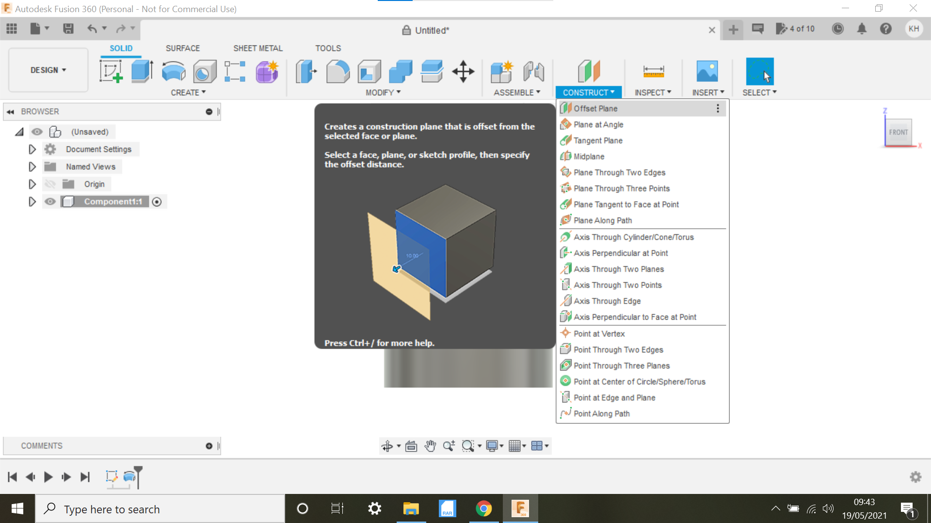
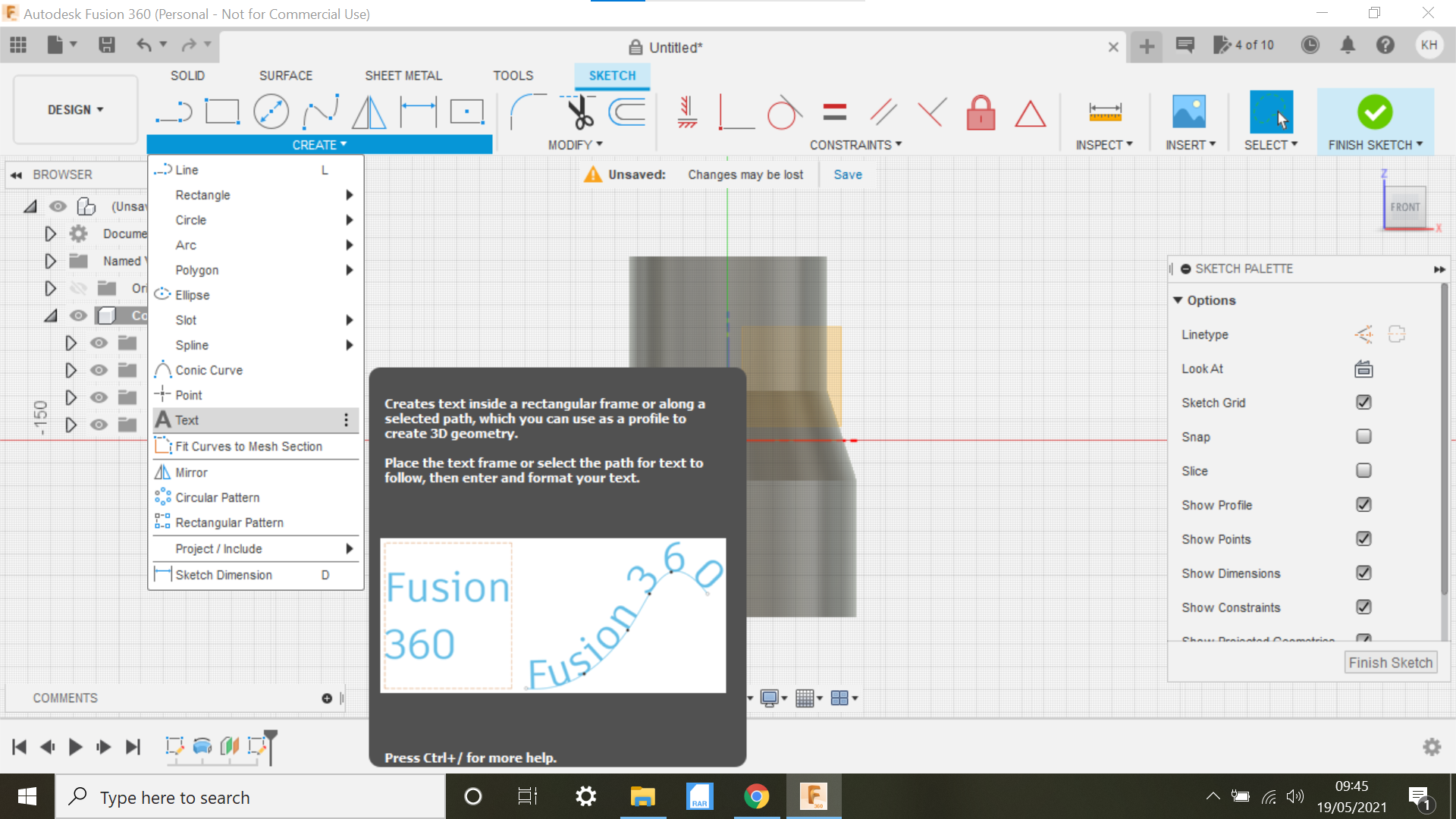
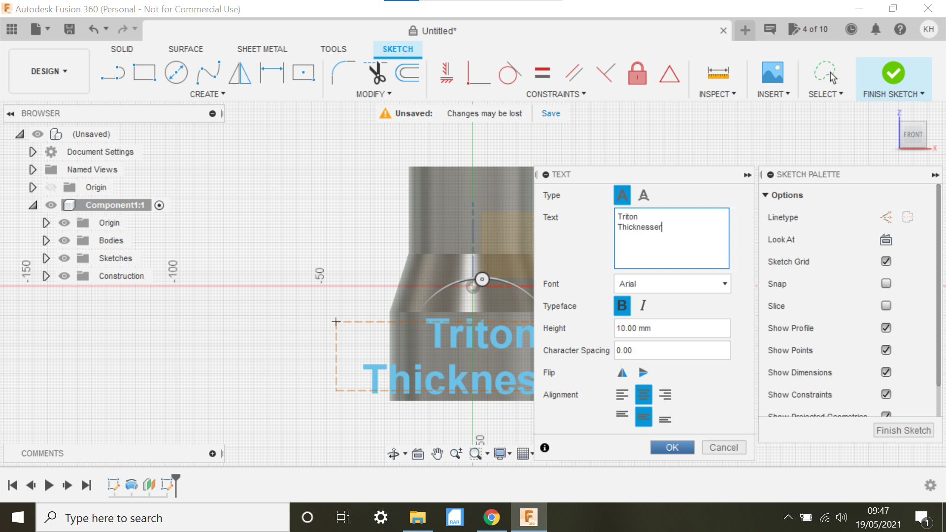
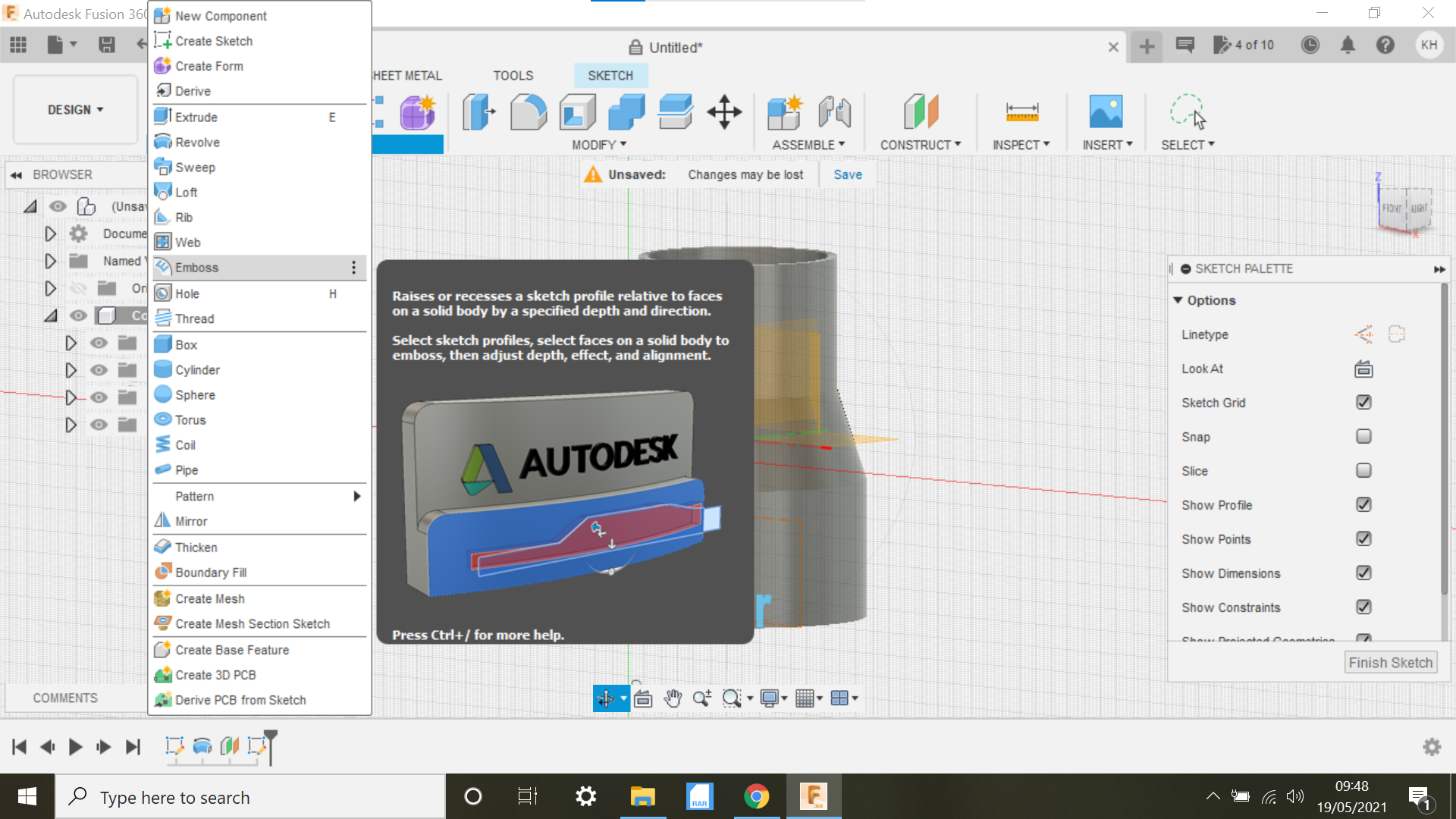
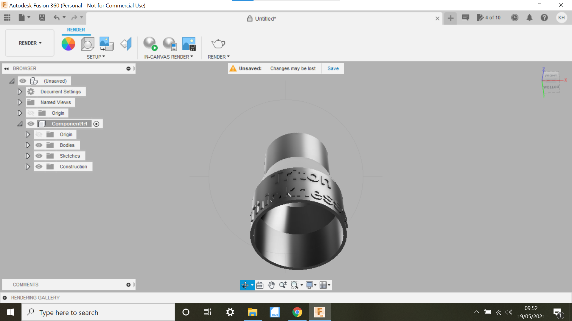
We need to create an offset plane, highlight the Middle plain and move if forward say 35mm then create new sketch and click on the offset plane now select Text.
Drag a box around where we want the text, and in the text box, input the text, select the size, bold and centralize from here, click ok.
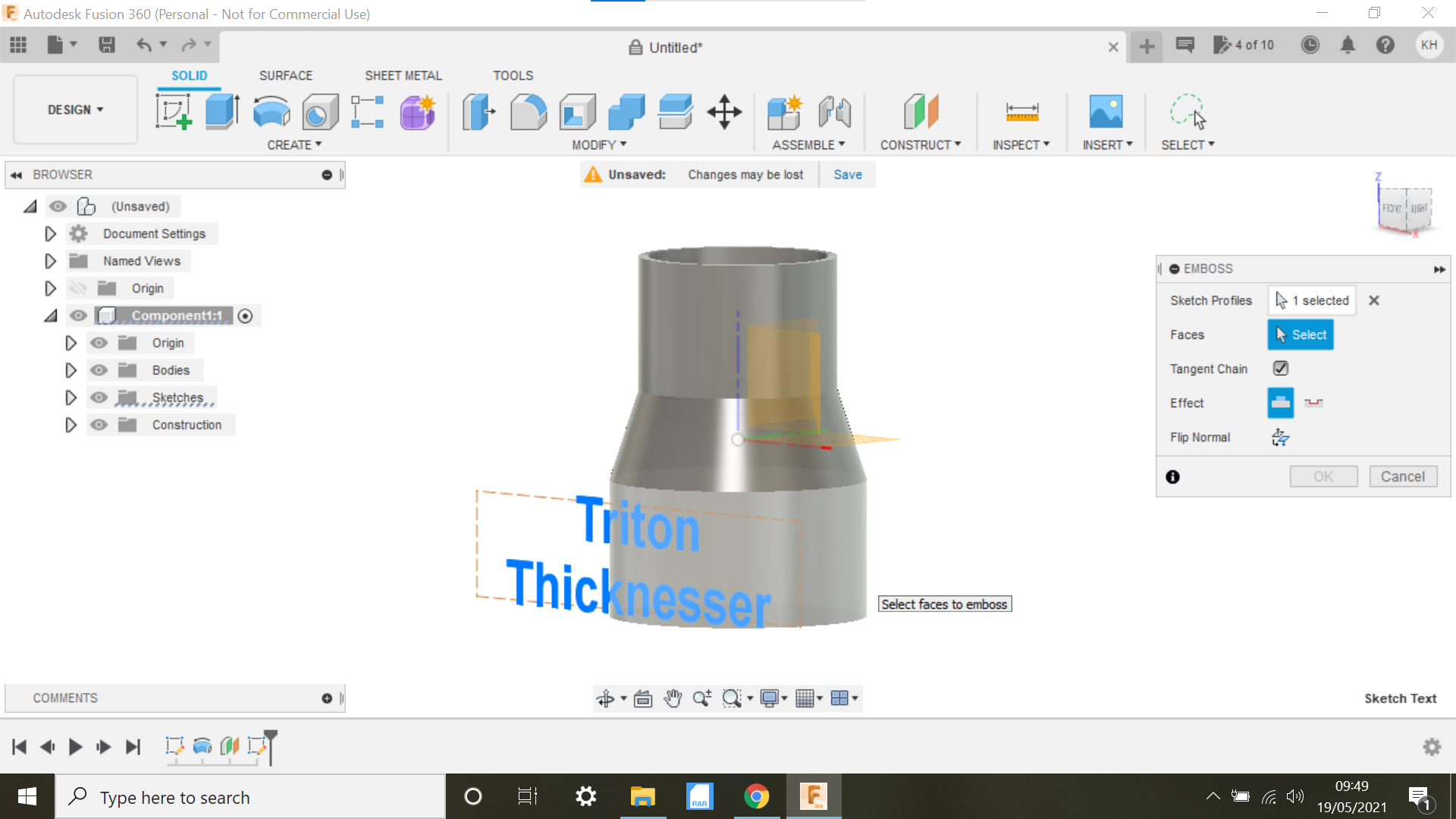
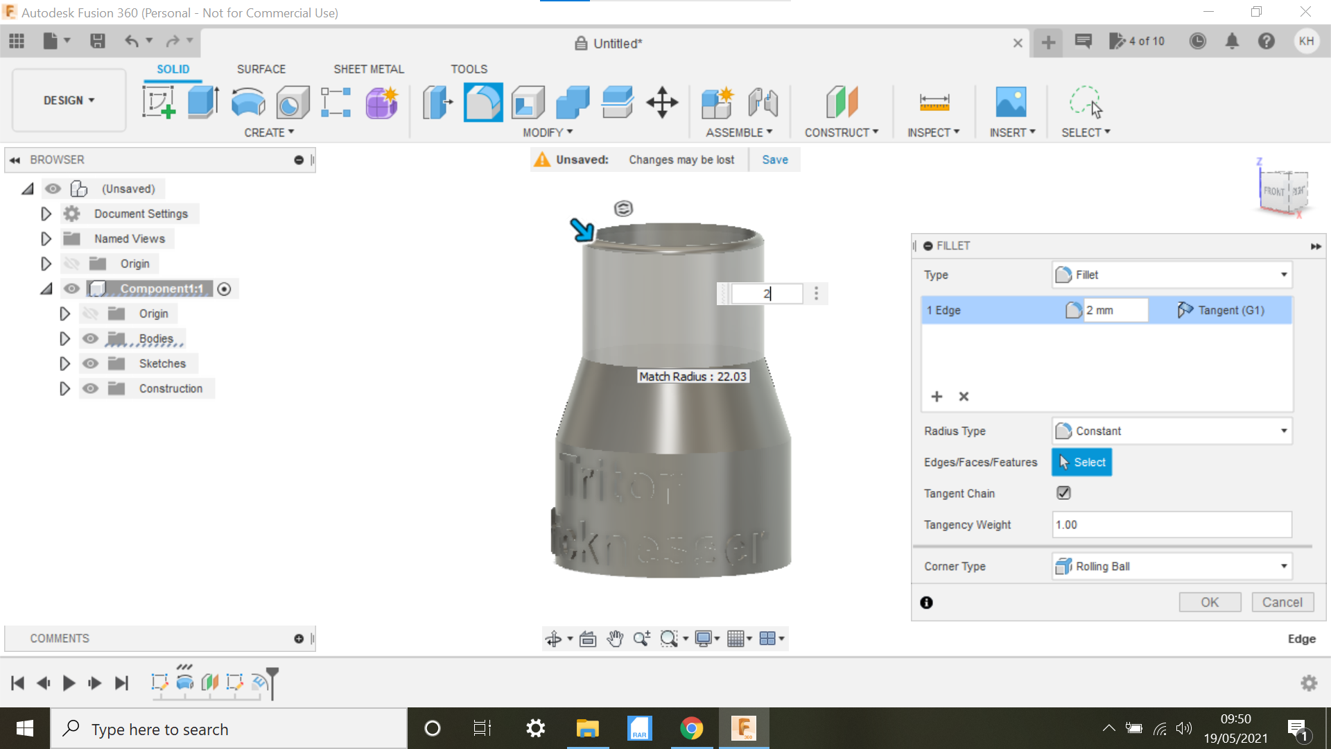
From here we need to select the solid tab again and click on Emboss, Highlight the Text and the click on face, the text will now be Embossed on the adapter, you can select the depth of the text and its possible to deboss the text if you prefer to do this, ensure the wall of whatever you are making is thick enough to accept the text.
The End
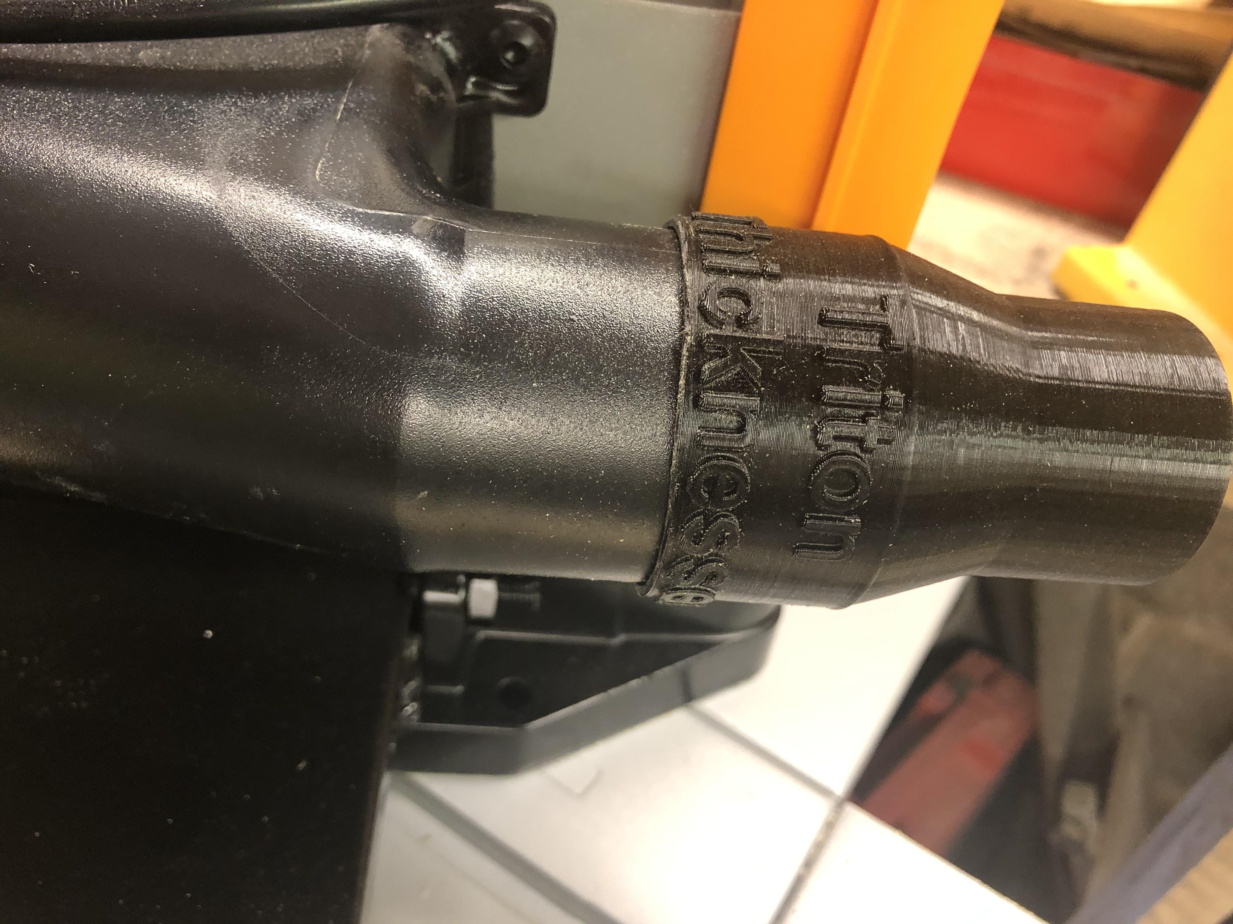
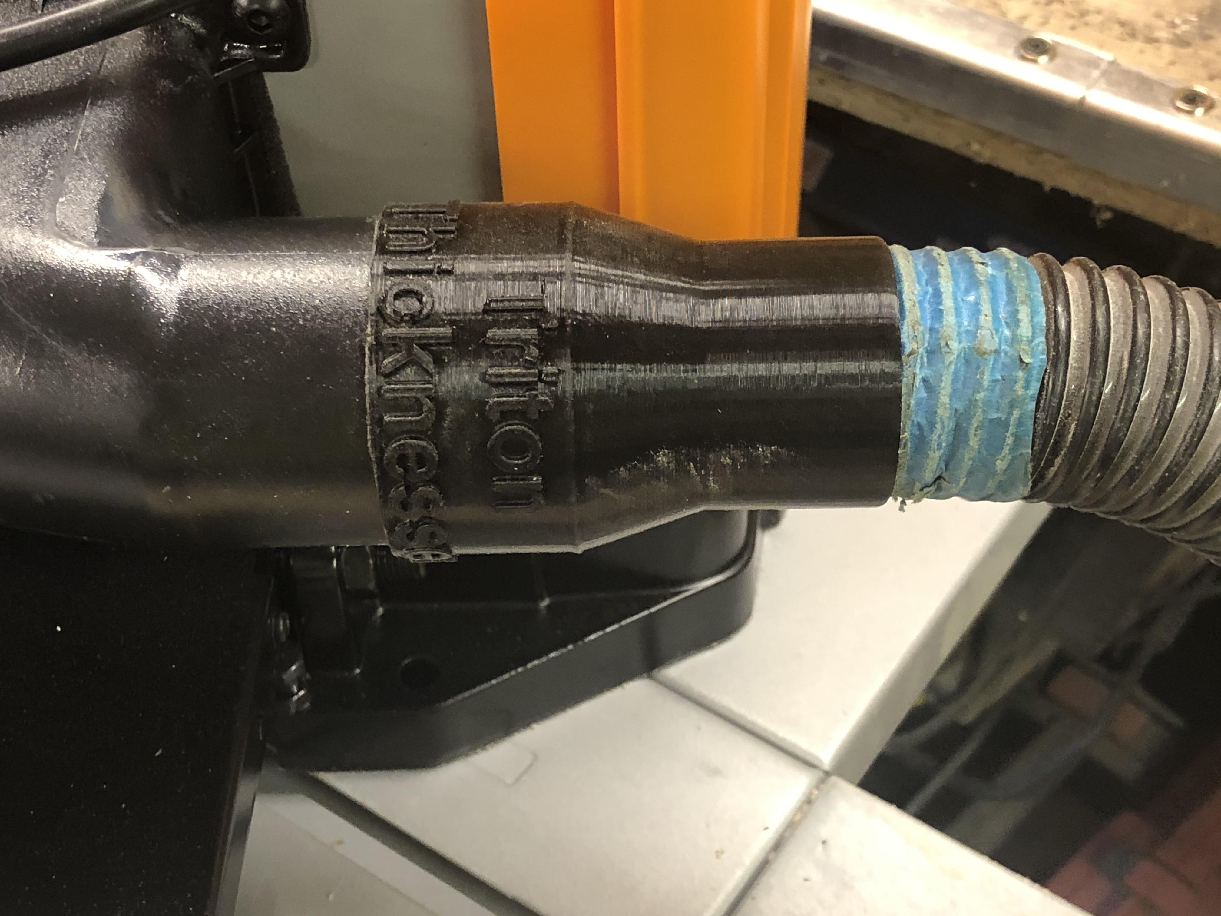
There you have it, a fairly simple process of creating an adapter that fits perfectly.
Thanks for looking and see you in the next one.