Wood Incrustation With Fusion 360 and CNC
642 Views, 2 Favorites, 0 Comments
Wood Incrustation With Fusion 360 and CNC
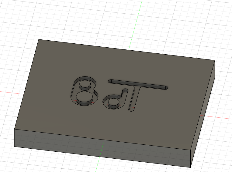
Well you need ...
A CNC ...
and some pieces of wood. 2 different species. I'll be using Oak and Azobe.
And a CNC bit that will work on the wood you selected. Azobe if very hard so I need a very hard bit.
And of course Autodesk Fusion 360 (free for hobbyists)
Fusion 360 Make a Sketch of Your Incrustation
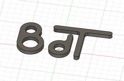
First thing first, select a tool you'll be using to machine the thing. Should be a flat end mill. Select your diameter. This diameter will be crucial in the design. The mill must have enough space to pass in all locations. Design all considering a slightly bigger diameter to allow clearance to be added afterward. I'll be using a classin 1/8 inch tool but all is designed for 4 mm.
First thing is to do a sketch in fusion that will hold your incrustations. See the video.
Important things :
- all passages should be large enough for the mill (+clearnce)
- everything shoud be rounded so that the tool can mill inside corners. So in my design all is rounded with at least 2 mm radius.
Have fun.
You'll find many videos on the net on how to use Fusion for creating sketeches. I just give you a preview here.
-
Downloads
Fusion : Extrude the Incrustations
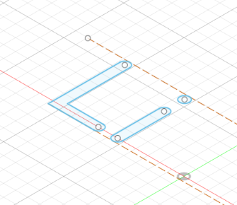
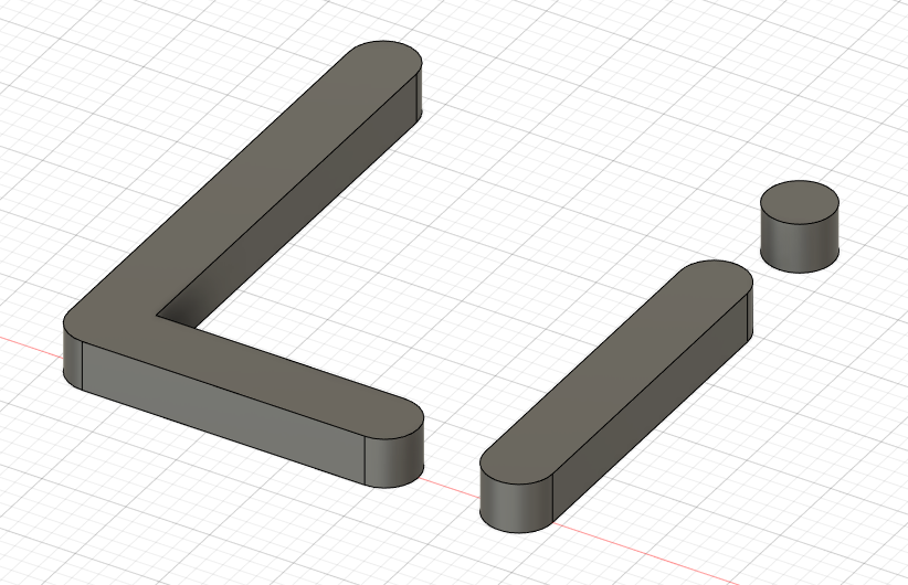
From the sketch I give some thickness to the incrustation with the extrude tool of Fusion 360
Downloads
Create the Base Component That Will Hold the Incrustations
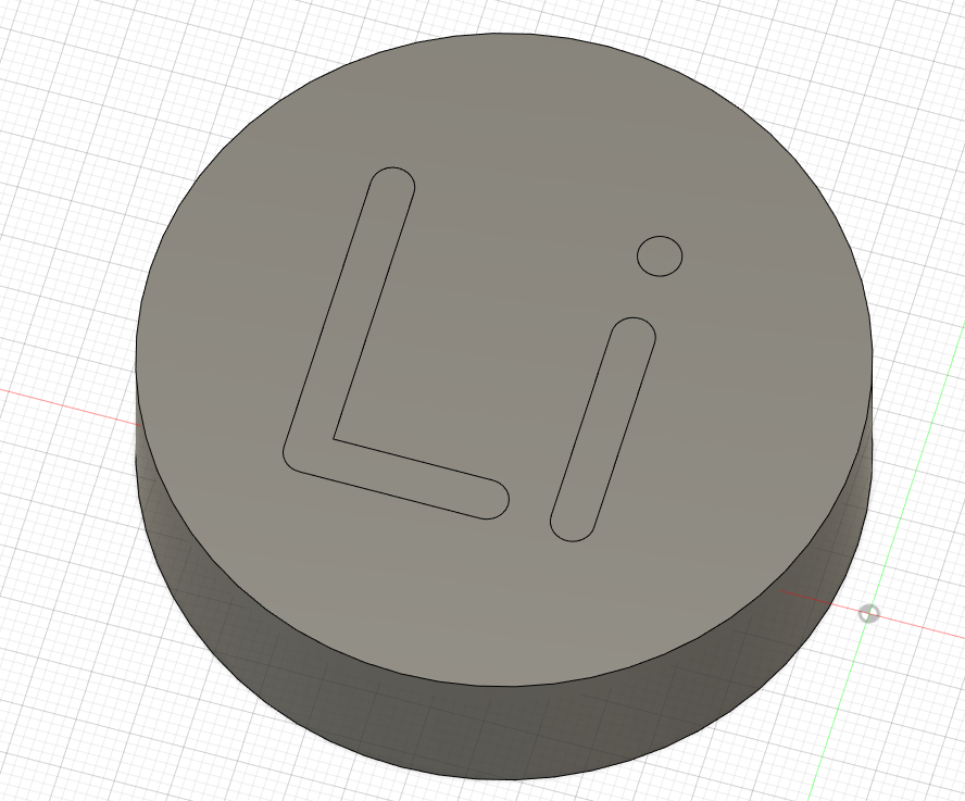
This step in fusion is a bit more tricky. Following steps :
- create a plane at the top of your incrustations
- create a sketch on that plane
- draw the extends of your base component in the sketch
- Extrude the compoenbase component
See the video...
Downloads
Combine Bodies to Cut Cavities While Keepin the Incrustations
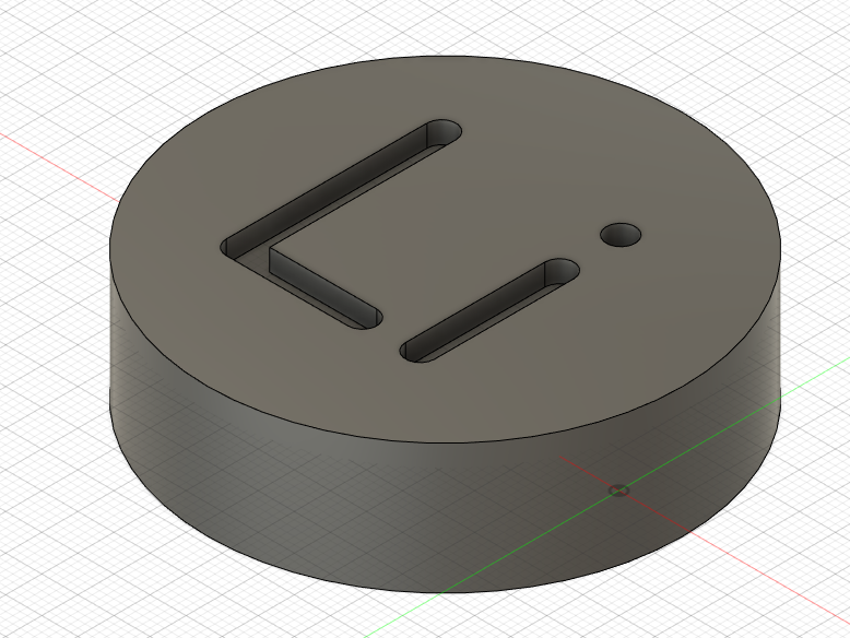
In this step we combine our bodies to cut cavities on the main part while keeping all bodies in place.
Downloads
Compute Cutting Parameters
Here we create a first setup for maching the main part.
Here are main parameters :
- I'll be maching that in a piece of oak. Let's say hard wood
- I'll be using 1/8 inch flat end mill of basic quality with 2 flutes
- spindle rotation speed on my CNC is limited to 8000 rpm
- feed rate on my CNC is limited to 2500 mm/minute
Here's all the theory :
https://static1.squarespace.com/static/59efc96d90b...
So for hard wood and 1/8 inch mill they recommand 18000 rpm. Too bad that will be 8000 rpm as the machine can't do more.
So they mention a chip load per leading edge between 0.003 an 0.005
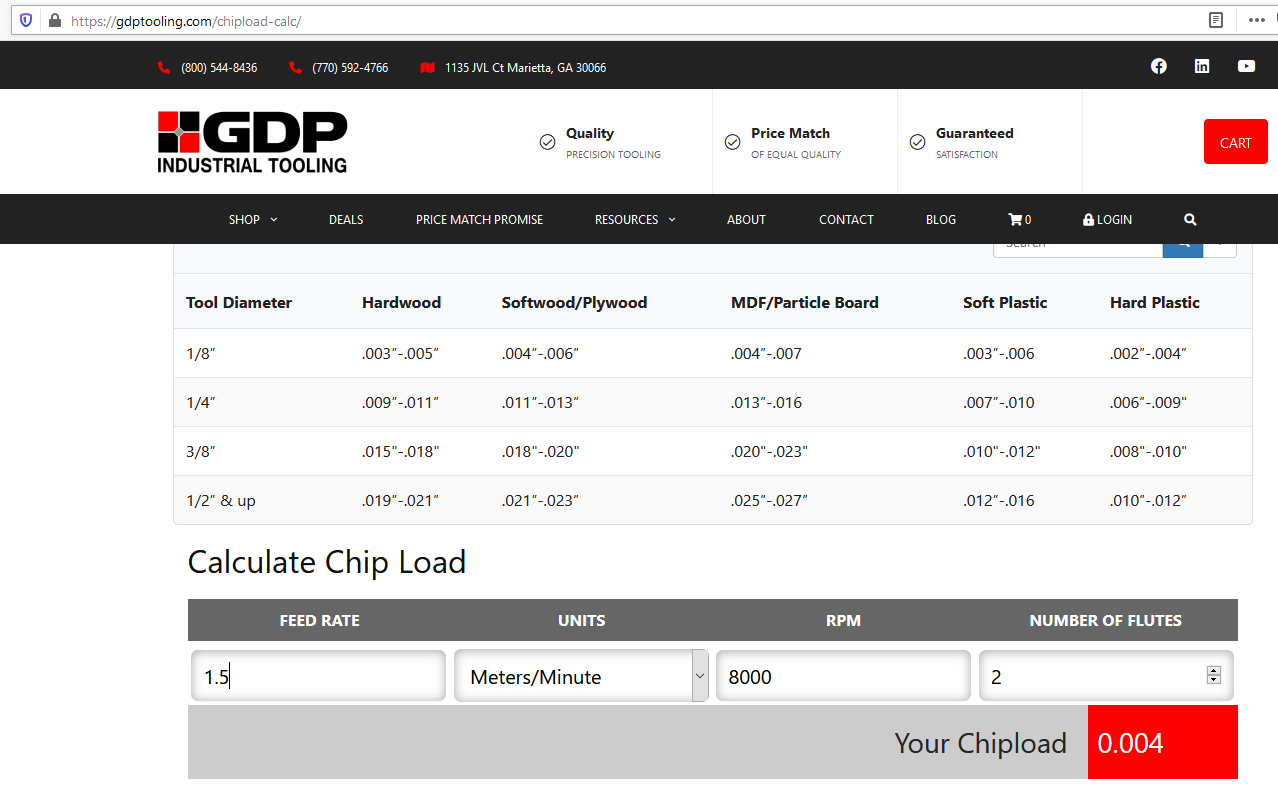
Let's take that to Chip load calculator :
https://gdptooling.com/chipload-calc/
I find out that with a feed rate of 1.5m/minutes that is 1500 mm/minute I get an average chip load of 0.004.
It your chipload is too low your tool will not have enough material to cut and you get a kind of powder. Your tool will heat, wood will become dark and finally the tool will lose cutting qualities and break.
If chipload is too high, the tool cannot remove enough materail for each pass and will break too.
The table show you can cut as much as the tool's diameter in depth. I'd start with less tahn that. My start point in 1 mm, maybe 1.5mm depth pet cut as it's no high quality tool. This also depends on spindle power that is limited to 200W on my machine.
So in the end here are the parameters :
- hard wood (oak, will be the same sor Azobe in the next setup)
- 1/8 end mill
- maximum spindle speed of 8000 rpm
- chipload 0.004
- feed rate 1500 mm/seconds
- passes of maximum 1mm
Note that with better CNC and tool I'd double spindle speed, feed rate and pass depth so machining time would be divided by 4.
Also note that shipload is really low for small diameter tools like this. Every time it's possible I use 6 mm mills that allow me tu use max feed rate and are confortable with passes of 1.5mm. less risk to break the tool and machining twice faster. Again with a faster and more powerful spindle and a CNC that support faster feed rates I coud improve machinig time by a factor of minimum 4.
Conclusion : if you don't have the budget for a professional CNC, machining takes (much) more time.
Setup the Machining Operations
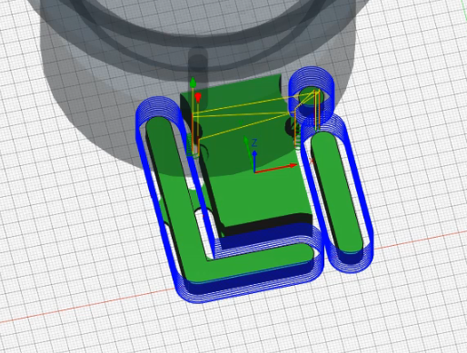
Here we prepare the machining operations in Fusion 360 and produce GCode files
See the videos
Produce !
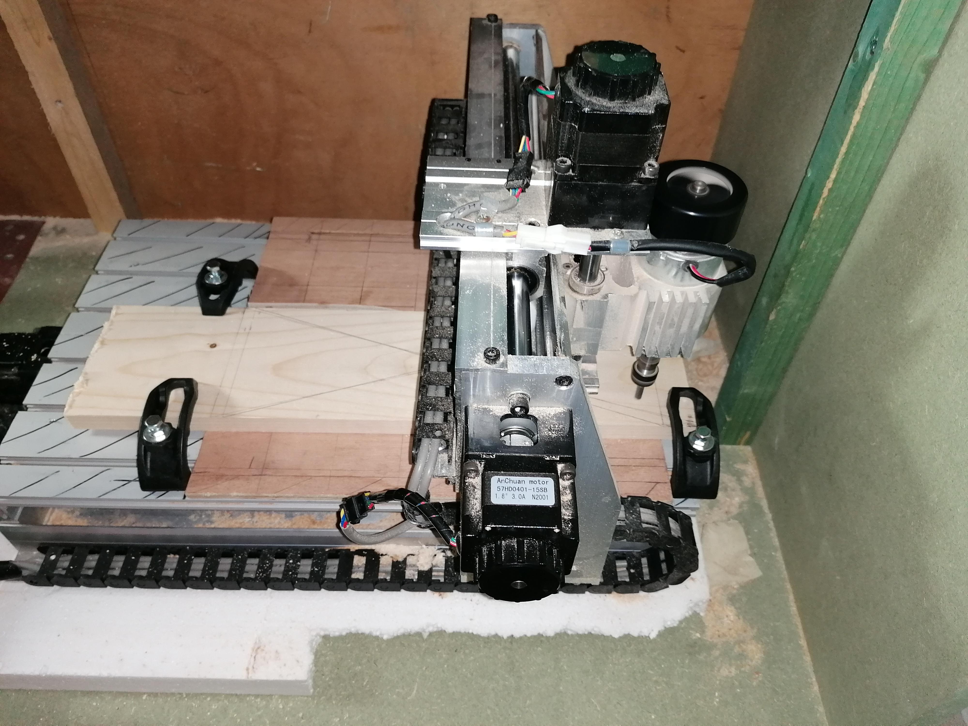
You've got your GCode ready.
Fasten your first stock on the bed of the CNC.
Check axis screw are fastend and tight
install the tool
if your machine does not have limit switches set home position well above with G28.1
Set zero on the top center of your stock and run.
Repeat for the other setup.
Assemble, glue, finish with sandpaper...