Wiring and Programming SMARS V1 (Etsy Version)
by smars_project in Circuits > Arduino
3271 Views, 8 Favorites, 0 Comments
Wiring and Programming SMARS V1 (Etsy Version)
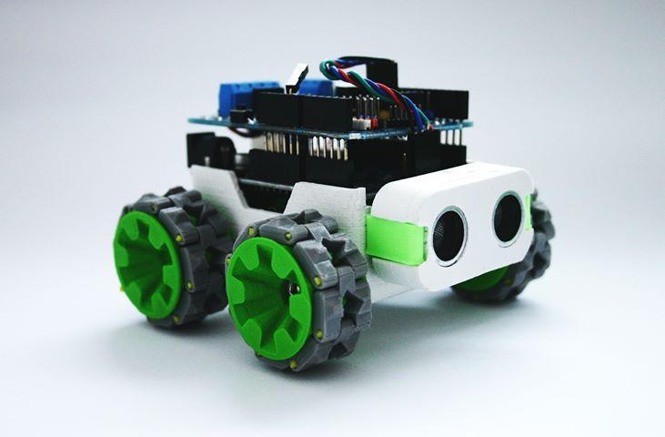
This guide explains how to wire up and upload code on the SMARS V1 with official electronics kit available on Etsy
Supplies
An already assembled SMARS ( assembling guide and .stl files available here : https://www.thingiverse.com/thing:2662828 )
SMARS Electronics kit https://etsy.me/3qxYLdx
HC-06 bluetooth module http://s.click.aliexpress.com/e/739DNs4
SMARS APP https://play.google.com/store/apps/details?id=com.bluino.smarsapp&hl=it&gl=US
Arduino IDE https://www.arduino.cc/en/software
Insulating tape
White A4 paper sheet
9V battery
Motors Wiring
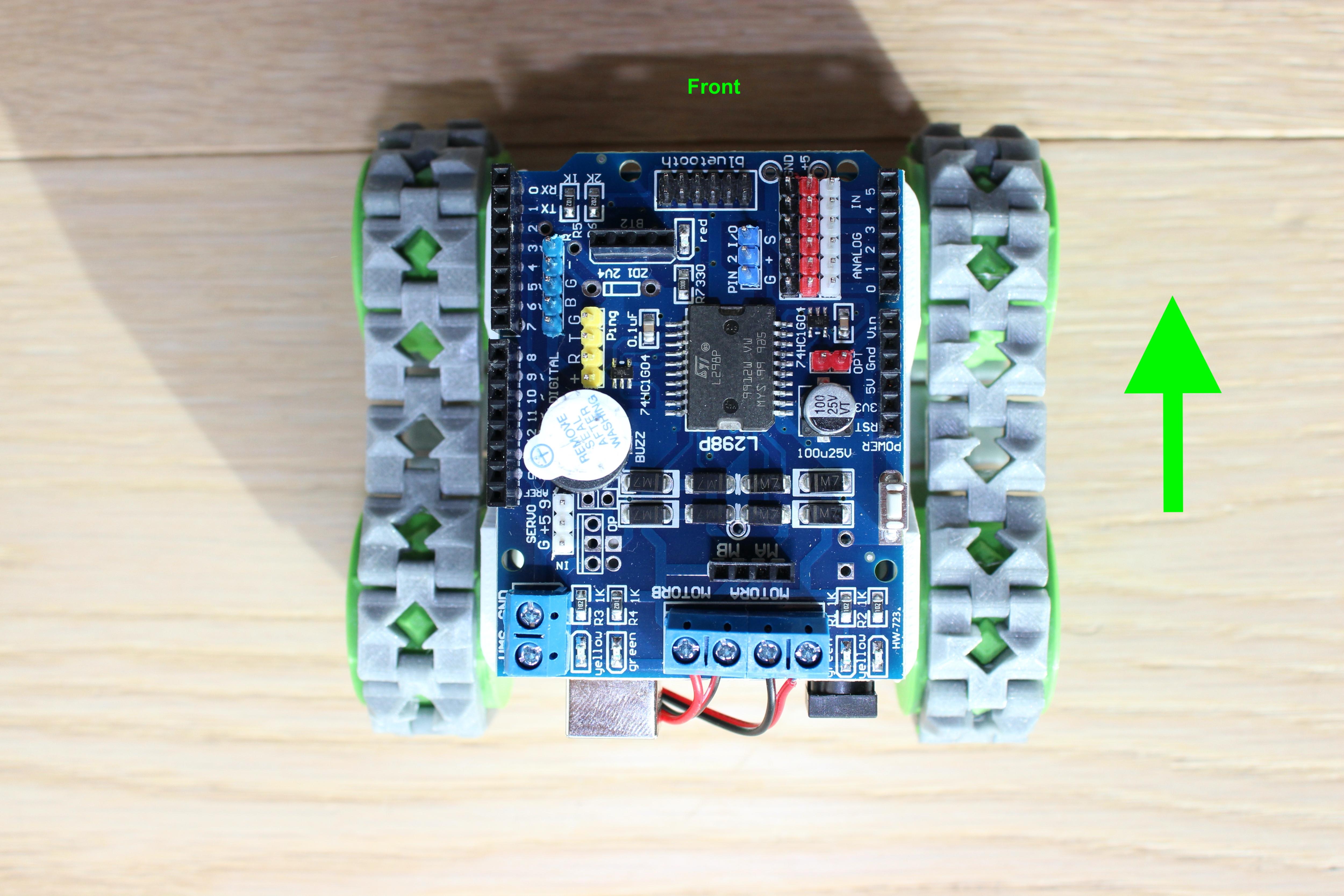
First step is connecting the motors as show in the pic.
The robot will move in the direction of the arrow, so be sure to connect left motor to "MOTOR B" port and right motor to "MOTOR A"port. Starting from left the connections must: L+,L-,R-,R+ (+= red, -= black).
Ultrasonic Sensor Wiring
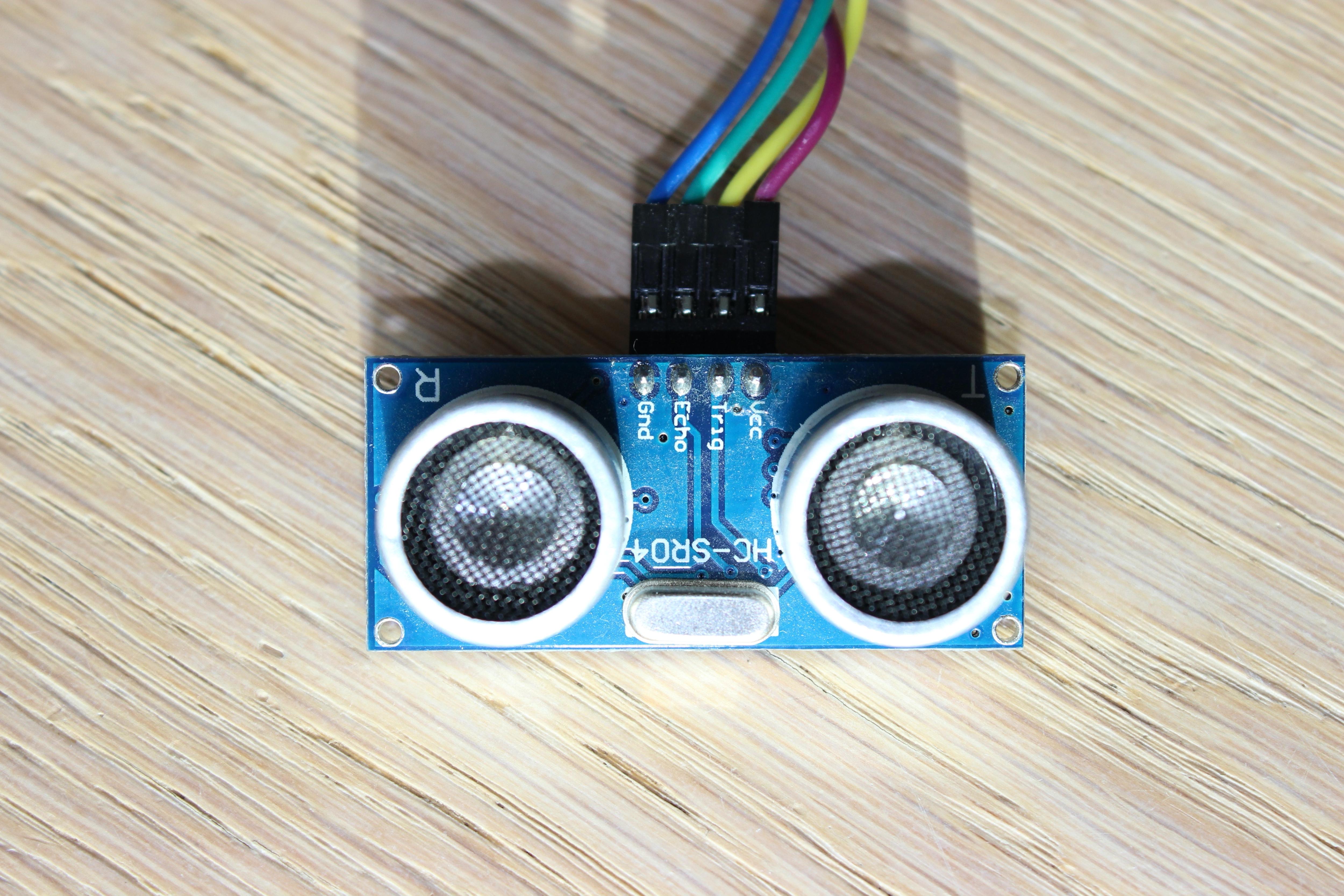
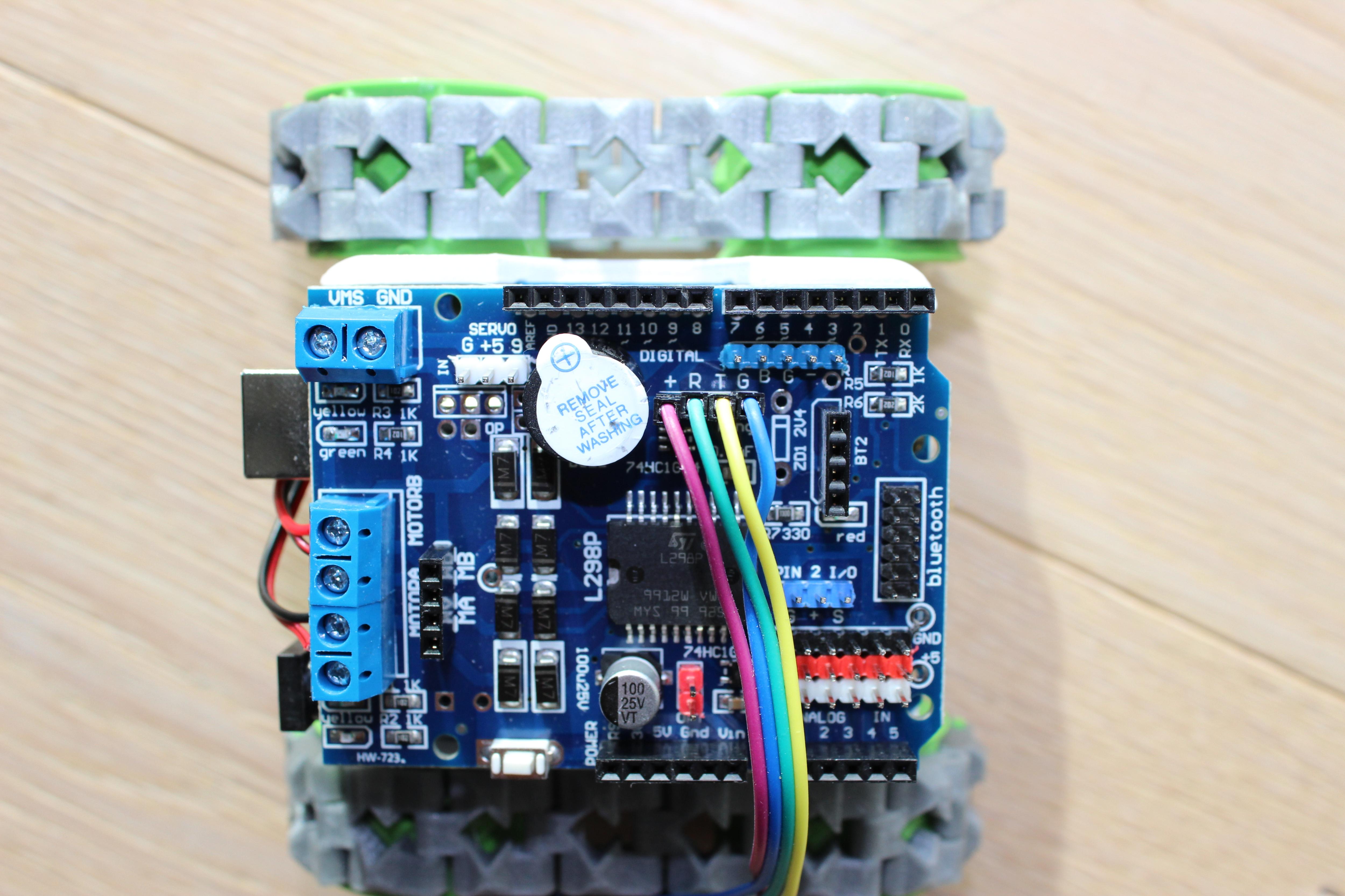
Second step is to connect the ultrasonic sensor to the Motor Shield. The sensor's pins must be connected to the shield in the following order:
VCC --> +
Trig --> T
Echo --> R
GND --> G
Be careful, sensor connections are not in the same order, trig and echo are flipped!
IR Sensor Wiring
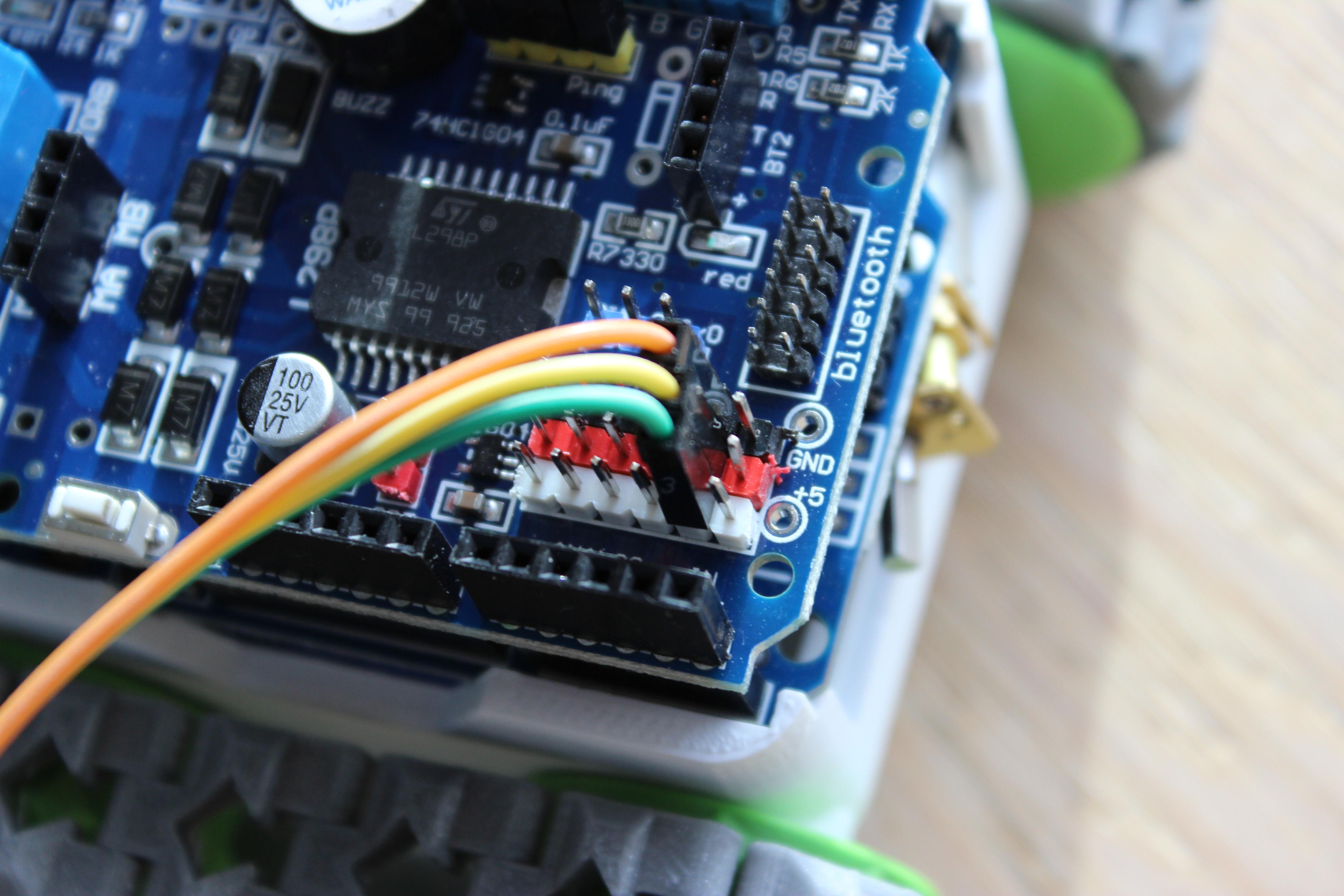
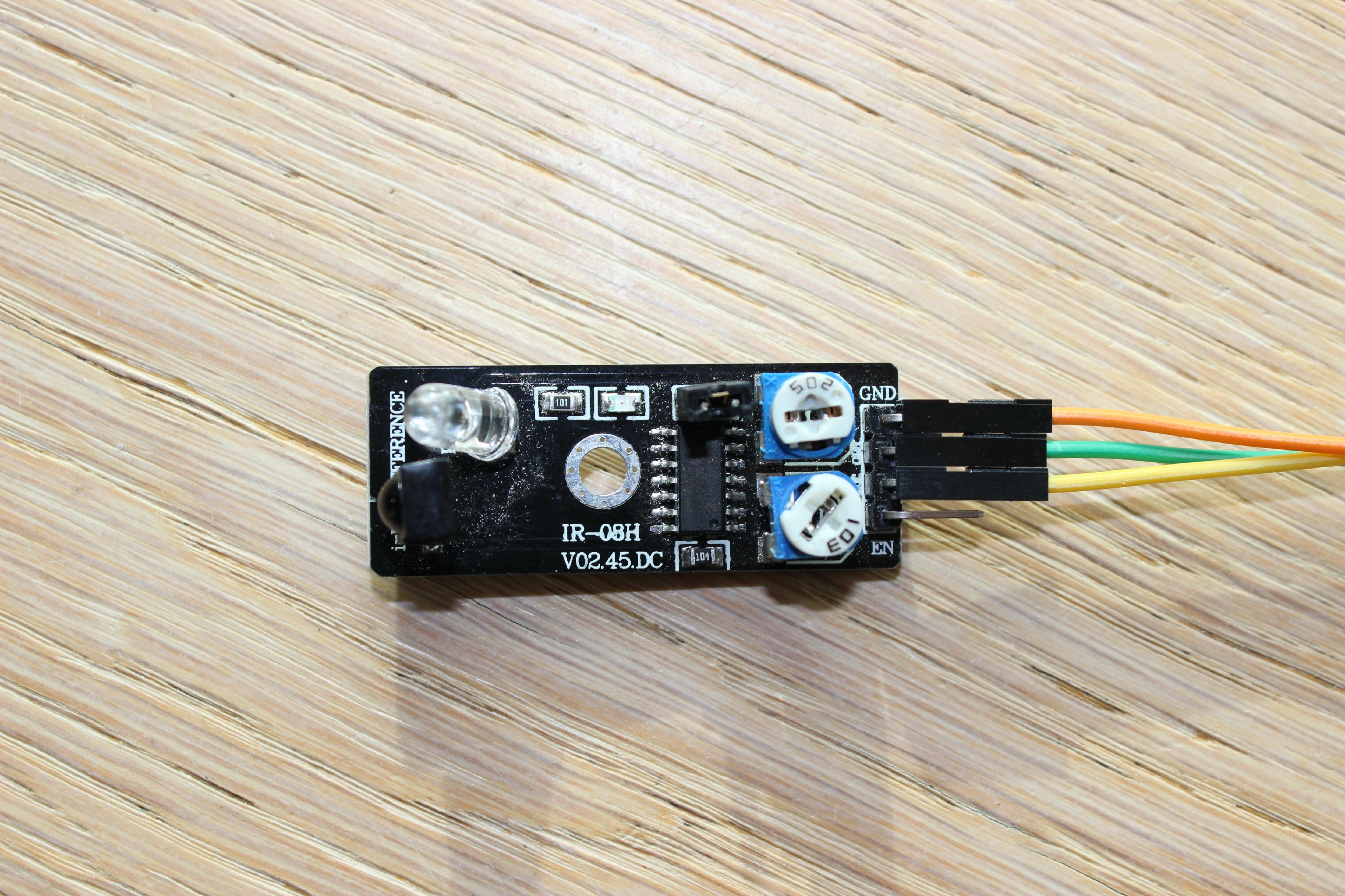
Third step consists in connecting the infrared sensor to the board. IR sensor's pins have to the connected as follow:
GND --> GND
OUT --> A4 (white pin)
VCC --> +5
Be careful, sensor connections are not in the same order, VCC and Signal are flipped!
IR Sensor Calibration
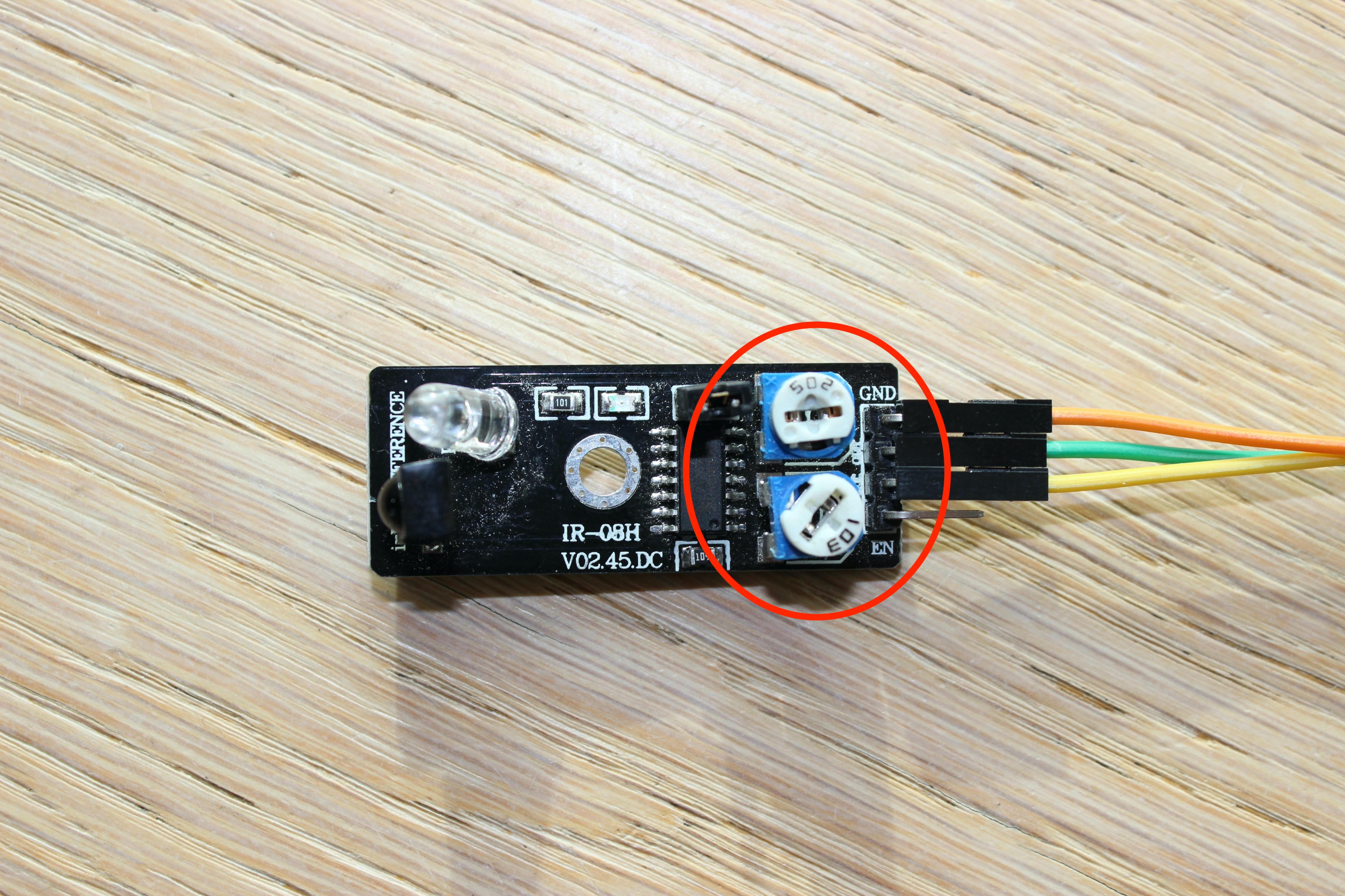
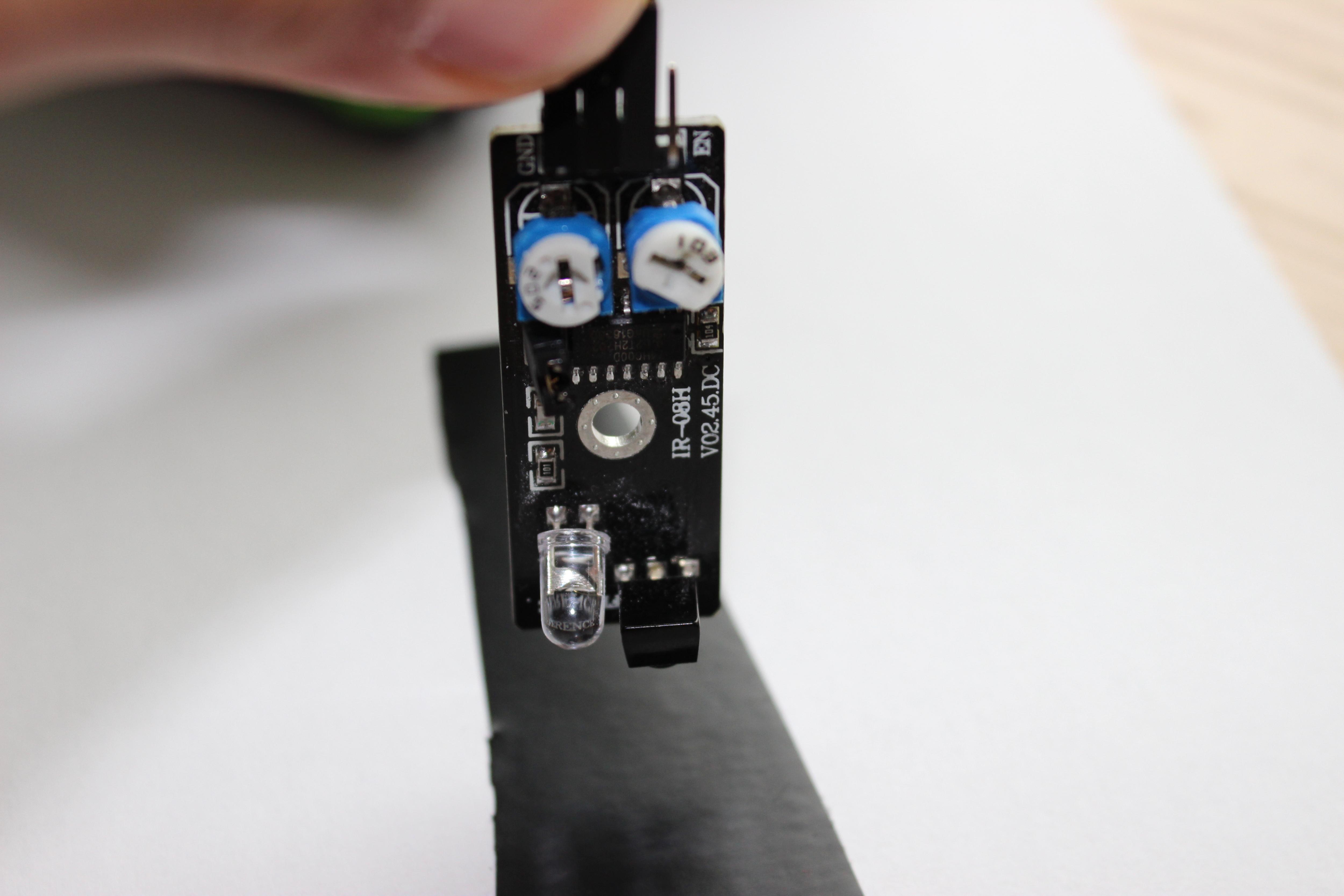
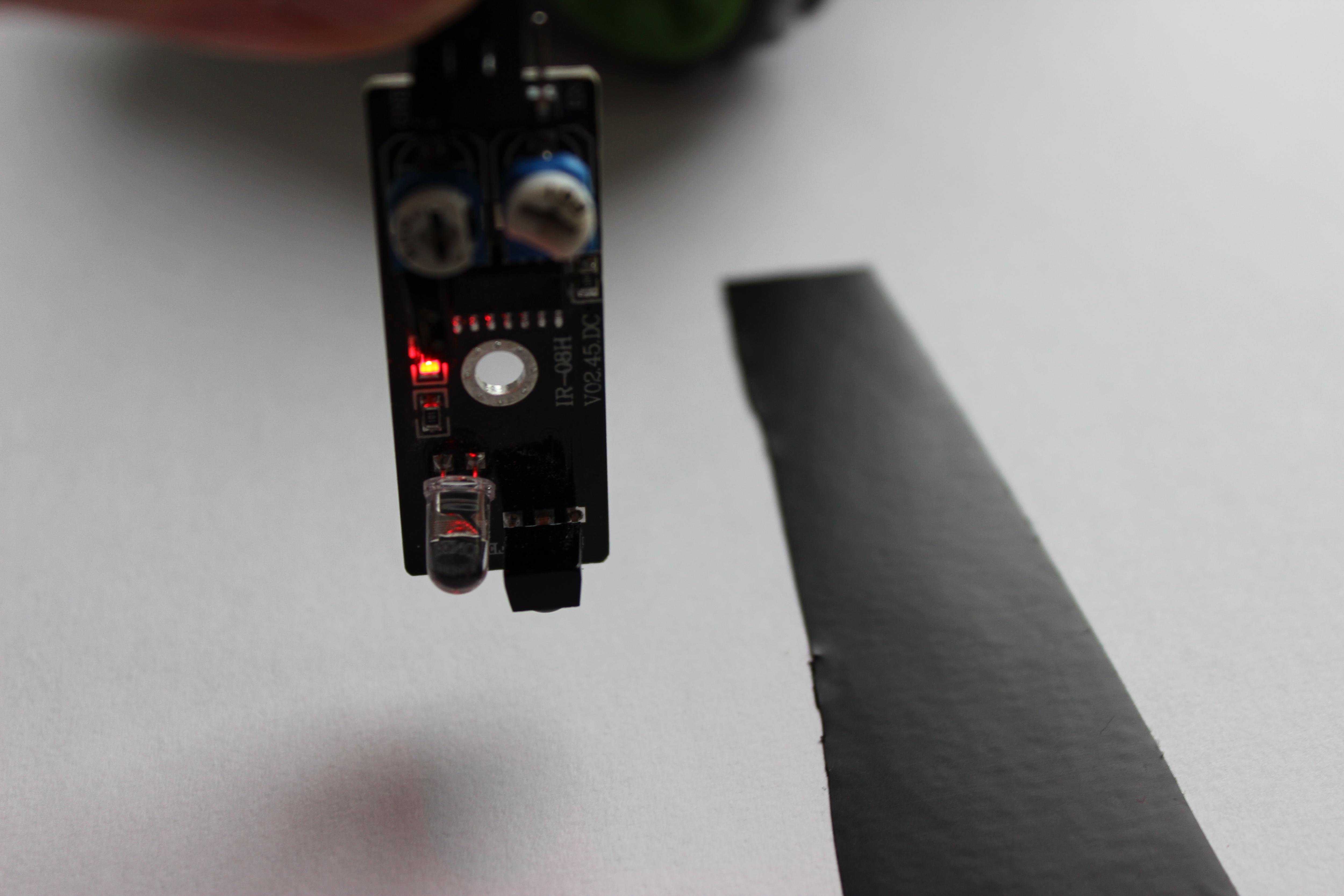
In this step we'll calibrate the IR sensor to make it able to detect a black line. To do it will have to put a piece of insulating tape on the A4 sheet, power up the sensor (connecting the 9V battery or the USB cable to the Arduino) and with a screwdriver start to adjust the 2 potentiometers on the sensor until the red light on it will turn on when sensor is on sheet and turn it off when you move it on the tape.
Uploading Demo Codes
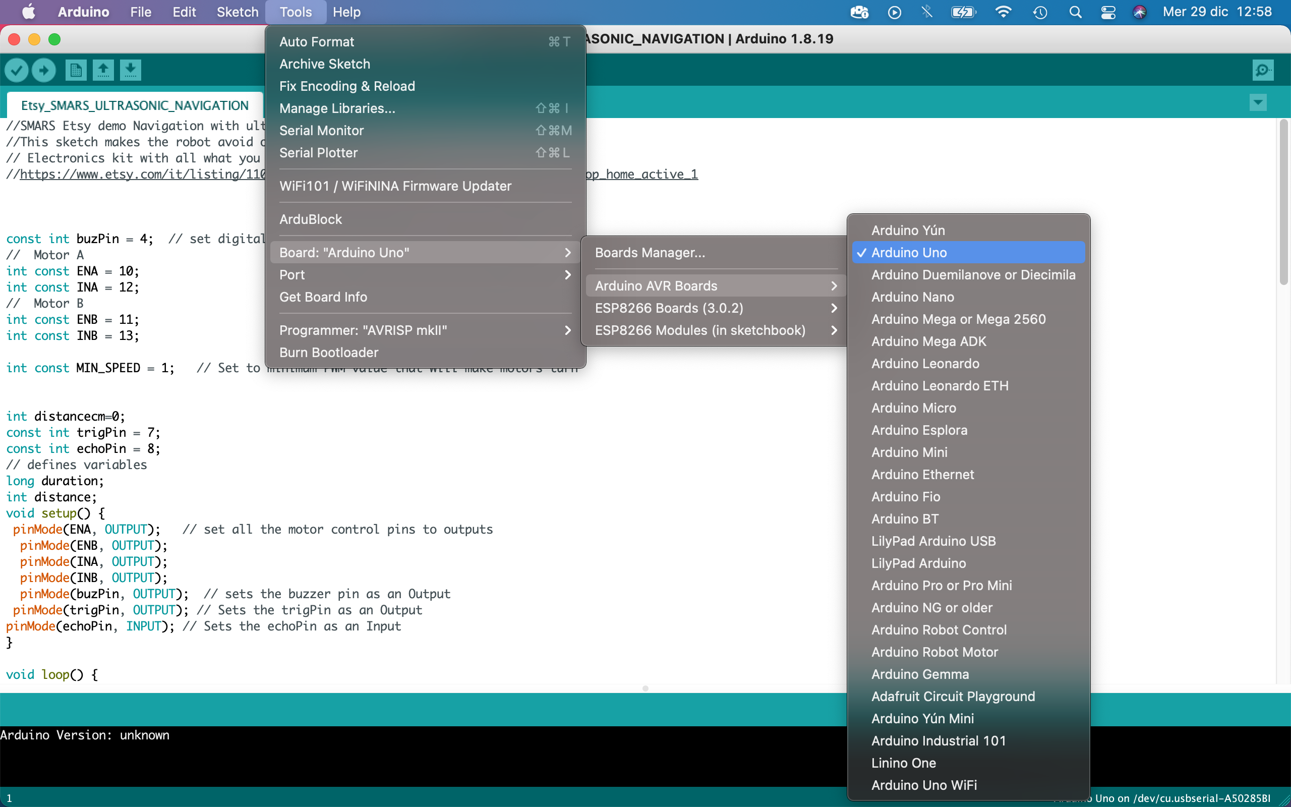
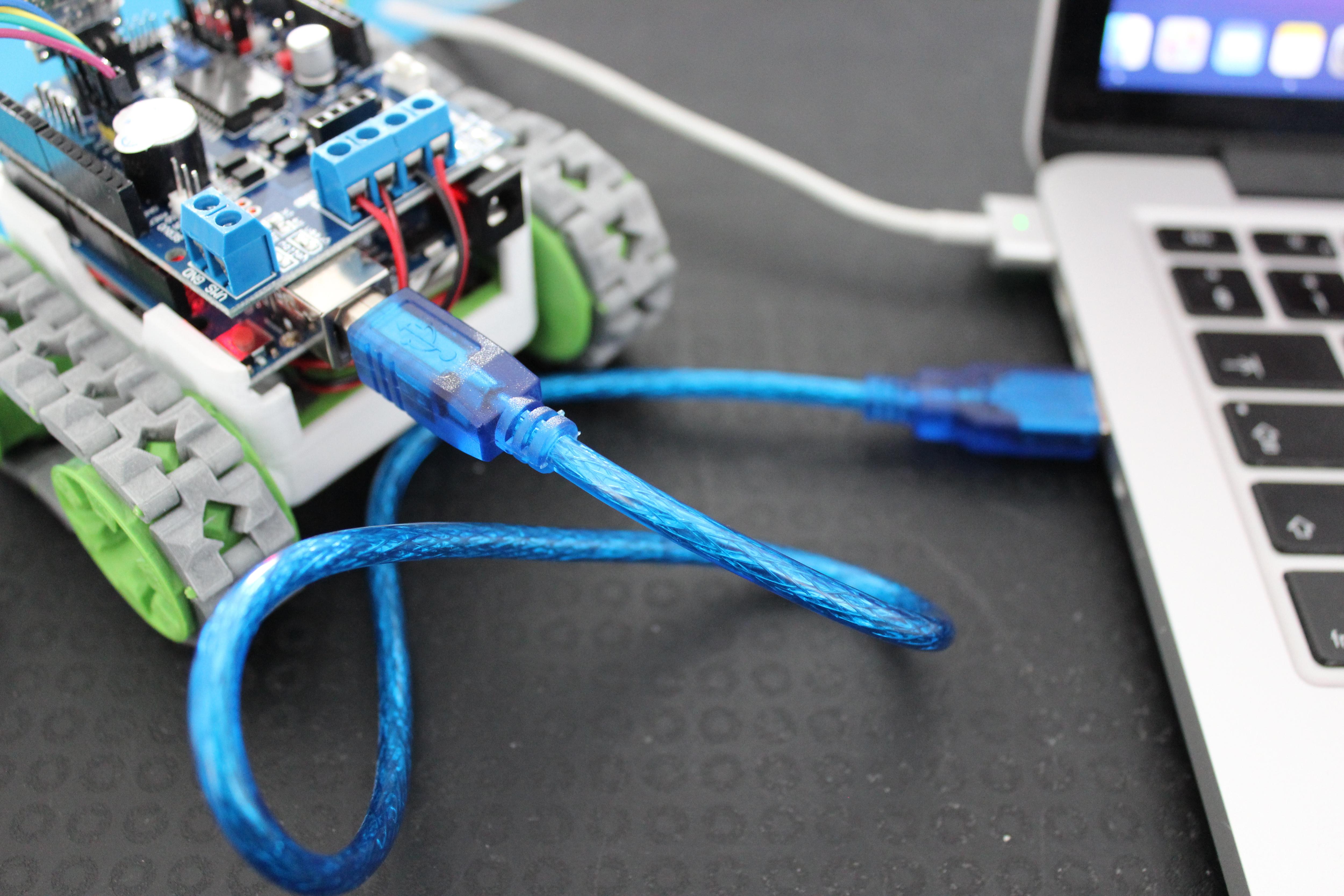
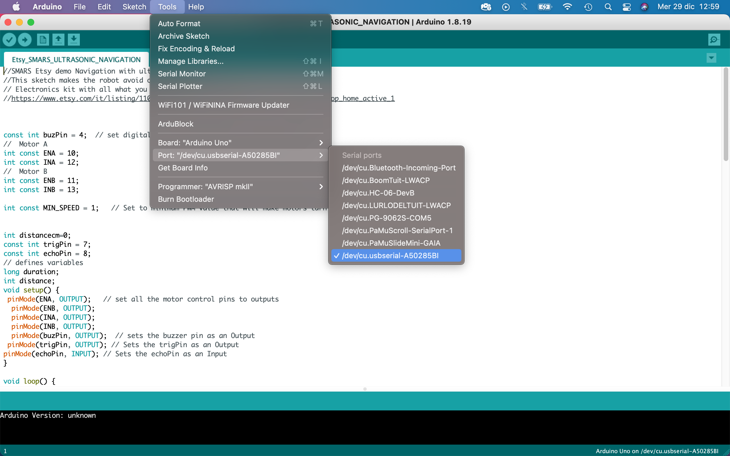
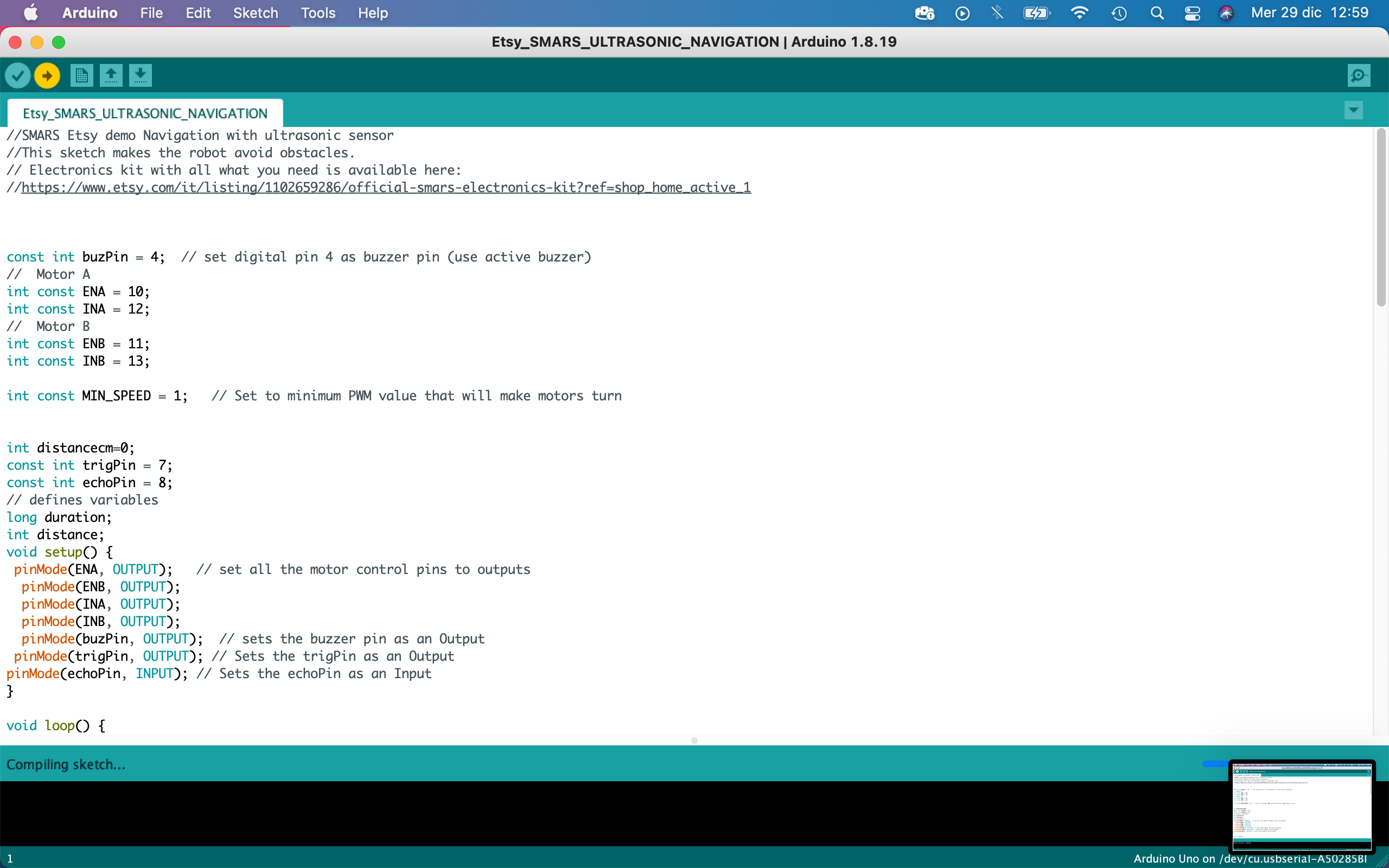
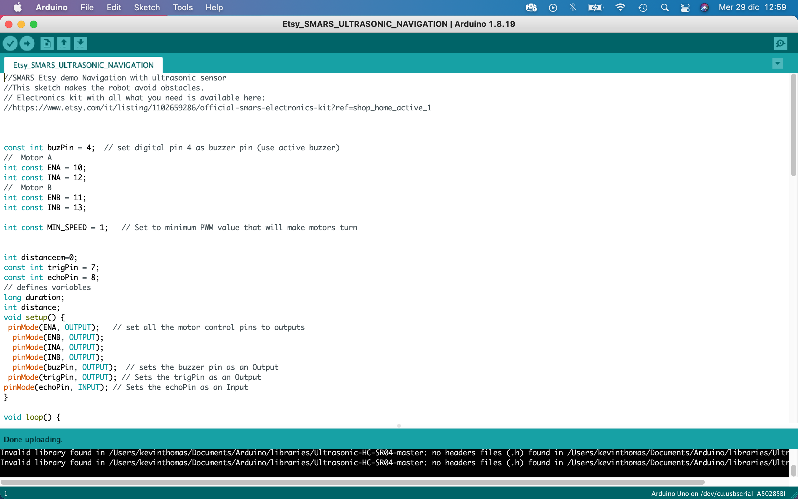
Download and install Arduino IDE (if you will have problems with the drivers, have a look here https://www.arduino.cc/en/Guide/DriverInstallation)
- Open the demo file "Etsy_SMARS_ULTRASONIC_NAVIGATION.ino"
- Go on " Tools --> Boards --> Arduino AVR Boards" and select "Arduino Uno"
- Connect your SMARS to PC with USB cable
- Go on "Tools --> Port " and select the port it just appeared, could be a "COMn" or something with "serial port" in it
- Press "Upload"
- If everything went well, the message "Done uploading." should appear in the left bottom corner of the page and your SMARS should start moving
- Unplug the USB cable, plug in the 9V battery and watch your SMARS exploring the room avoiding obstacles!
- Repeat the previous steps to upload the other demo codes and watch your robot behave differently.
Bluetooth Remote Control
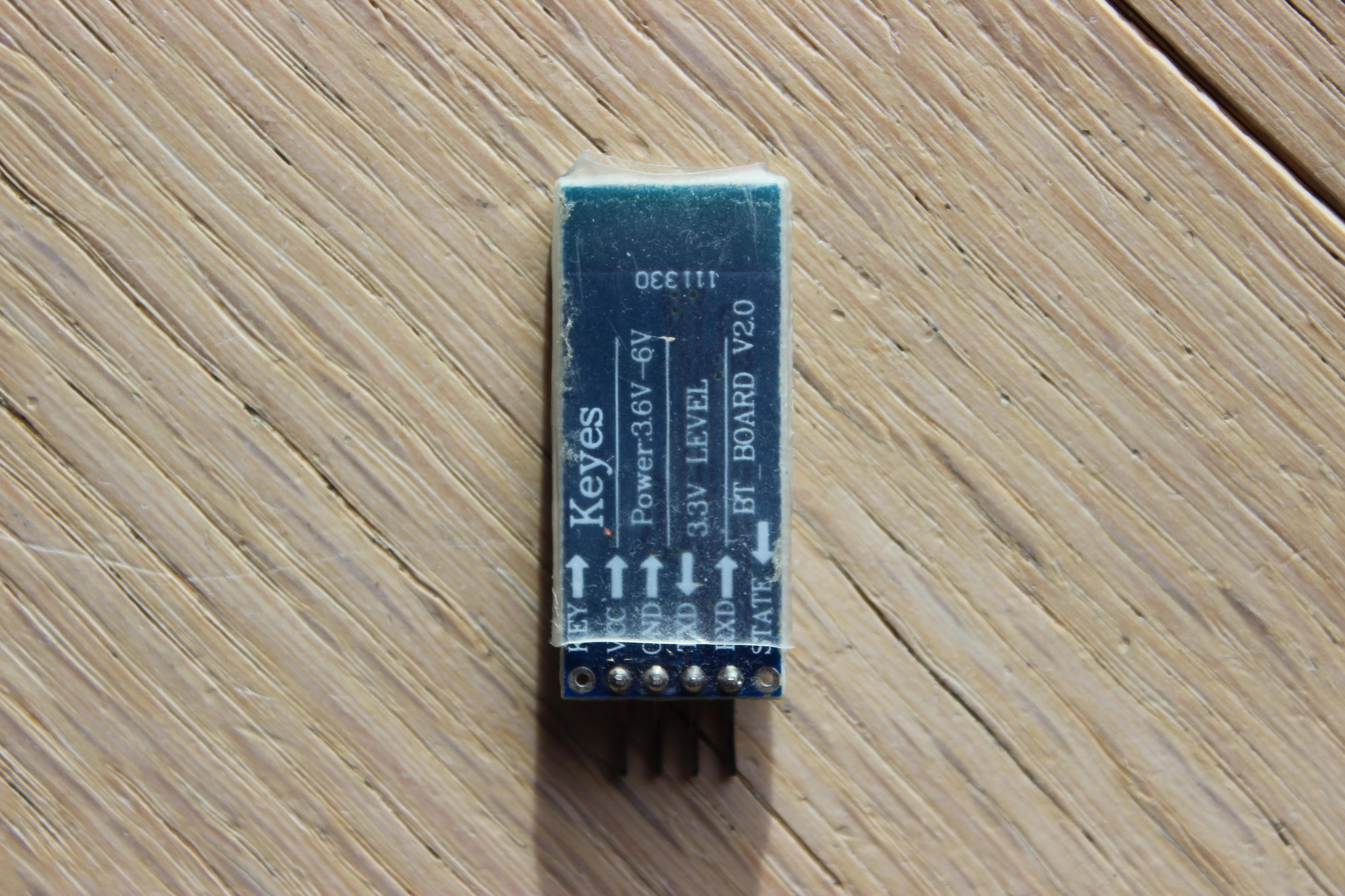
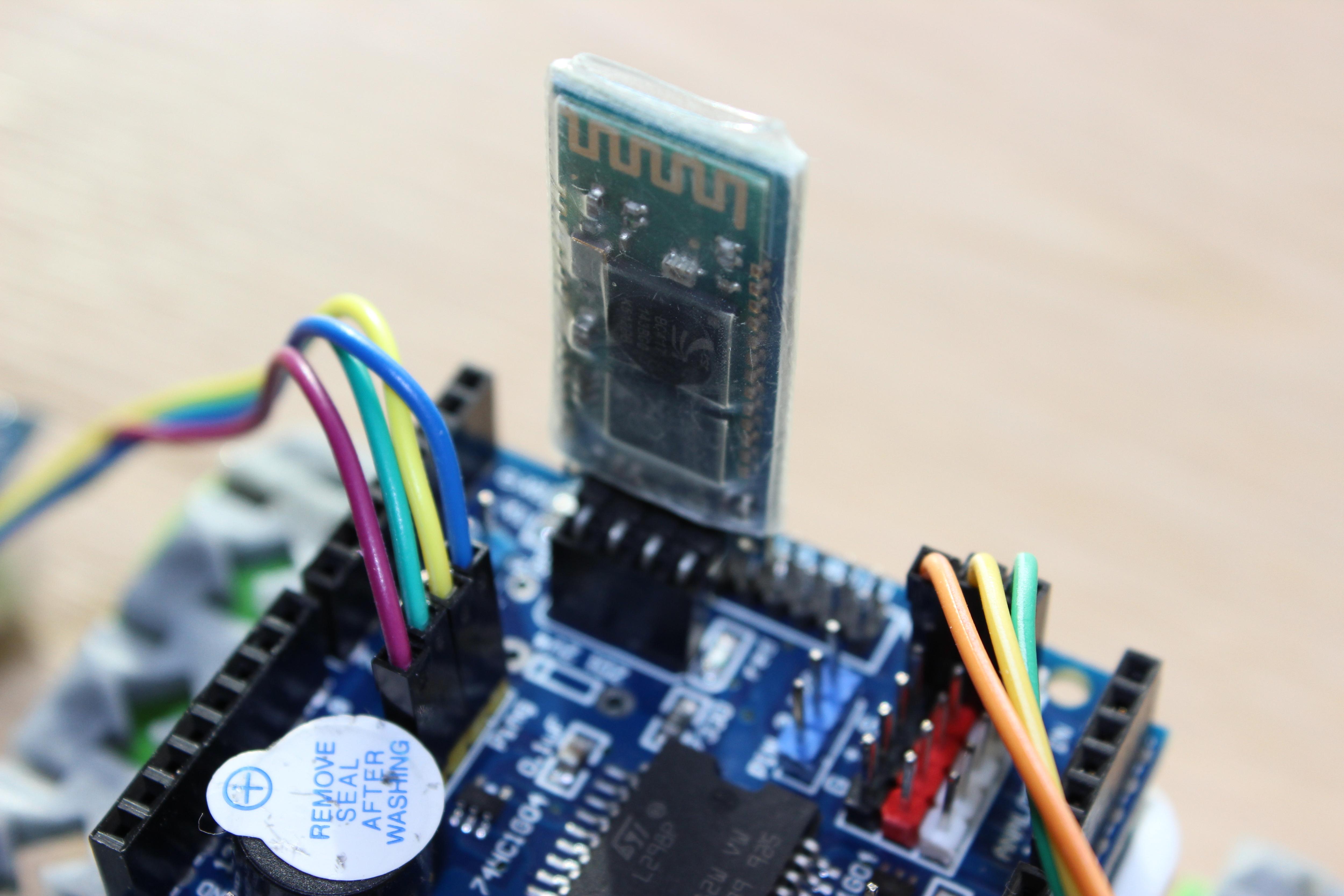
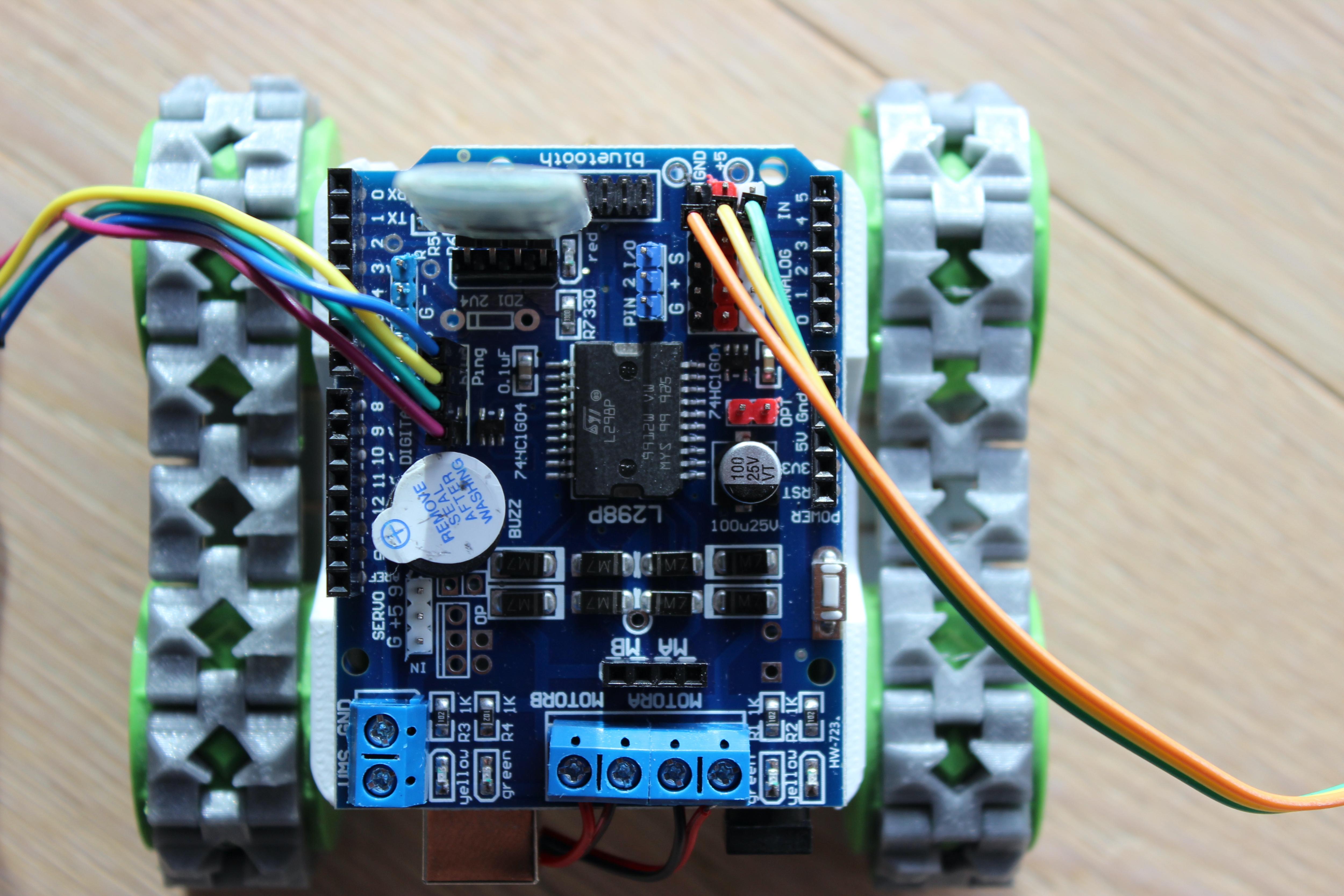
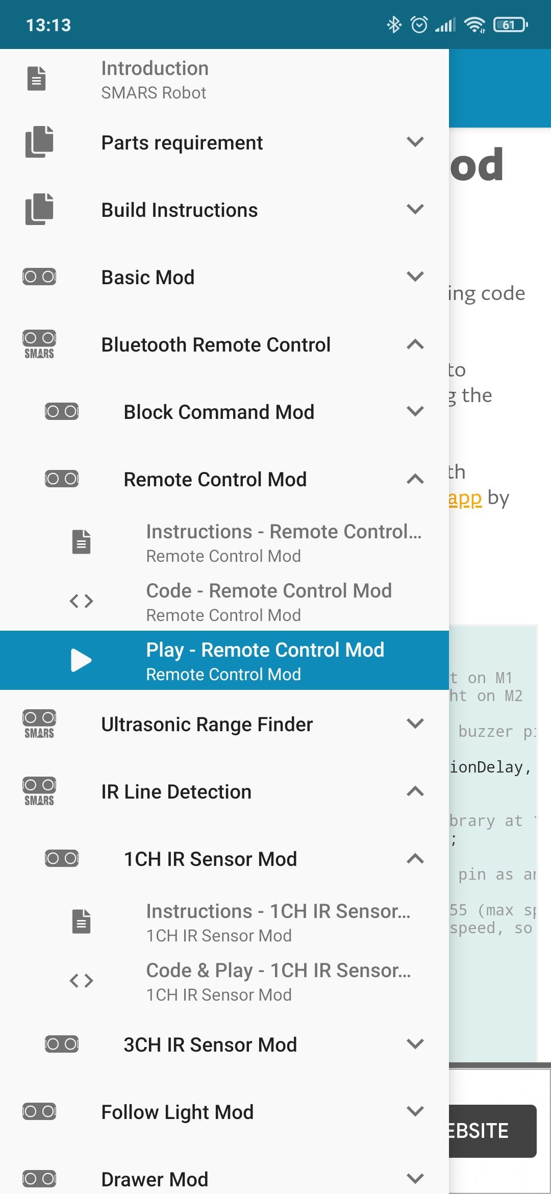
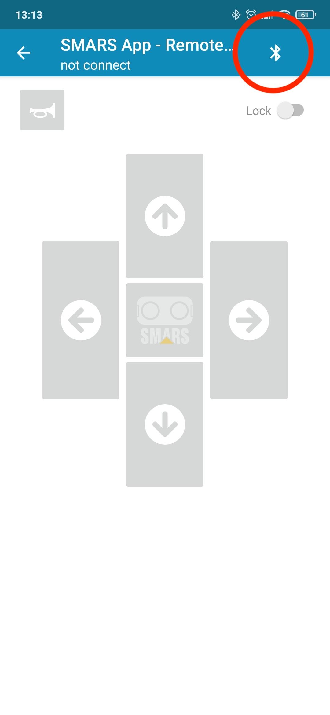
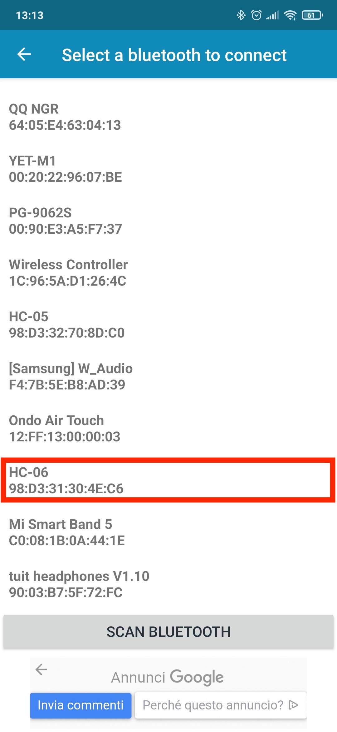
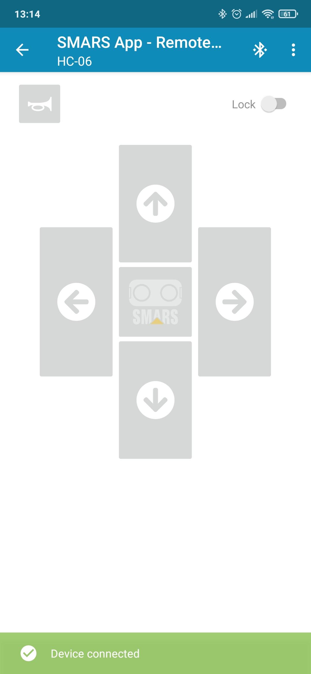
In this step we are going to add bluetooth remote control to the robot.
- First thing to do is to repeat the previous step and upload the code "Etsy_SMARS_BLUETOOTH _RC_.ino"
- Connect the bluetooth module as shown in the pics
- Download and install the SMARS APP on your phone
- Power up your SMARS and pair your phone with the bluetooth module. It's possible that it will ask for a pairing code, it should be "1234" or "0000".
- Open the SMARS APP and go to "Bluetooth Remote Control --> Remote Control Mod --> play-Remote Control Mod
- Press the bluetooth logo button and select HC-06 from the devices list
- Wait for "Device Connected" message
- Control your SMARS
Downloads
Troubleshooting
In this step we will talk about the main mistakes you could have done and try to find a solution.
- The robot doesn't move in the right direction
- you probably inverted the motors connections.
- if it turns on itself instead of going forward you have to flip the cables of the motor going in the wrong direction ( example: move L+ from A+ to A- and L- from A- to A+).
- if it goes backward instead of forward, you have to flip the cables of both motors by keeping the same ports ( move L+ from A+ to A- and L- from A- to A+, same with R and B)
- if it turn left instead of right you have to switch the ports by keeping the same cables position ( connect red cable of the motor to B+ instead of A+ and connect black to B- instead of A- and the other way around)
- The robot doesn't move
- check the power supply, maybe the battery is discharged
- check if the sketch has been correctly uploaded
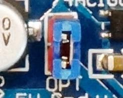
- check if the little green/blue jumper on the board is still in place (the one in pic)
- The compiler gives me an error
- check if you selected the right board
- check if you have selected the right port
- be sure bluetooth module is not connected to the board (they use the same serial pins so it will not work if its connected)
- Ask to Arduino community or google your error, it could be many things and probably you're not the only one with that issue