Wireless Safety Button for PLC Safety
by ZacharyA22 in Circuits > Wireless
5045 Views, 22 Favorites, 0 Comments
Wireless Safety Button for PLC Safety
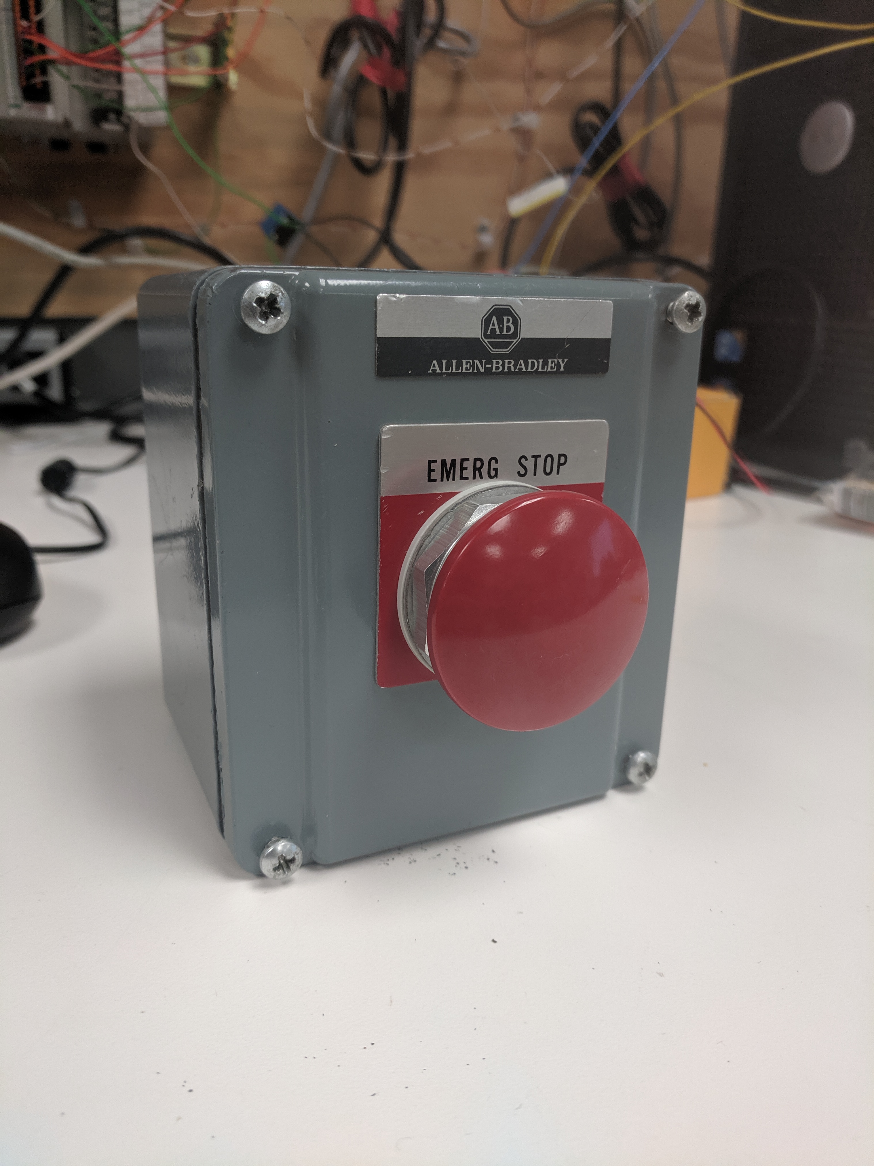
This project is my proof of concept for using IoT and (eventually) robotics to create an additional layer of safety for hazardous manufacturing facilities. This button can be used to start or stop multiple processes, including the control of signal lights. While I refer to this project as an e-stop button, please note that installing true e-stop controls requires a lot of redundancies and regulations. This project is simply meant to add an additional layer of safety.
Please use safety precautions when wiring and powering this circuit.
Supplies
Electronics
x2 NODE MCU boards - https://amzn.to/2QxJwz2
x1 PLC w/power supply - Allen-Bradley CompactLogix PLC is used in this Instructable - https://amzn.to/2QySV9H
x1 5v Electromechanical relay
x1 2N2222A transistor
x1 1k Ohm resistor
x1 normally closed (NC) push button
x1 normally open (NO) push button
x1 9v battery connector + 9v battery
Assorted wire
Software
Arduino IDE
Studio 5000
NODE MCU Server Circuit Wiring
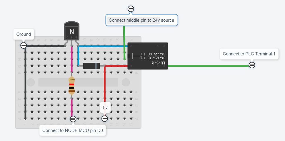
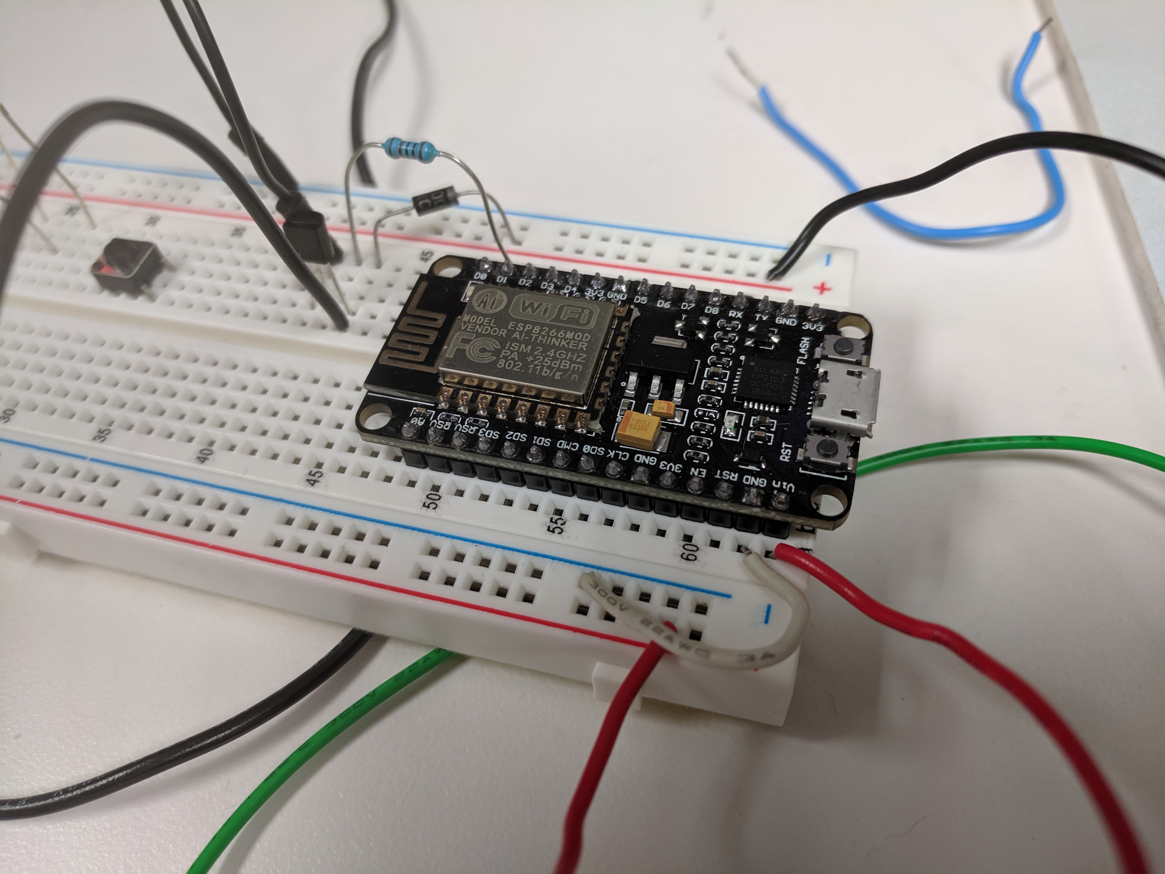
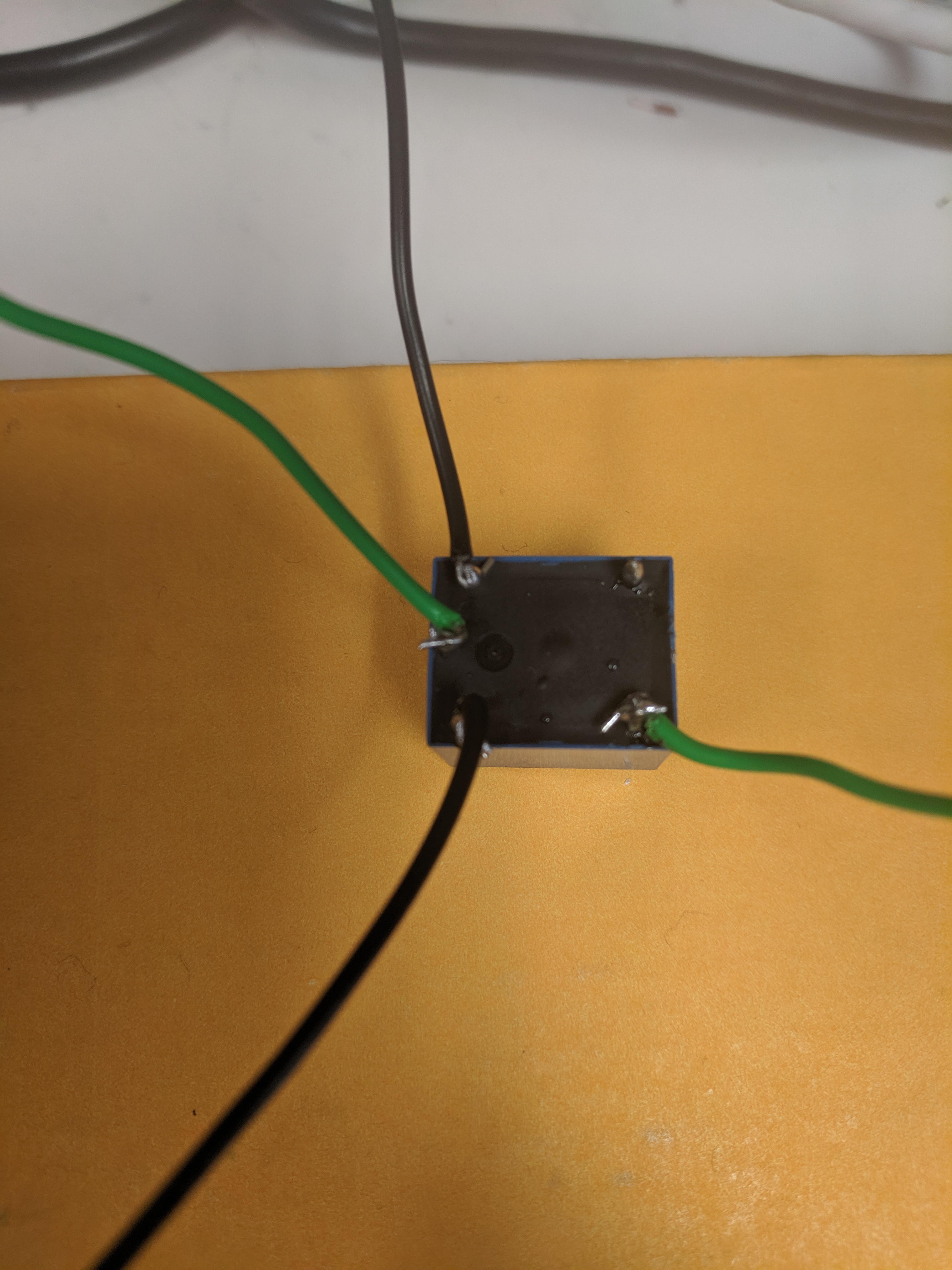
A NODE MCU board will be used as the server, and is the middleman between the button and the PLC. When the button is pushed, the server will receive a signal, which will energize a relay, and send the necessary signal to the PLC to stop all processes.
Board Wiring
To power our NODE MCU, simply use a micro usb wall adapter.
Relay Crash Course
The relay consists of two parts; the coil, and the armature. The coil can be energized, which creates a magnetic field, which will cause the armature to move from the normally closed (NC) position to the normally open (NO) position.
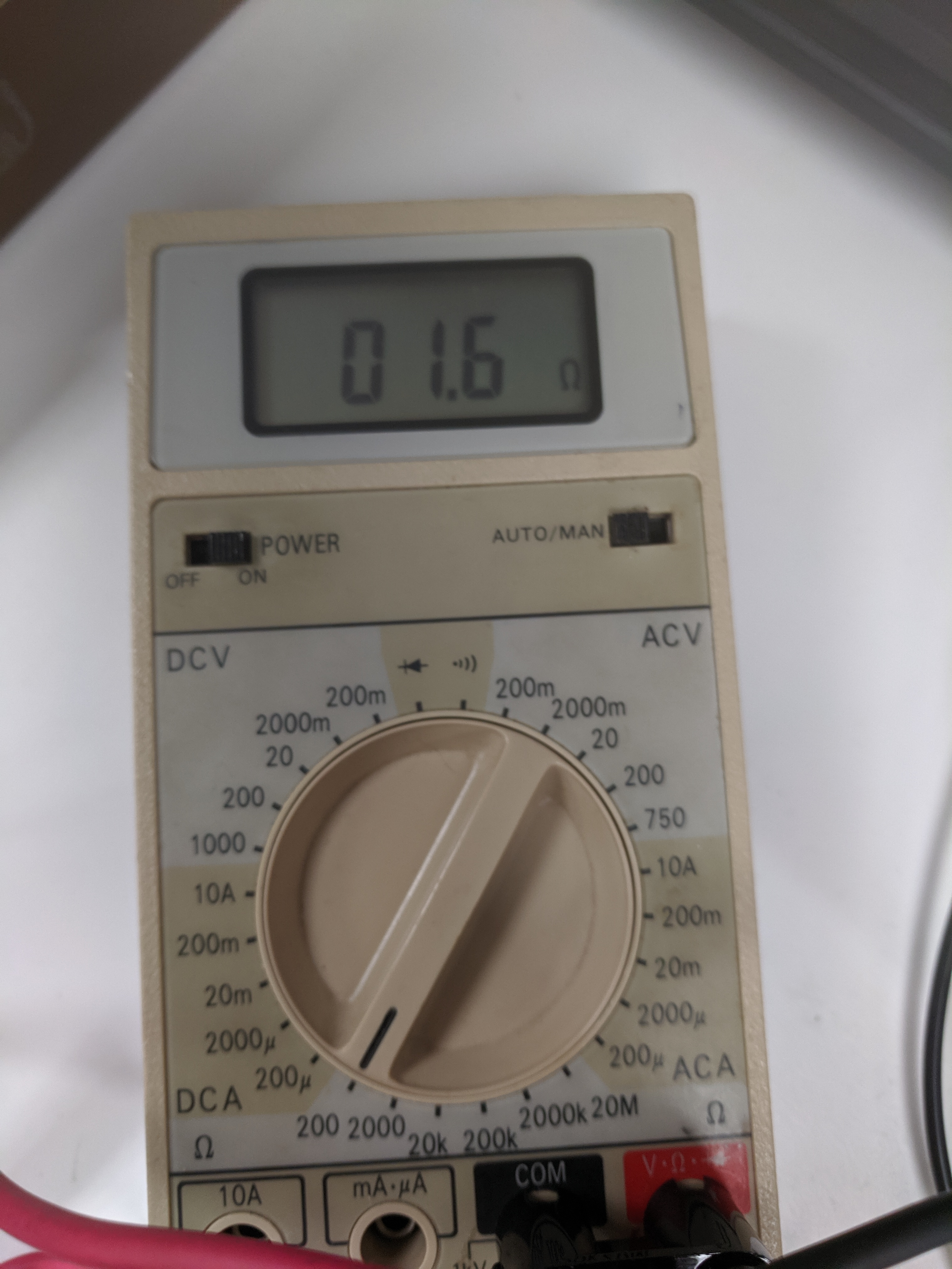
To determine which pin is NO and which is NC, use a multimeter and set it to measure resistance (2k Ohm range). Touch the red lead to the middle pin, and then measure each of the opposite pins. The NC pin will be electrically connected, so you should see a small resistance reading. The NO pin will not be electrically connected, so the reading should be over range.
Once the NO and NC pins have been established, solder or attach two wires to the coil (black wires in the picture above), one wire to the middle contact pin, and one to the NC pin (green wires).
Board to Relay Wiring
We now need to connect our relay to the board. We need to supply 5v to the relay coil in order to engage the armature. Since the NODE MCU board only outputs 3.3v, we need to use a transistor to amplify the signal. Refer to the wiring diagram for circuit connections. Please note that if a different pin is used for the signal, it will need to be changed in the code.
Relay to PLC Wiring
Wire the central pin to the 24v source, and the NO pin to input terminal 1 on the PLC.
NODE MCU Client Wiring
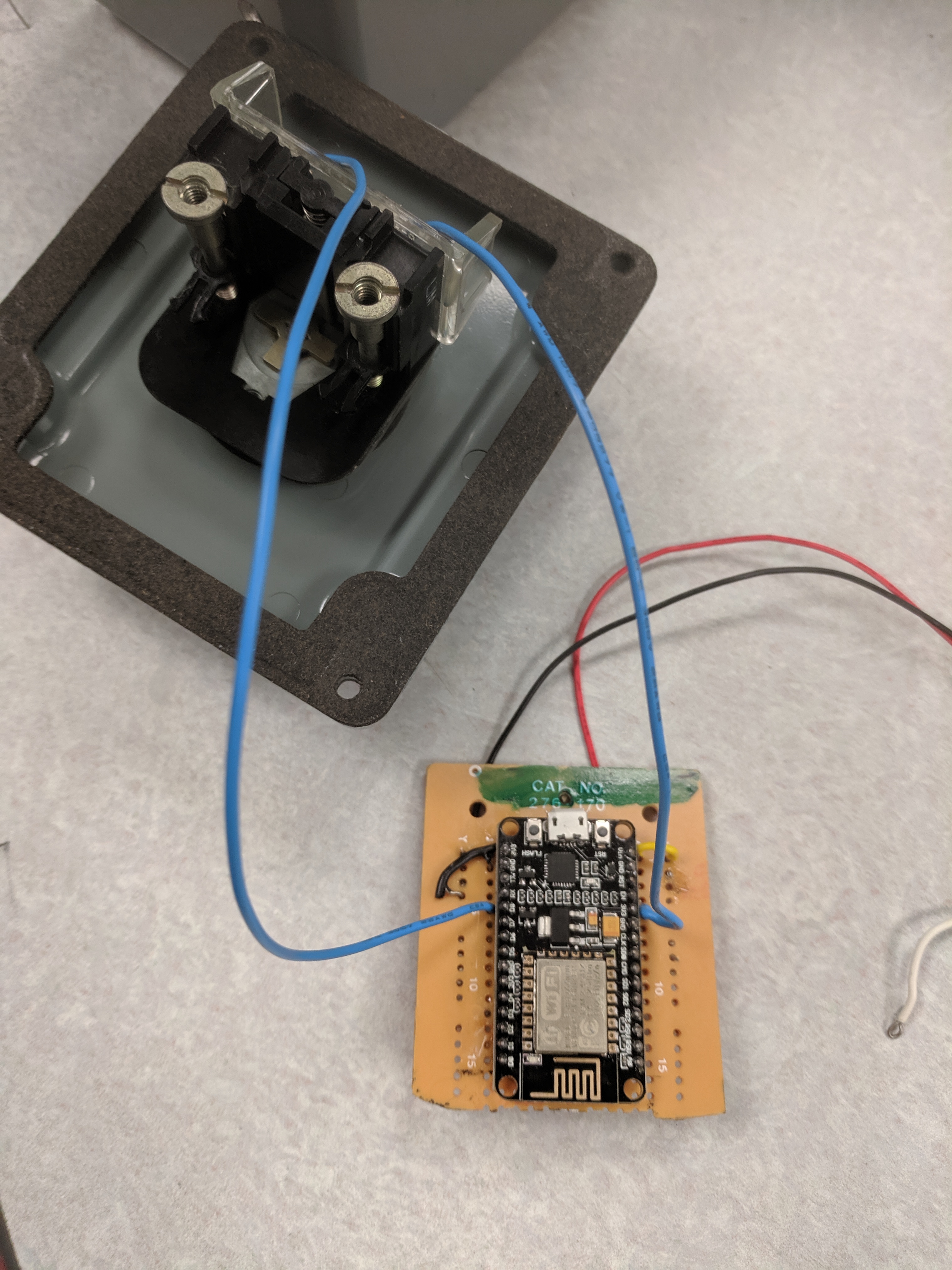
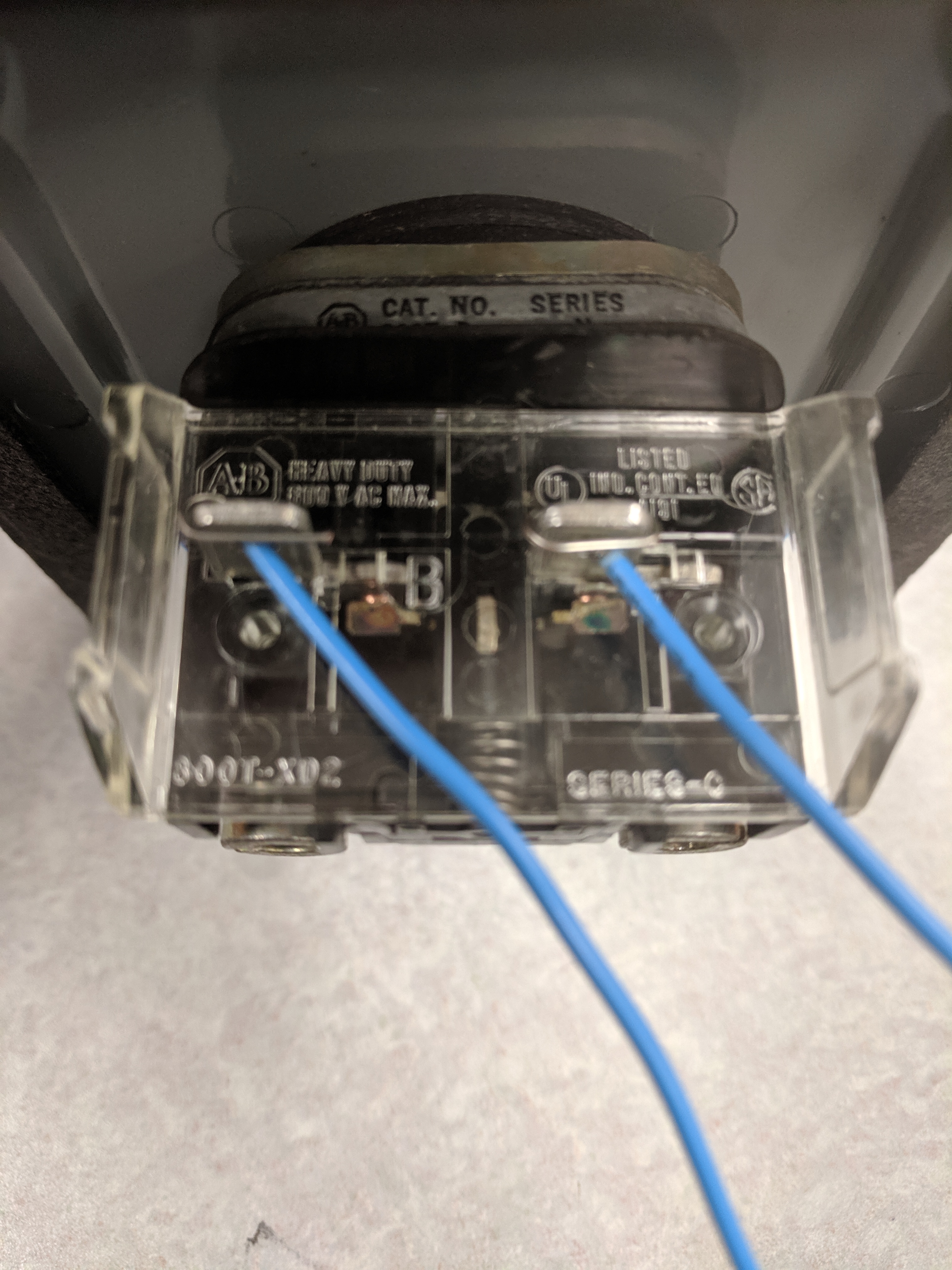
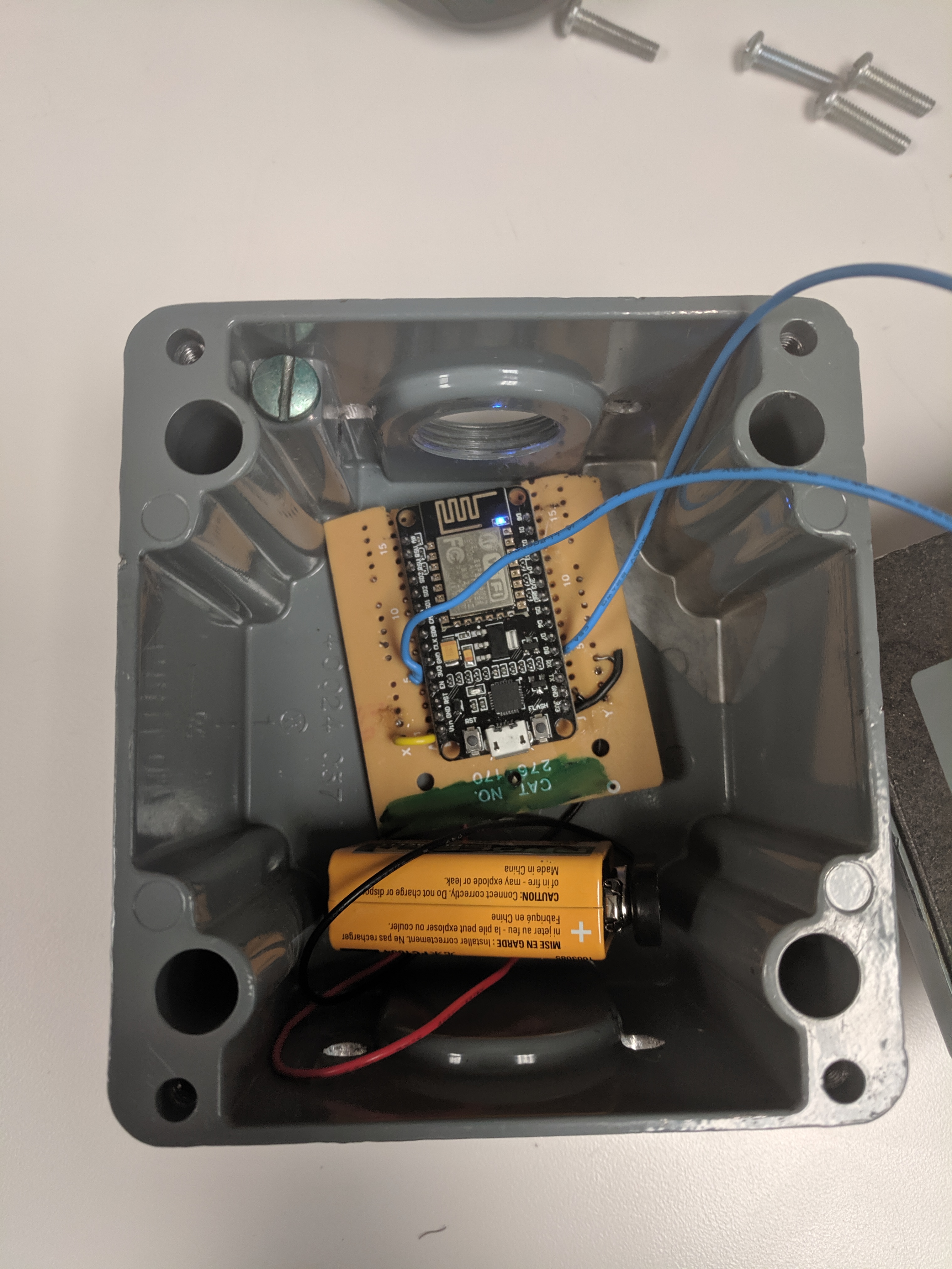
This NODE MCU board will be programmed as the client, and will send the button status to the server. Connect the 9v battery to Vin and GND pins on the NODE MCU. Solder/attach a wire from any pin labeled 3v3 (3.3v pin), and another wire to pin D8 (GPIO 15). Solder or attach the other end of these wires to either side of the normally closed emergency button.
PLC Wiring
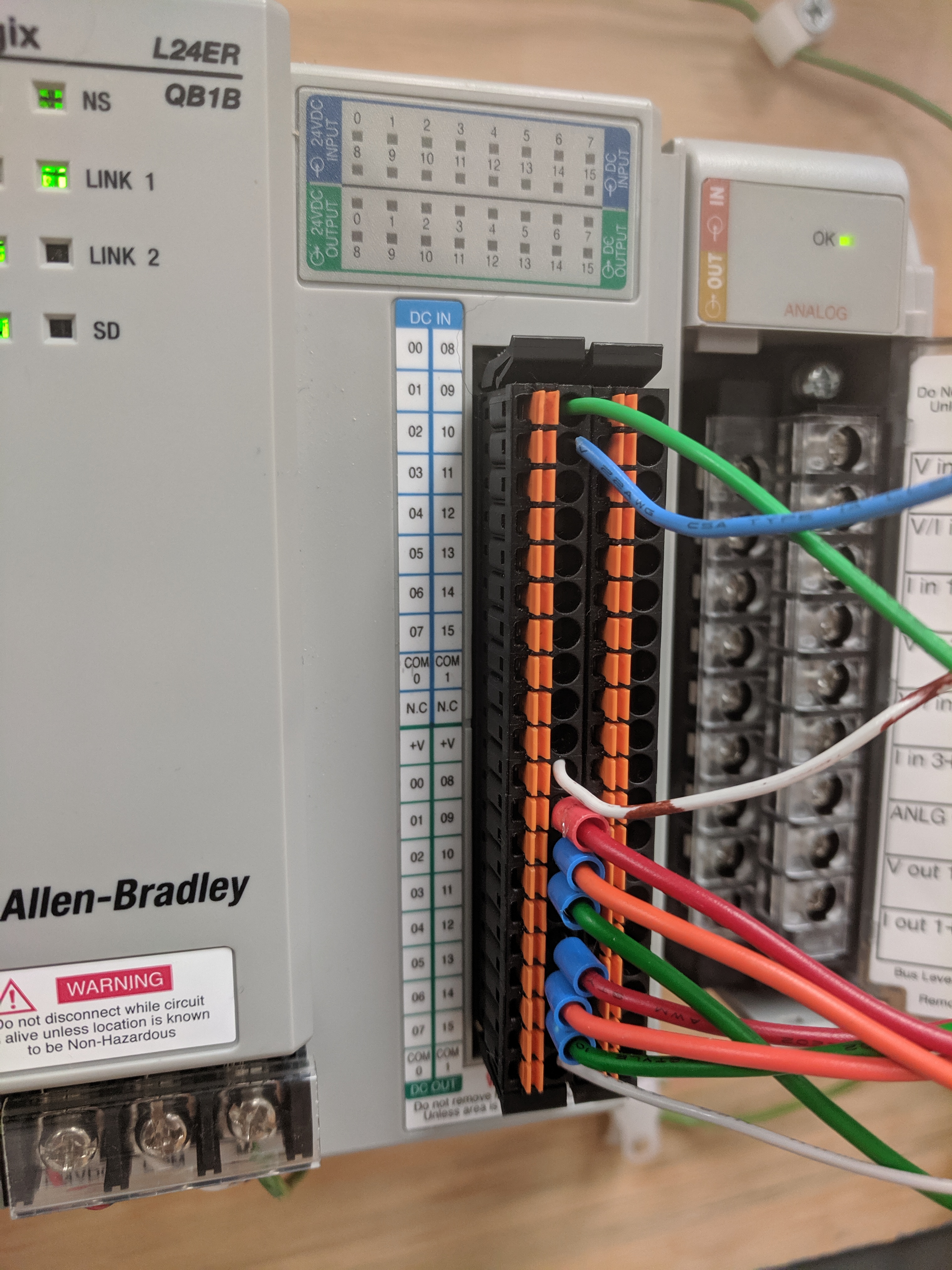
Plug your green wire from the NC relay leg into input terminal 0 of your PLC. Make sure you have a connection to ground via the common (COM) port associated with your input. Most PLCs have separate COM ports, so be sure you're wired to the right port.
Do the same with a normally open push button to act as our start button for our PLC. Attach this button to terminal 1.
Plug in any number of output devices that can handle 24v into the output terminals. For this example, we are using a single pilot light in output terminal 0. Be sure to add a connection to ground at COM.
Programming NODE MCU Server and Client
If this is your first time using the NODE MCU boards, use this setup guide: https://www.instructables.com/id/Quick-Start-to-No...
Once you're setup, download the server and client files. The necessary changes are listed below, as well as in the .ino files.
1. Change the SSID to your network name for both server and client
2. Change the password to the network password for both server and client. If it is an open network, leave it as "".
3. For the server, include the IP, gateway, and subnet mask.
4. For the client, include the IP address used for the server.
5. If both boards are wired as shown in the previous steps, simply upload the files to the respective boards. If different pins are used, change the respective variable, then upload.
Program the PLC
PLC Crash Course
PLCs use a fairly simple I/O language known as ladder logic. Code is read from top to bottom, and from left to right. During each program cycle, true/false input data is updated, and that information is used to control the outputs. Inputs and outputs in the ladder logic program are tied to discrete terminals on the PLC, which are wired to field devices.
The symbols used are as follows:
--| |-- Examine if closed (XIC). This is an input contact, and it will be true if there is a HIGH signal at the corresponding input terminal.
--|/|-- Examine if open (XIO). This is an input contact, and it will be true if there is a LOW signal at the corresponding input terminal.
--( )-- Output. This is an output contact, and it will become HIGH while all of the input contacts on the rung are TRUE.
Explanation of Code
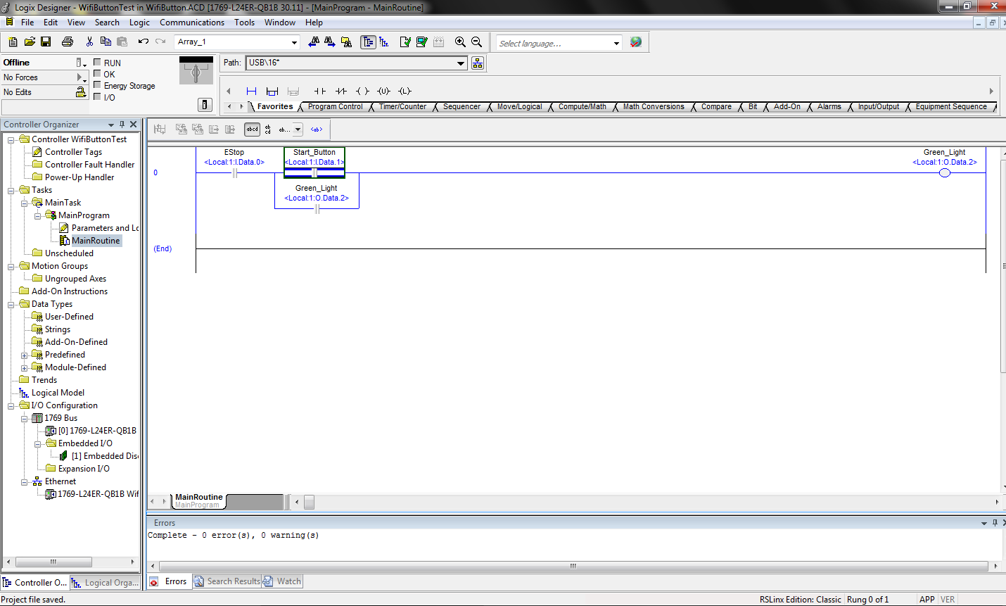
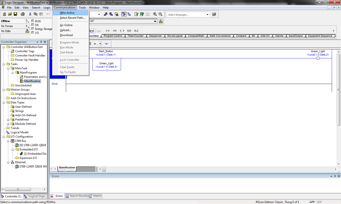
On the first rung, the first XIC contact is our emergency stop command. We use an XIC in conjunction with a normally closed E-stop button. Since the NC button provides a HIGH signal, the XIC will return TRUE, allowing the rest of the rung to be energized. Pressing the E-stop button will break the HIGH signal, and force the rung to de-energize, thus stopping any dangerous machinery that may be running.
The next part of the circuit is a parallel rung that forms a seal-in circuit with the output coil. Parallel rungs act like an OR gate - if either are true, the rung can be true. The top contact is wired to our start button, and the bottom contact is the status of our output contact. Once the start button is pressed, the output will energize, which will make the bottom contact TRUE. So the user can release the start button and the output will remain energized until the E-stop button is pressed.
To program the PLC
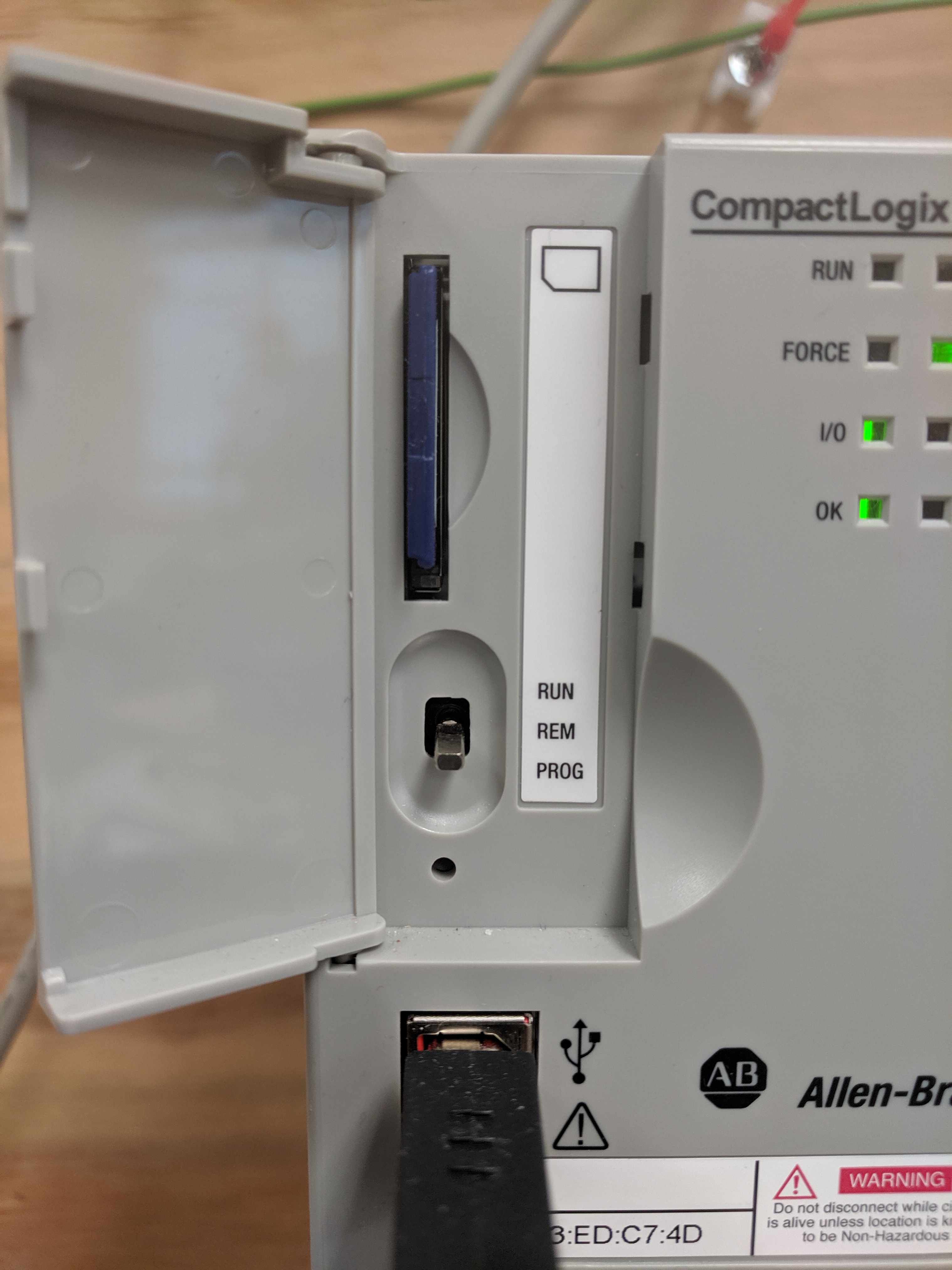
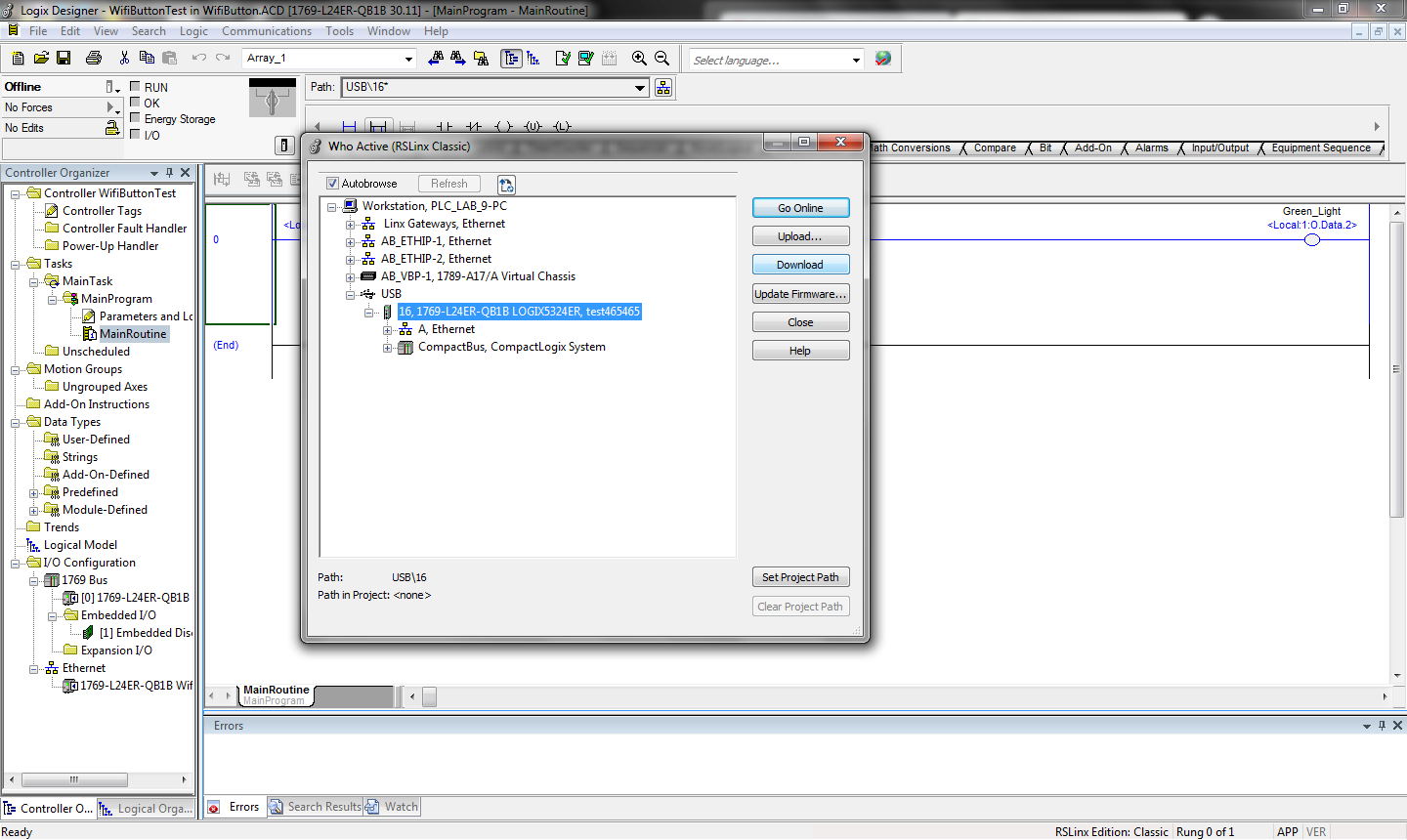
Be sure you have Studio 5000 downloaded and installed. Power up the PLC and connect it to your computer using a USB connection. Open the attached code. Select Communication < Who Active. Your PLC should be listed under USB serial port. Be sure your PLC is set to 'prog' to download. Select your PLC and download the code. Once ready, set the PLC to 'run' to run your program.
Downloads
Run It!
Attach a 9v battery to your client board. Plug in your server board and your PLC. Run the PLC program, then hit the emergency button. You should see the pilot light (or whatever output device used) deactivate.