Build a Wireless BLDC Motor Driver Using TMC6200 and ESP32S3! | High-Power Motor Control | ERAD
by RoboticWorx in Circuits > Robots
7059 Views, 37 Favorites, 0 Comments
Build a Wireless BLDC Motor Driver Using TMC6200 and ESP32S3! | High-Power Motor Control | ERAD

For the best quality read, check out this article on my homepage here. Also, don't forget to subscribe for free to support my work! :)
In this project, I will walk you through how to build a fully integrated, wireless, high-power BLDC motor driver using TMC6200 and ESP32S3 that you can use to actuate just about anything.
A Quick Preview
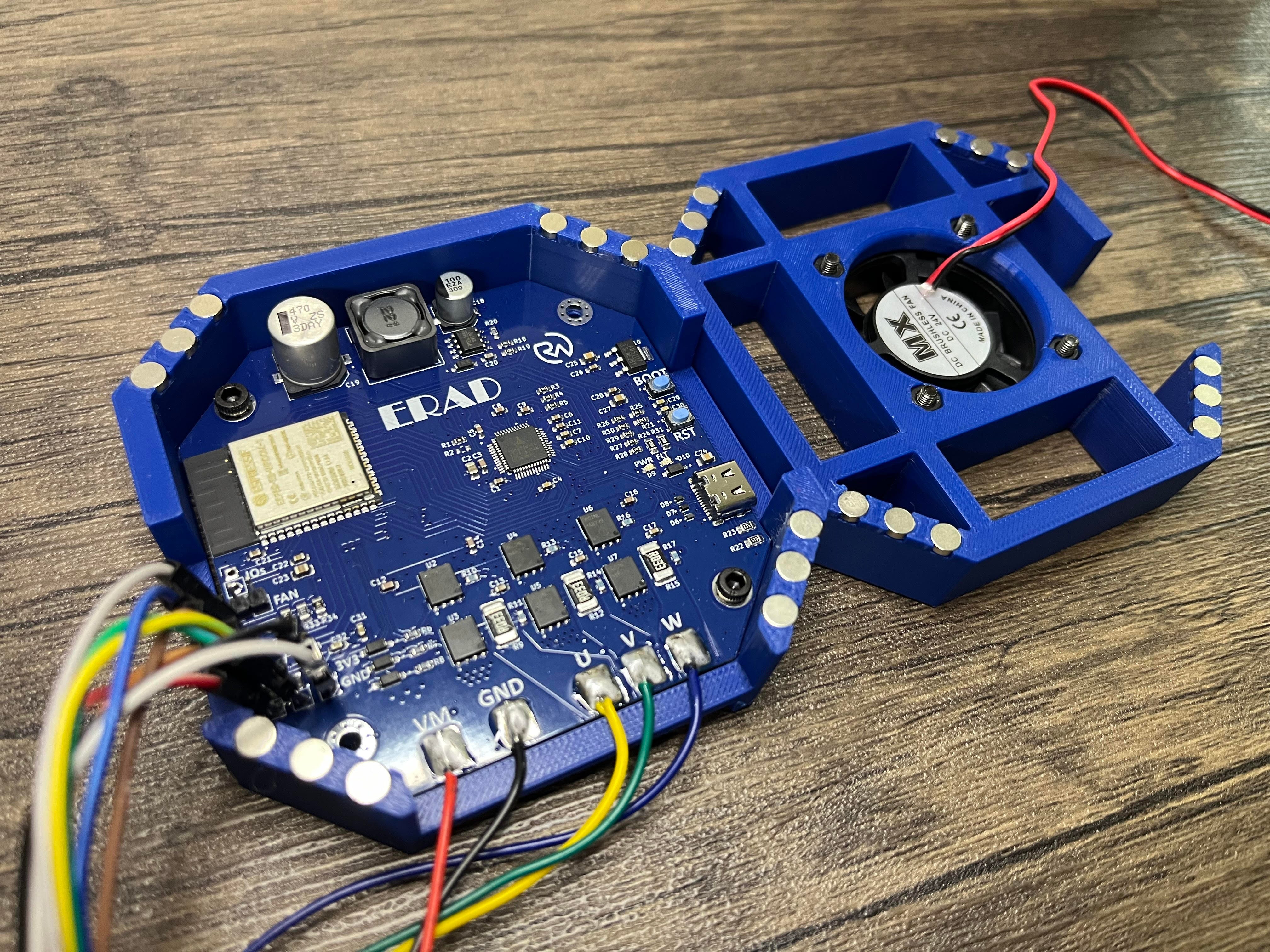
This is my “ERAD” brushless DC motor driver project! A less exciting but extremely necessary project to be used in many future actuation applications (making things move). This project features the ability to wirelessly control brushless motors with high precision and torque, allowing you to bring your projects to life!

Continued..

Note: The motor used in the first demo is an ML5010. In this next one, I’m using a 50:1 geared BLDC, which is handling 10 lbs (4.5kg) at 20cm. All of the control is handled wirelessly by ERAD!
Continued...

In a max torque test, the geared setup was measured in at a 70Nm peak! However, I should point out that the gearbox is rated for 17.63Nm so I don’t recommend exceeding that under normal circumstances.
If you have used commercial BLDC motor ESCs (Electronic Speed Controllers) in the past, you have probably noticed many challenges trying to get precise and reliable movement. The vast majority of commercial ESCs are developed for drone use which leads to problems when attempting high-torque, controlled motor actuation. That is where drivers such as this differ, excelling through the use of direct-drive control systems!

Working Concept
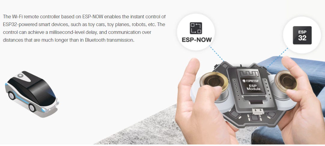
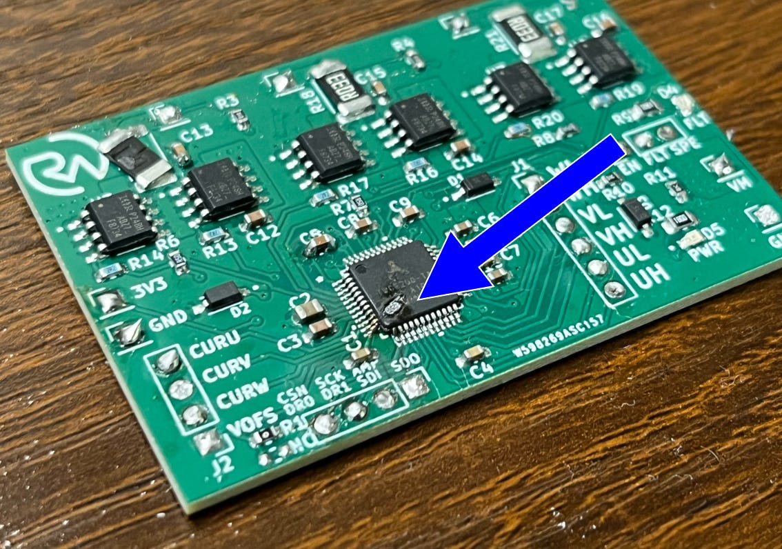
To make all of this work, ERAD (Everything Robotic Arm Driver) utilizes a TMC6200 gate driver IC and six MOSFETs to execute commutation commands from an ESP32S3 microcontroller (MCU) running SimpleFOC. If you want to learn more, I wrote an entire article about building ESP32 MCU boards here. To handle wireless communication, the board utilizes the ESP-NOW protocol. I had originally wanted to set up Bluetooth but decided to go with ESP-NOW instead because of its better many-to-many peer broadcasting capability. This means that if I want to set up multiple of these boards for one device, I can send commands to each from one central location.
After the command is received, the board listens for hall effect sensor readings to control the phases of the BLDC motor stator based on the actual position of the rotor relative to them.
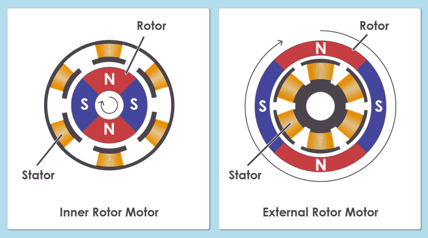
*Image: ablic.com
Typically, the most standard (open-loop) way to achieve motor commutation can be done by simply energizing the phases of the BLDC motor stator (windings) in a specified sequence.
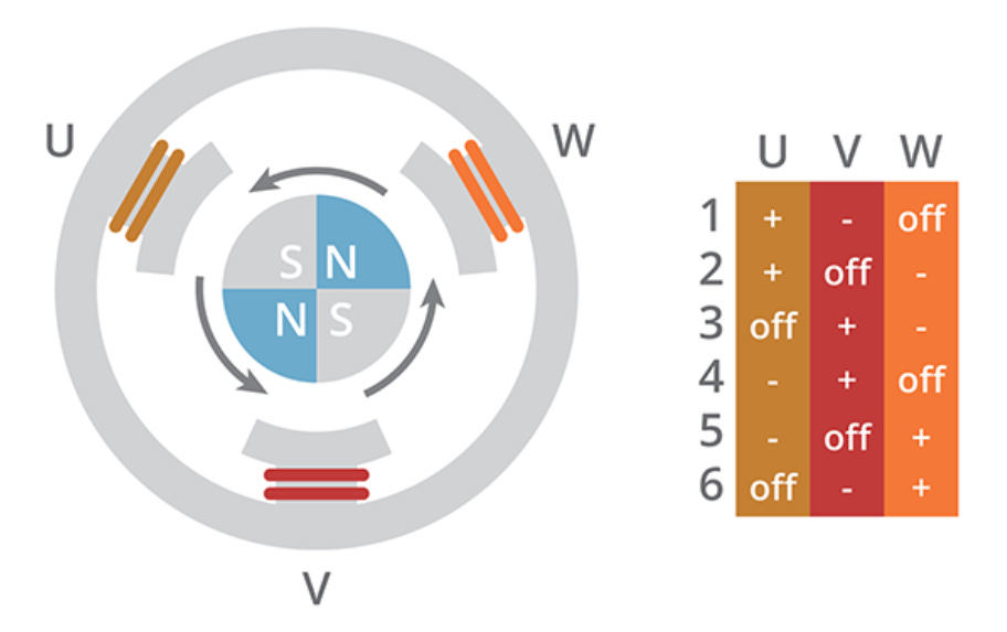
*Image: cuidevices.com
However, this alone isn’t a great way to achieve reliable movement since the rotor (the part that moves) can easily “miss” a step when under a load or at high speeds. Instead, the motor should be closed-loop controlled by incorporating hall effect sensors (or other) to notify the electronics of the rotor’s actual position instead of where it theoretically should be.
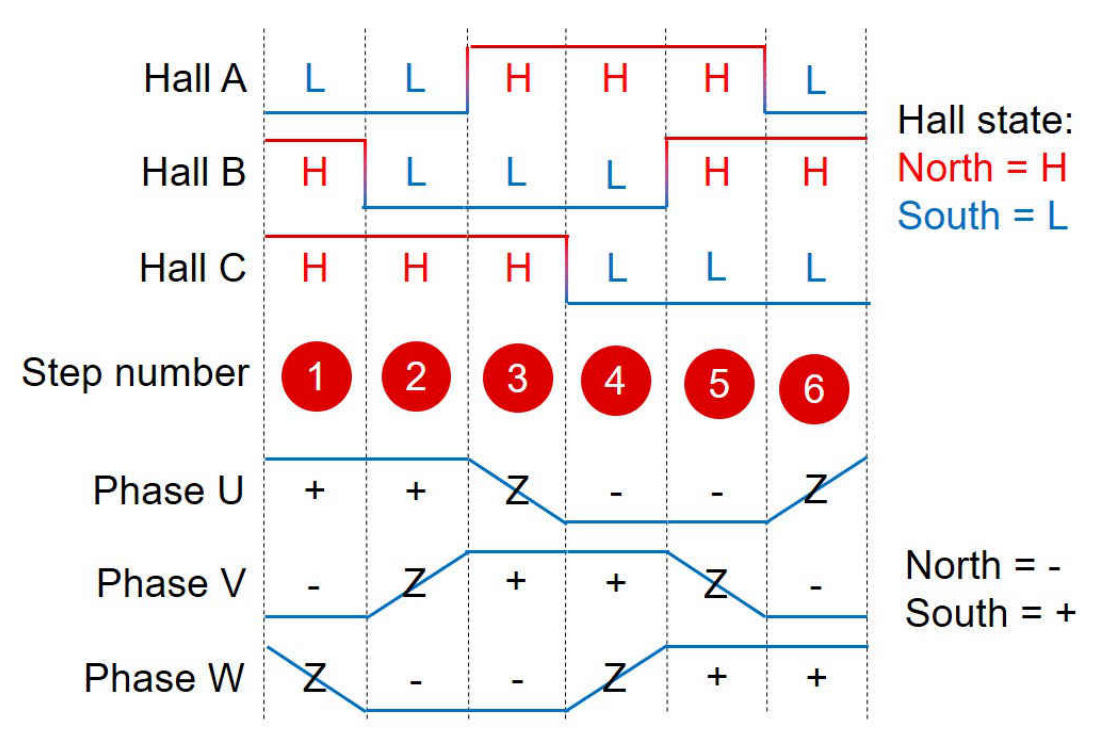
Performance can also be increased by “easing” in and out of the motor phase’s Hi-Z (unconnected) state (such as shown above) to grant a better attraction as the rotor approaches the stator coil. The torque of the motor can also be controlled by varying the PWM (Pulse-Width Modulation) signal going into each MOSFET. A PWM signal with a smaller duty cycle will allow less total current to flow through the phases of the BLDC motor and therefore result in a less powerful electromagnetic field to move the permanent magnet rotor.
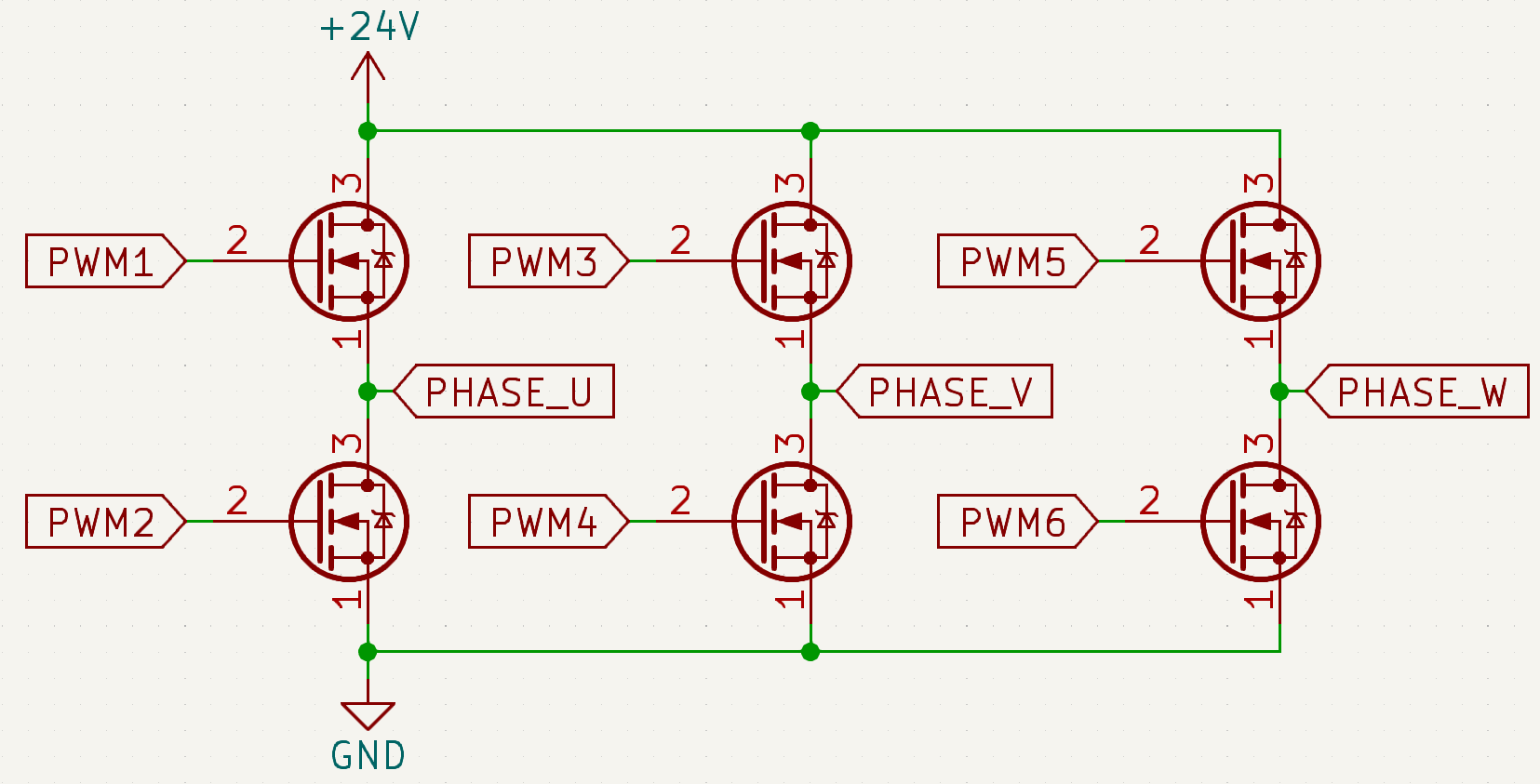
*For example, if PWM1 is ON at 50% duty cycle and PWM2 is OFF (grounded), then PHASE_U is HIGH with an average of 12V because it’s connected to +24V * 50%.
Though this may seem like something you wouldn’t want, (more torque the better right)? It is actually quite important since if the PWM signal’s duty cycle is too high, it would essentially short huge currents (I = V/R) through the motor phases which could damage the motor or the control electronics. It could also lead to unreliable movement if it doesn’t match up well with the desired switching frequency (might pull the rotor too fast, etc.).
*Something that happened on one of this project’s early prototypes.
Now with the general concept understood, let’s move forward with the project schematic!
If you enjoy my work, please consider becoming a free or paid subscriber on my homepage. It helps me keep everything open source and is a great way to stay in the loop.
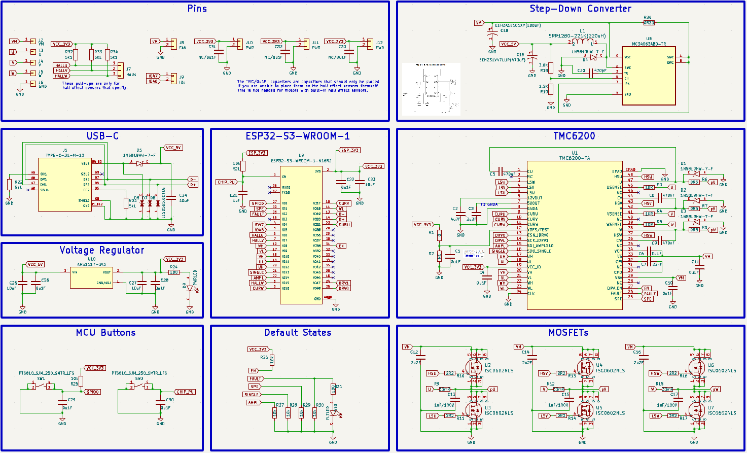
Understanding the Hardware
This circuit consists of an ESP32S3 MCU for primary control and wireless communication, a TMC6200 gate driver for flipping the six MOSFETs (as mentioned), a 24V>5V switch converter, 5V>3.3V voltage regulator, USB-C circuit for flashing the MCU, and some break-out pins for connecting up the hall sensors.
Schematic Download
*Licensed Under Attribution-NonCommercial-ShareAlike 4.0 International: https://github.com/RoboticWorx/ERAD/blob/main/LICENSE.md
The hall effect sensors I used and how to set them up are covered at the end of this section.
Let's dive into a bit more detail.
It should be noted that I won’t explain the microcontroller schematic in this article since I covered it in detail here.
First, we’ll go over the TMC6200 IC since it was the most complex to integrate.
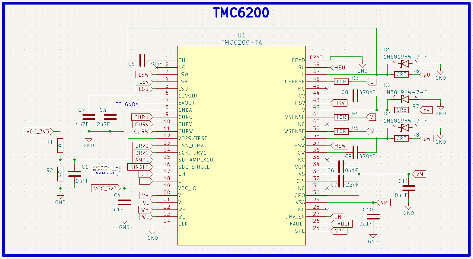
Basically, how I approached this was to first read through the datasheet to get an understanding of the basic functions of the IC. Afterward, I could analyze the Standard Application Circuit to get a general outline of what the circuit might look like.
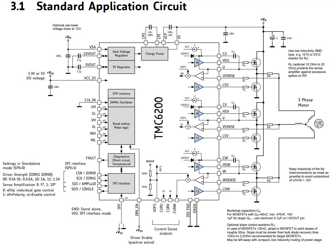
From there, I could also explore the individual pin functions for some more detail on what each one is looking for to properly do its job.
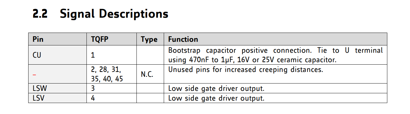
*This table continues down for all the pins.
After that, I read through the datasheet again to ensure I configured everything to the specifications that I needed for my application. For example, I didn’t want to mess with the chip’s SPI, so I ensured everything was set up for standalone mode.
Next, let’s check out the MOSFET setup since that’s related to how the TMC6200 was configured.
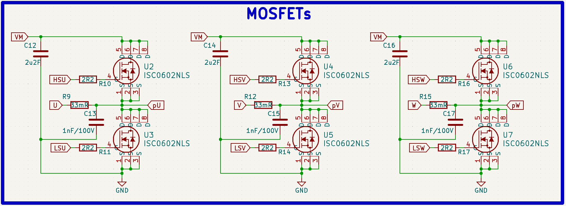
I chose the ISC0602NLSATMA1 MOSFETs for this project primarily because of their low on-resistance and small gate charge. This means that they will heat up less when they are activated and require less current from the TMC6200 to switch (the TMC6200 won’t heat up as much). The gate resistor (2.2 ohms) and the shunt resistor (33 milliohms), were also chosen in coordination with the TMC6200 datasheet as a result of the MOSFET specifications and desired current amplification (should I find the need to measure it later). The 1nF decoupling capacitor was a design choice to ensure a smooth voltage across the motor phases. Now we can move on to the switching converter!
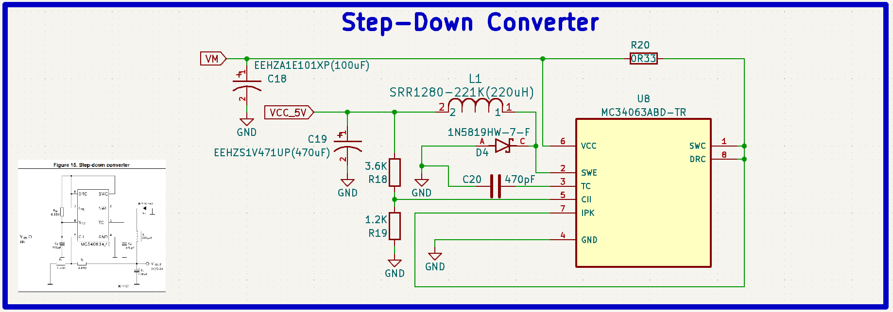
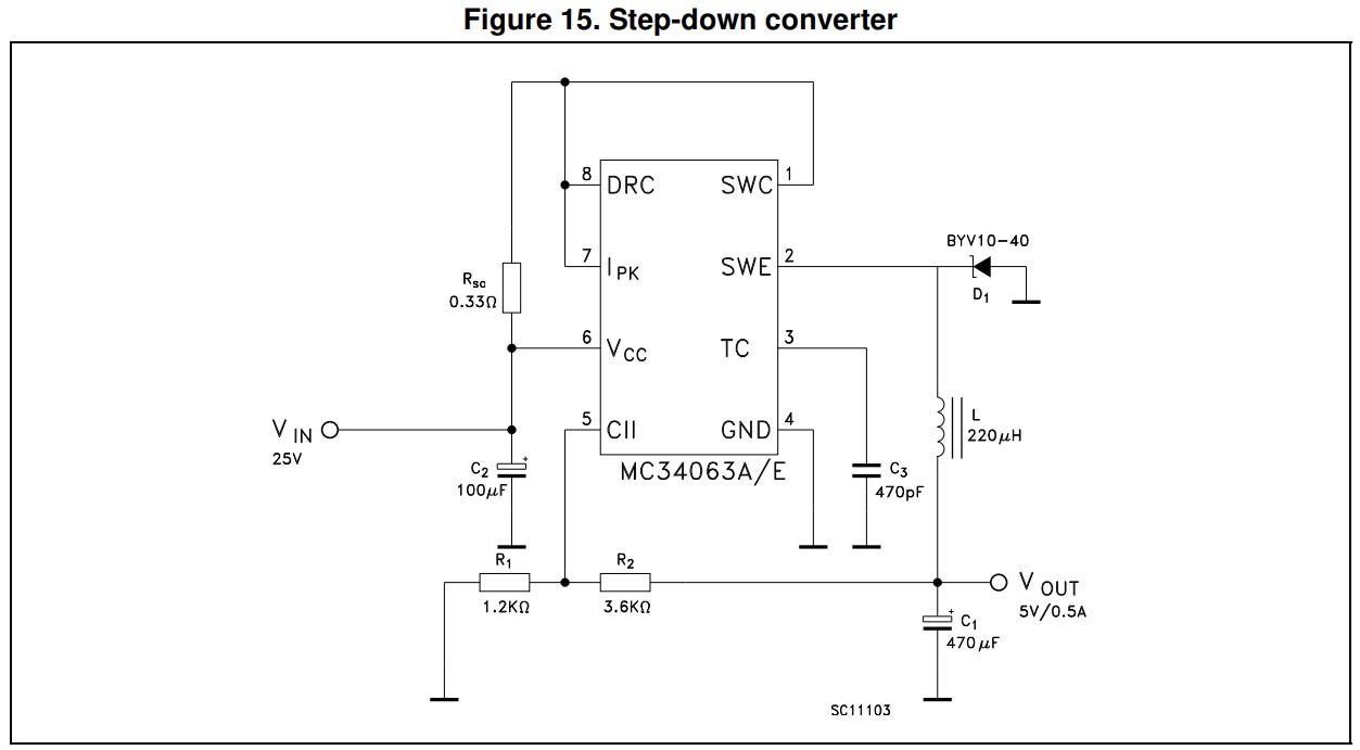
Using a switching converter such as the MC34063ABD for stepping down high voltages is always a great choice compared to something like a huge regulator because of its incredible efficiency.
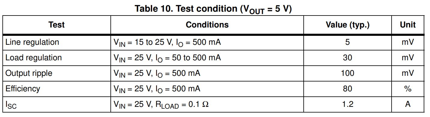
A high efficiency like this means that it will heat up far less in addition to being more energy-conservative. Perfect for a safe step-down. Also, the circuit I needed to step down 24V to a safe 5V was conveniently already drawn out on the datasheet.
*25V is within the acceptable tolerance for this application.
However, if you need to use this IC to obtain a different voltage (say for a future project), there are equations provided on the datasheet to make your calculation. There are even online calculators available to help you out.
NOTE: The reason I didn’t just step the voltage down to a direct 3.3V for the MCU was that I wanted to ensure the current/voltage supply was steady and stable. By nature, converters like this have small ripple voltages, but by including an extra 5V regulator you eliminate any risks and can use cheaper/smaller capacitors.
The last thing I’ll cover in the schematic is the pinout and the hall effect sensors since they were implemented separately. (MCU-related schematic questions were answered here.)
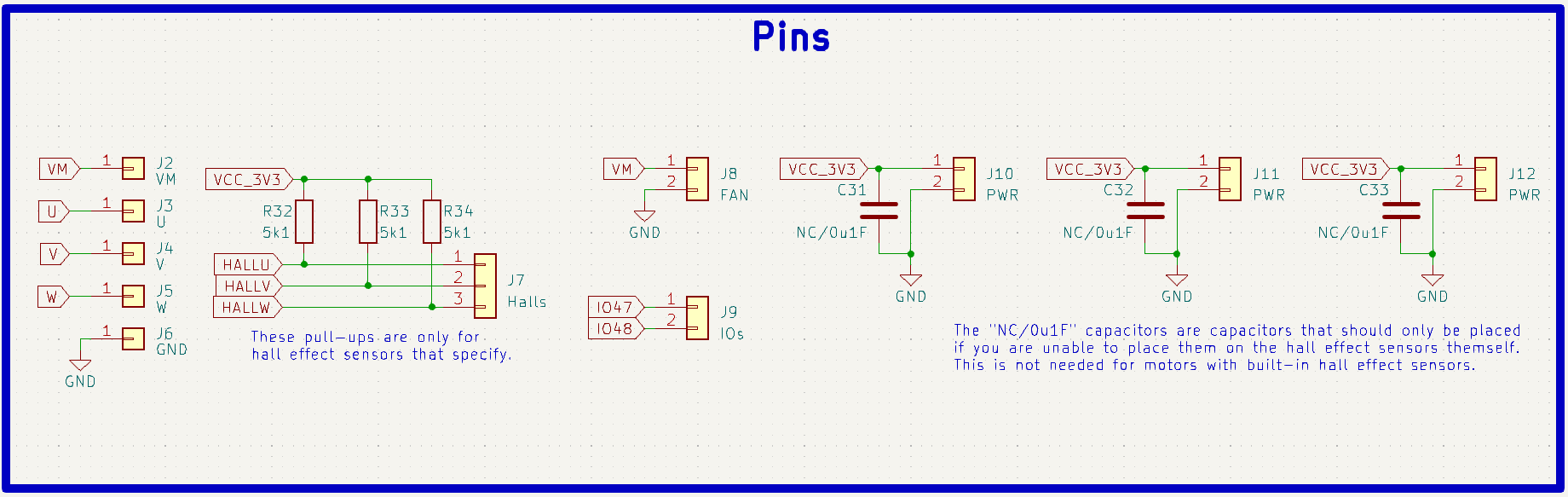
*The “IOs” are just extra pins! Feel free to ignore them.
The five pins all the way to the left are the general-purpose break-out pins to connect power to the board and the motor phases together. The one to the right of that is where you will connect the output of your hall effect sensors. I used DRV5013ADELPGMQ1 hall effect sensors for this. However, it should be noted that the pull-up resistors being used are only for open-drain hall-effect sensors (like mine). If your BLDC motor comes with hall effect sensors and does not use open-drain ones, then you may need to remove them. However, be careful because some of the motors I bought, such as the geared-down one, did end up requiring these pull-ups even though the motor datasheet did not specify it.

The same goes with the 100nF decoupling capacitors, make sure they align with the hall effect sensors that you are using. I’ll go over how to mount the hall effect sensors to an open BLDC motor such as the ML5010 in this section.
It took five full-scale design iterations and a whole lot of time/troubleshooting to get this project right. Prototyping can get quite expensive! Please consider showing your support for these free, open-source projects by becoming a paid subscriber on my homepage. You will also receive the following benefits!
Building the Board
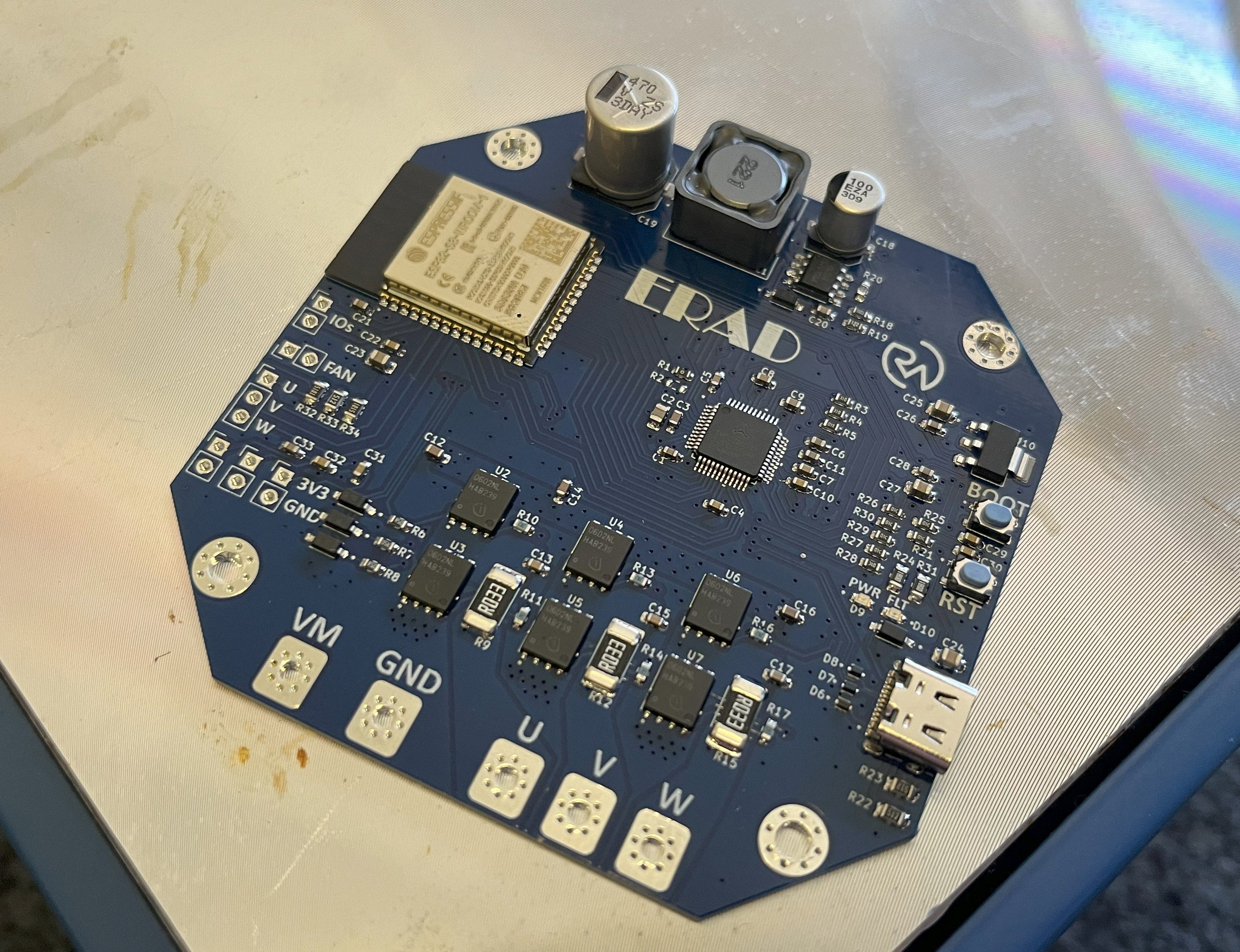
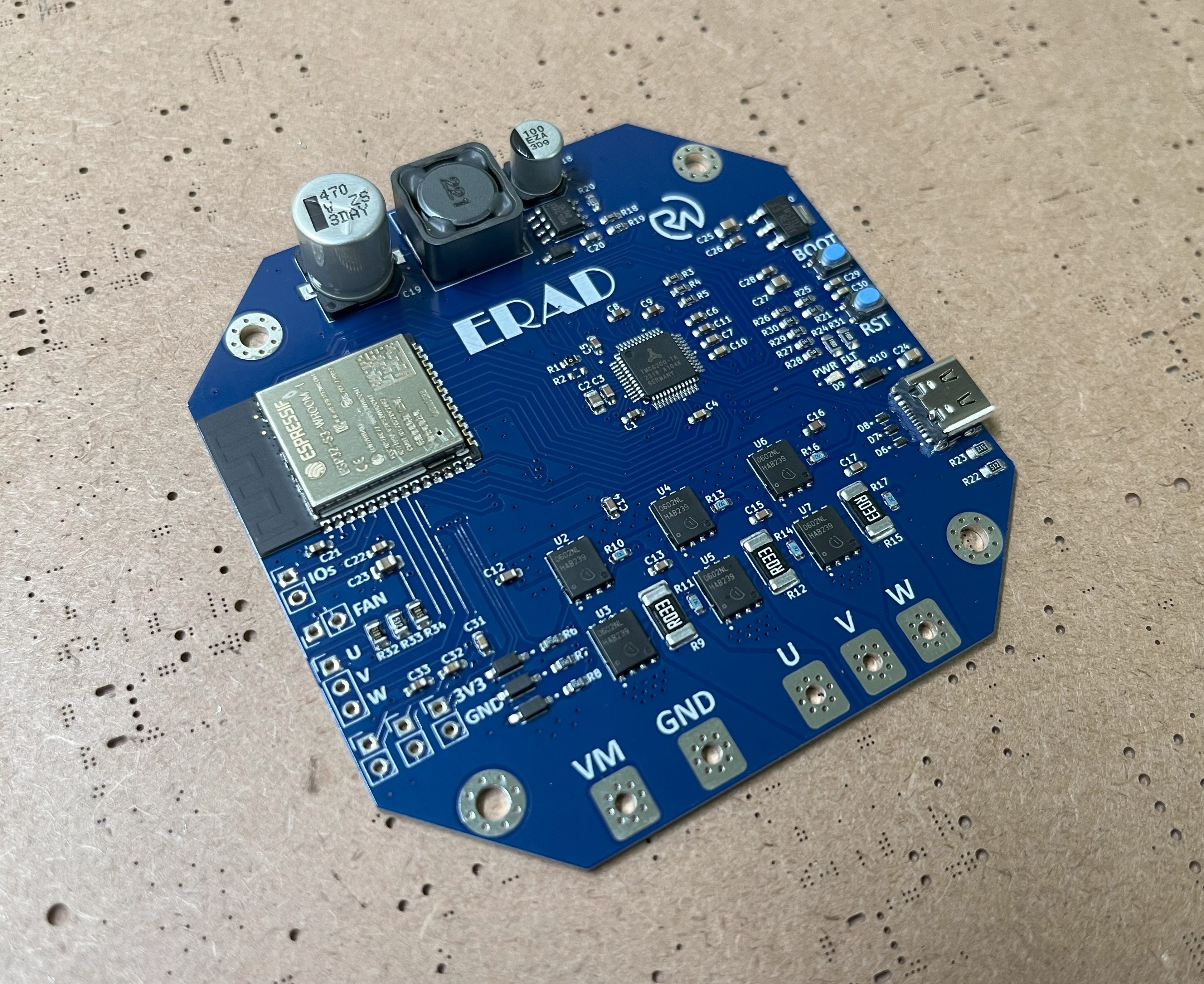
Now let’s check out how to assemble the PCB (Printed Circuit Board)!
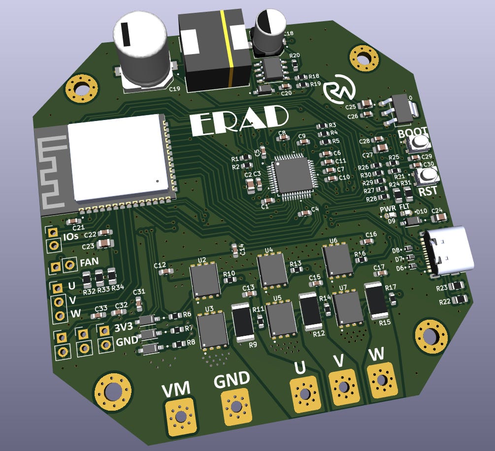
This is a four-layer PCB, mainly focused on efficient thermal distribution. This is why there is a lot of empty space on the board. It allows for a greater surface area to dissipate any heat that the SMDs (Surface Mount Devices) will create.
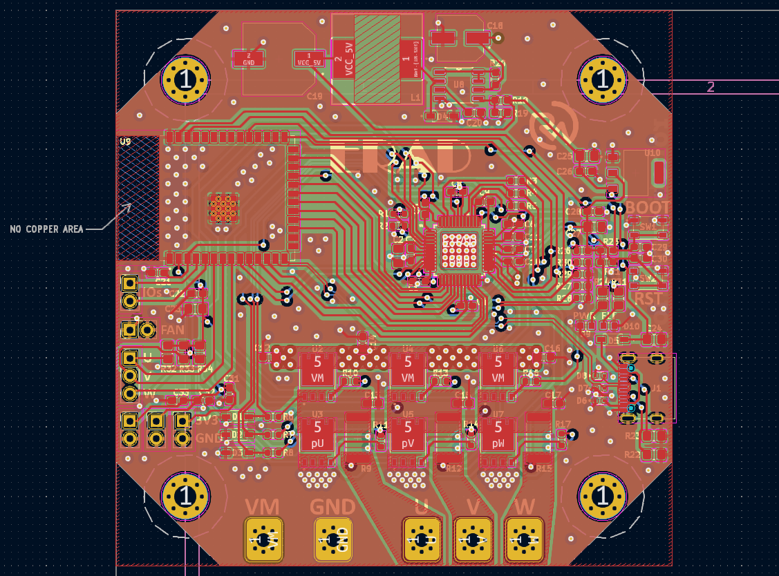
- The Gerber/fabrication file for the board can be found here (click “download raw”).
- Editable KiCad PCB files are available here to paid subscribers. Want to become a paid subscriber? It’s only $5 and I would really appreciate your support!
- The part list for the PCB can be found here with the placement sheet available here.
- As always, I know that it can seem like a pain to have to order parts but it’s really not so bad as the majority of parts that you order for one project end up getting reused. Think about how much you’ll learn with some hands-on experience!
If you’re interested in learning more about PCB layouts and routing, check out Robert Feranec and Phil’s Lab on YouTube. They’re great designers and I’ve learned a lot from them. I also explained a lot about how I route my PCBs in my MCU article.
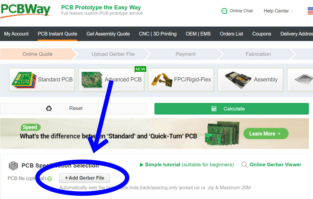
Now all we need to do is get the board made. A perfect job for my go-to PCB manufacturer, PCBWay!

PCBWay always provides fast and reliable PCB services, in addition to others such as 3D printing and CNC machining. Since I designed with KiCad, I didn't even have to leave my design software to check out thanks to their convenient plug-in! If not though, you can always just go to PCBWay.com, click on quick-order PCB, and upload the Gerber file for the board. Or alternatively, just go here which I have saved in my favorites bar. I recommend clicking the stencil option at checkout to make assembly easier!

You can pick any color you want!

![]()
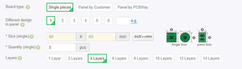
All other settings are default.
If you’re asked about the stack-up, you can just fill it out like so:

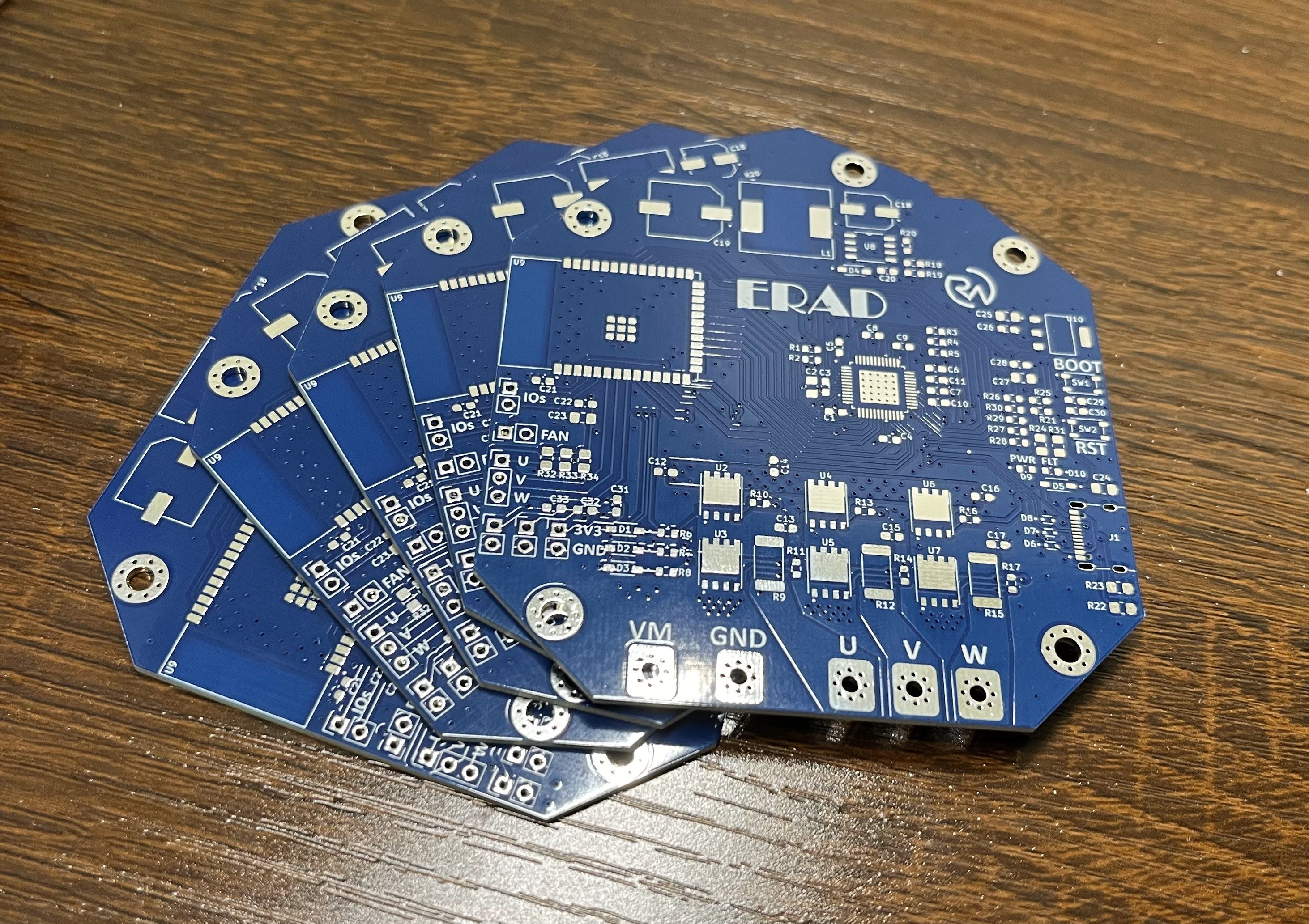
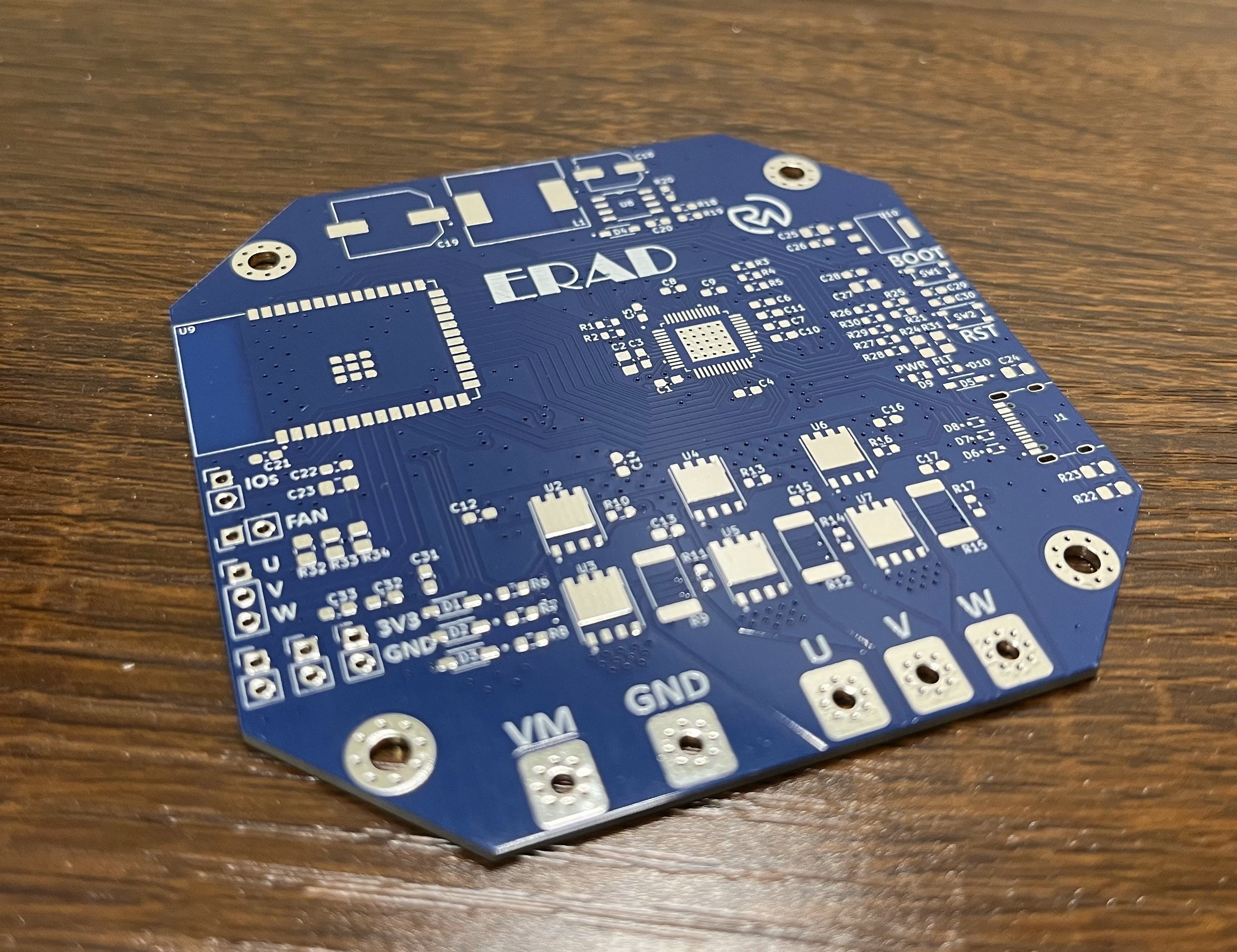
As always, when the boards arrived they looked amazing!
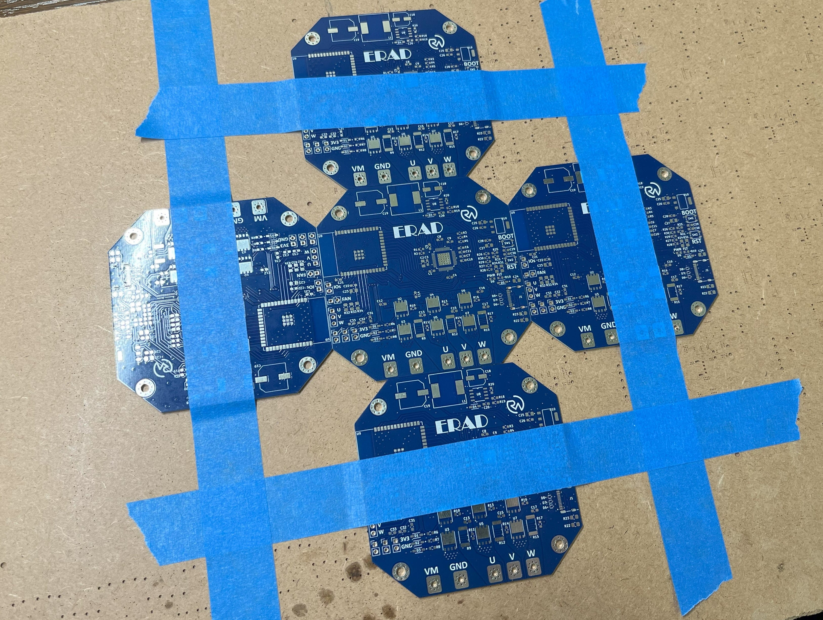
Now let’s assemble it! First, you’ll want to suspend the PCB in place with some tape and your other boards.
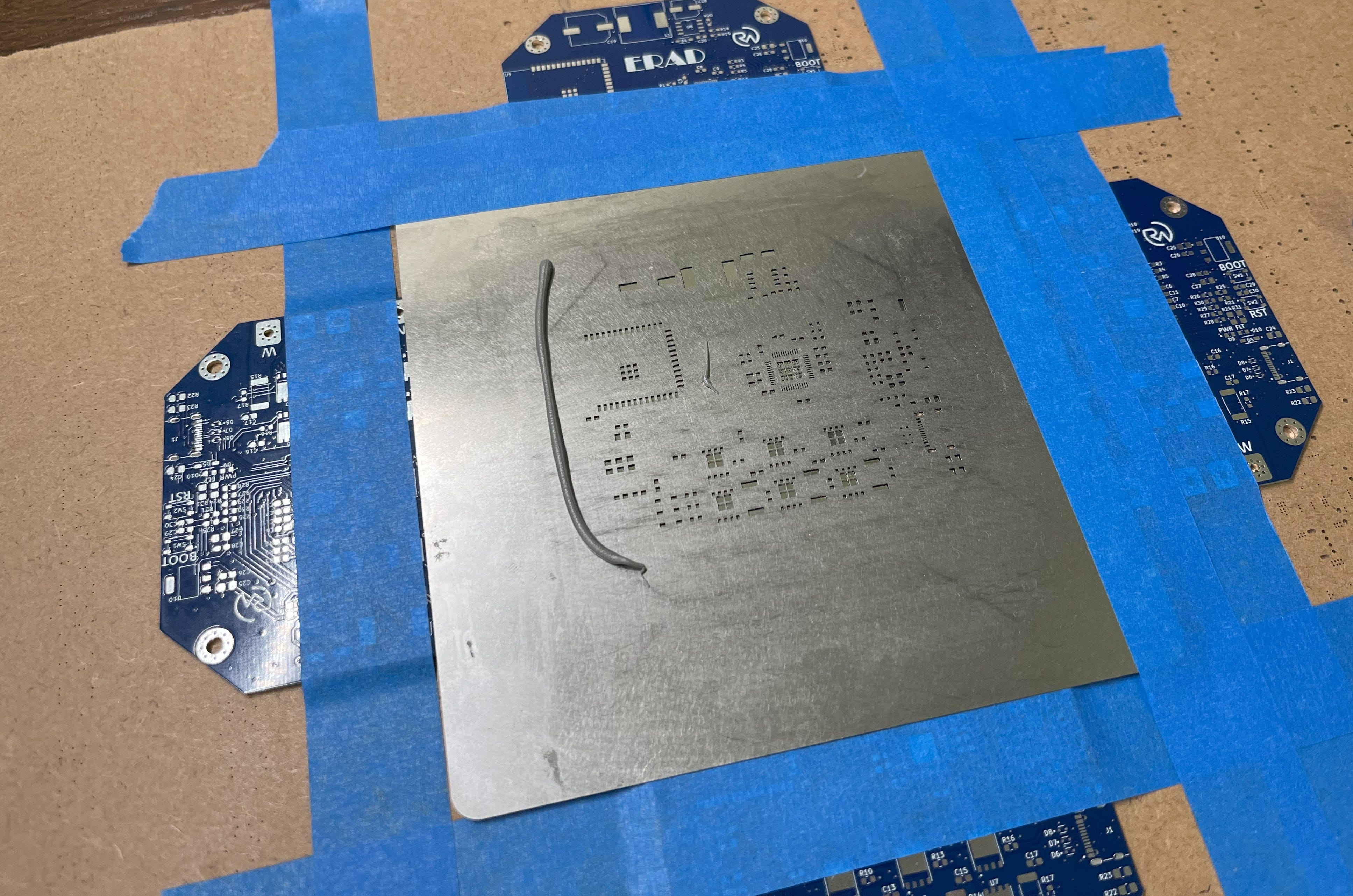
Then, you can tape your stencil over it and apply a line of solder paste.
From there, you can go ahead and spread the solder paste over the stencil. I used a stencil spreader for this but something like a 3D printer scraper also works great.
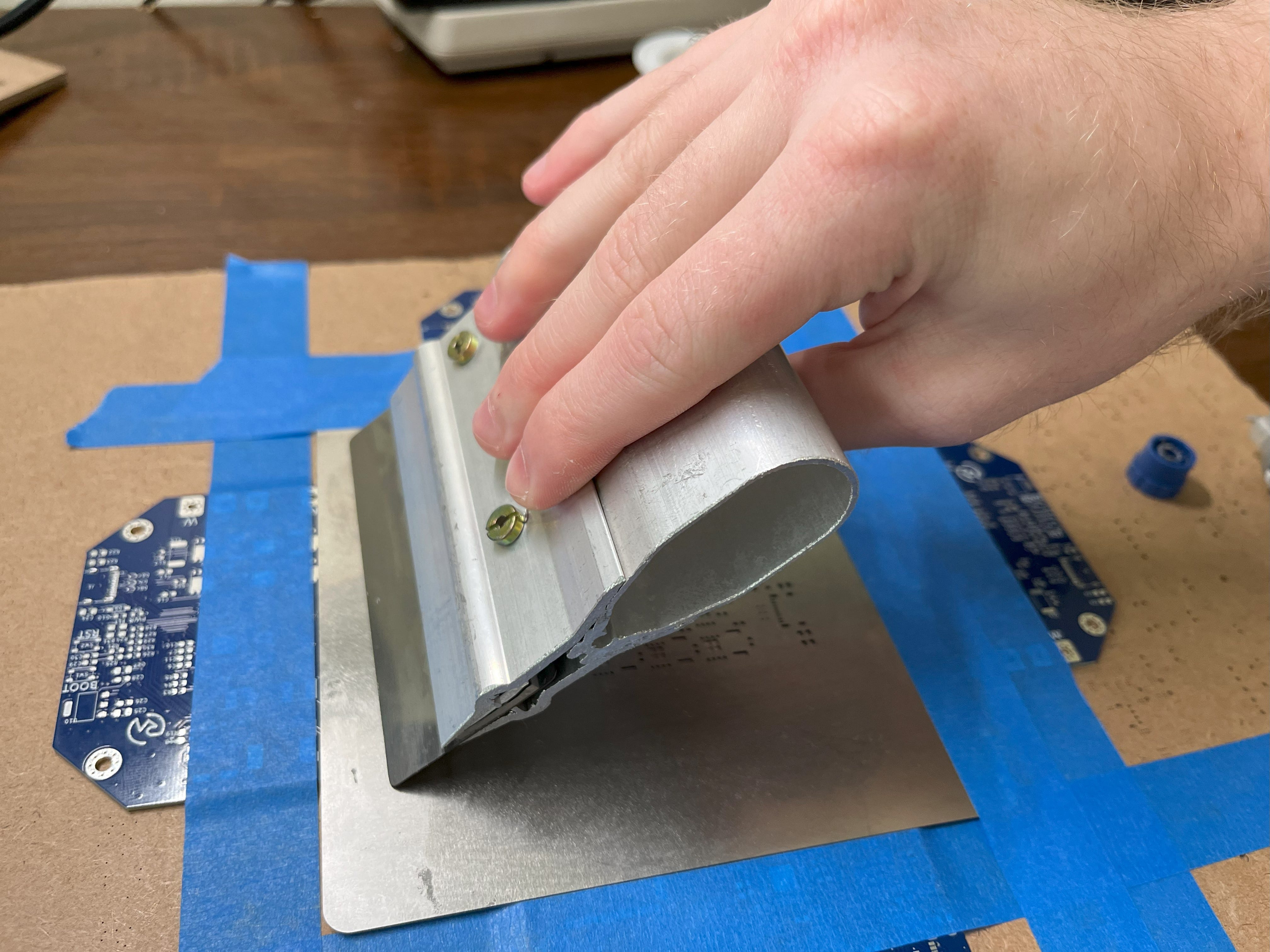
Perfecto!
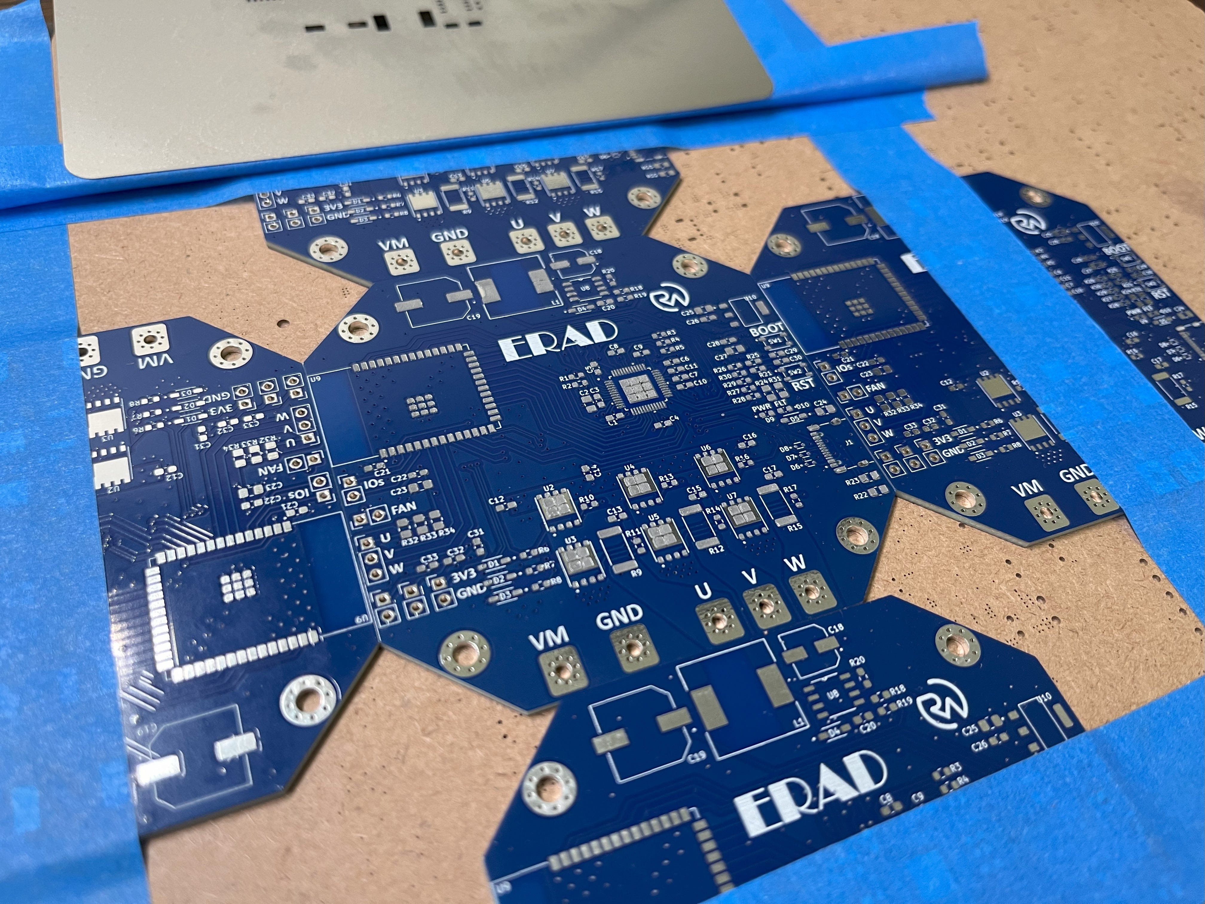
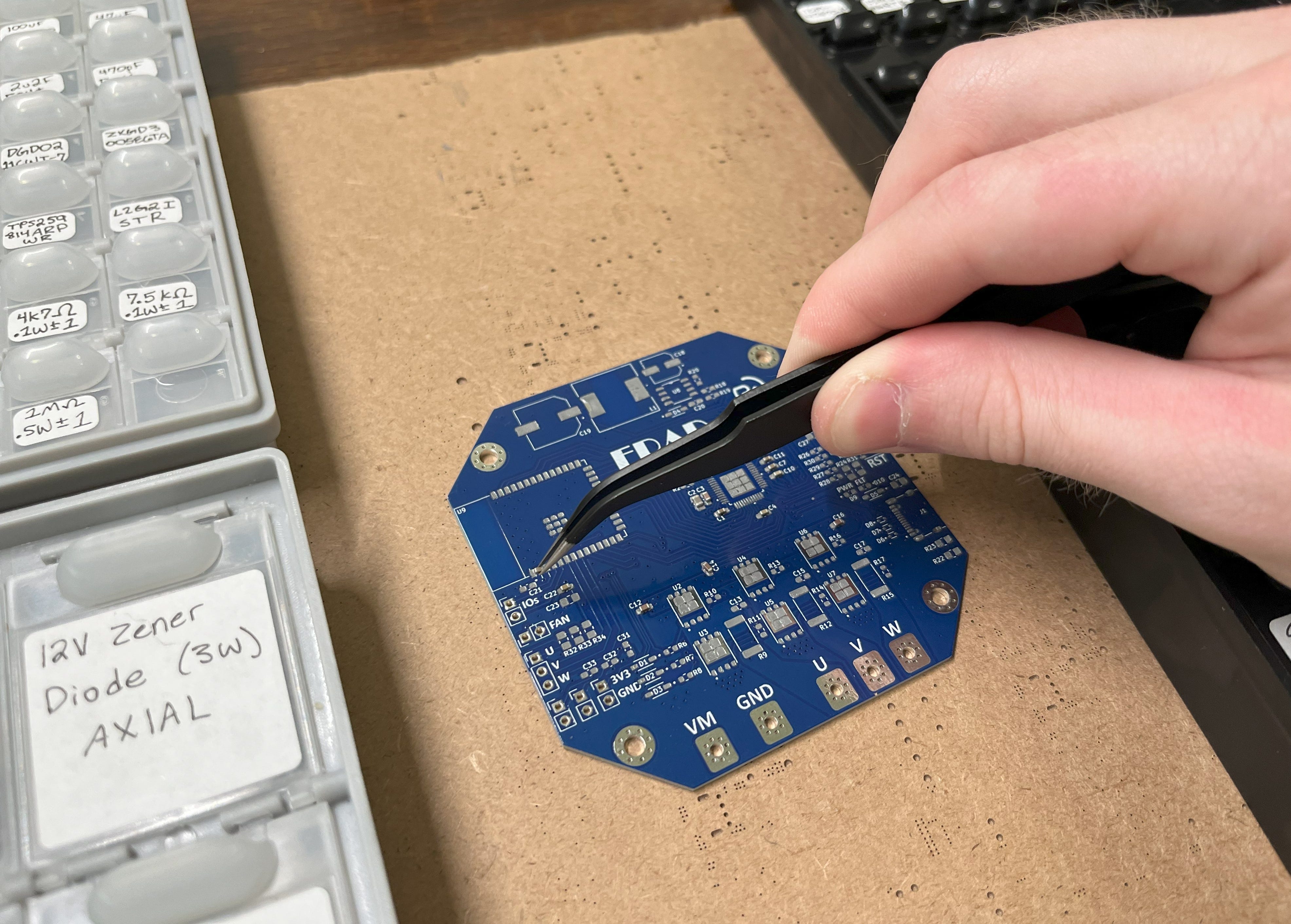
Now you can carefully take it out and start placing the SMDs in coordination with the placement sheet.
With that done, it’s time to melt the solder paste by placing the board on a hotplate (or by using a heat gun).
*I like to let mine heat up to ~225C before removing it.
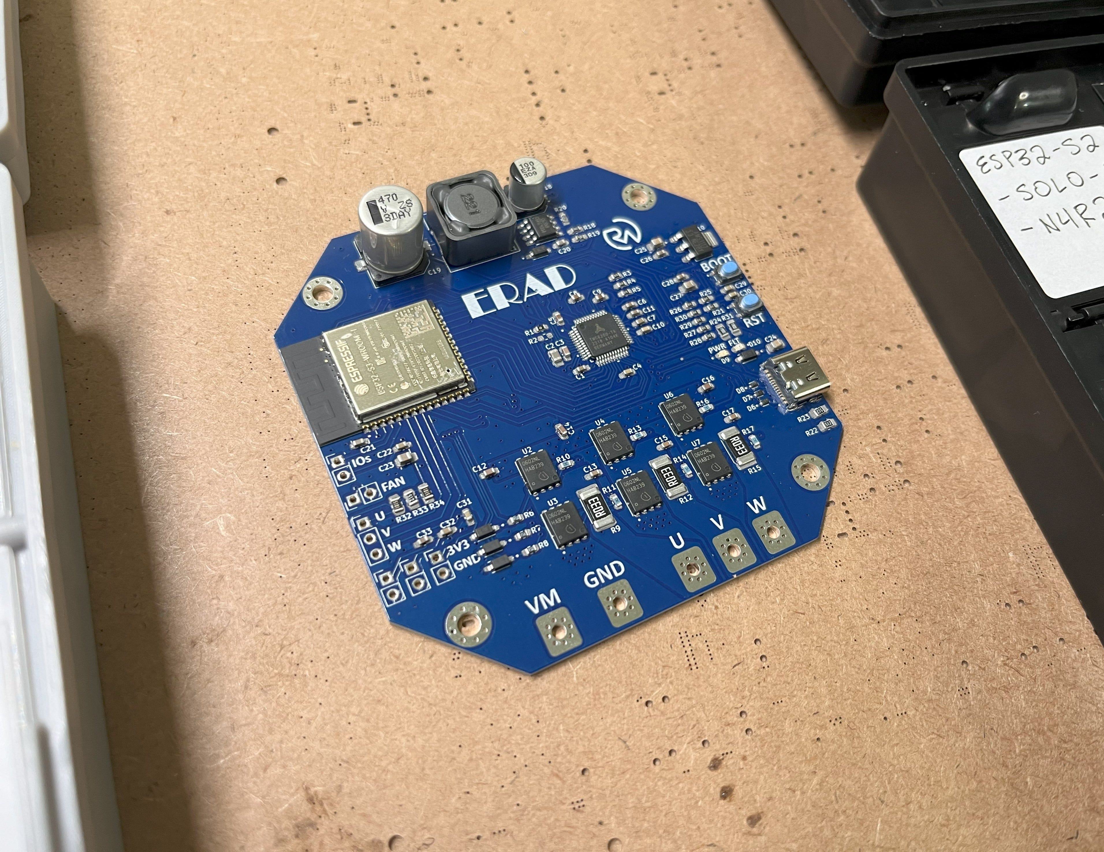
When the solder paste is melted, you can remove the board. Then, voilà! A beautifully assembled PCB.
Mounting the Hall Effect Sensors
This is a very important step in setting up your BLDC motor. You would have pretty much no torque without these (assuming no back EMF implementation), so let me show you what I’ve learned.
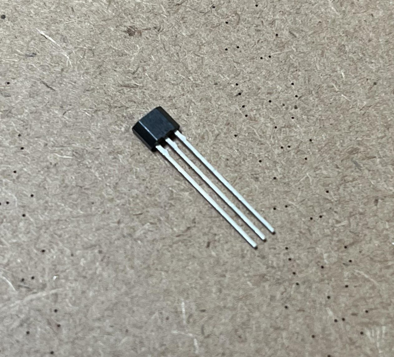
*A DRV5013 hall effect sensor!
Basically, there are a few ways to do this. The first way is to ensure that each effect sensor is placed 120 electrical degrees apart, sequentially. This is NOT the same as mechanical degrees, which is what you probably first think of when hearing degrees. An electrical degree is a unit of measurement based on the number of poles that a motor has. The electrical angle (120 electrical degrees) can be calculated as follows:
(2 / number of poles) × 120
But what are poles? Poles are the permanent north and south magnets that attract or repel the coils of the stator. The number of pole pairs (which you’ll need to know later) is the number of poles (magnets) divided by two. For example, an ML5010 motor (below) has 14 poles and 7 pole pairs (14/2).
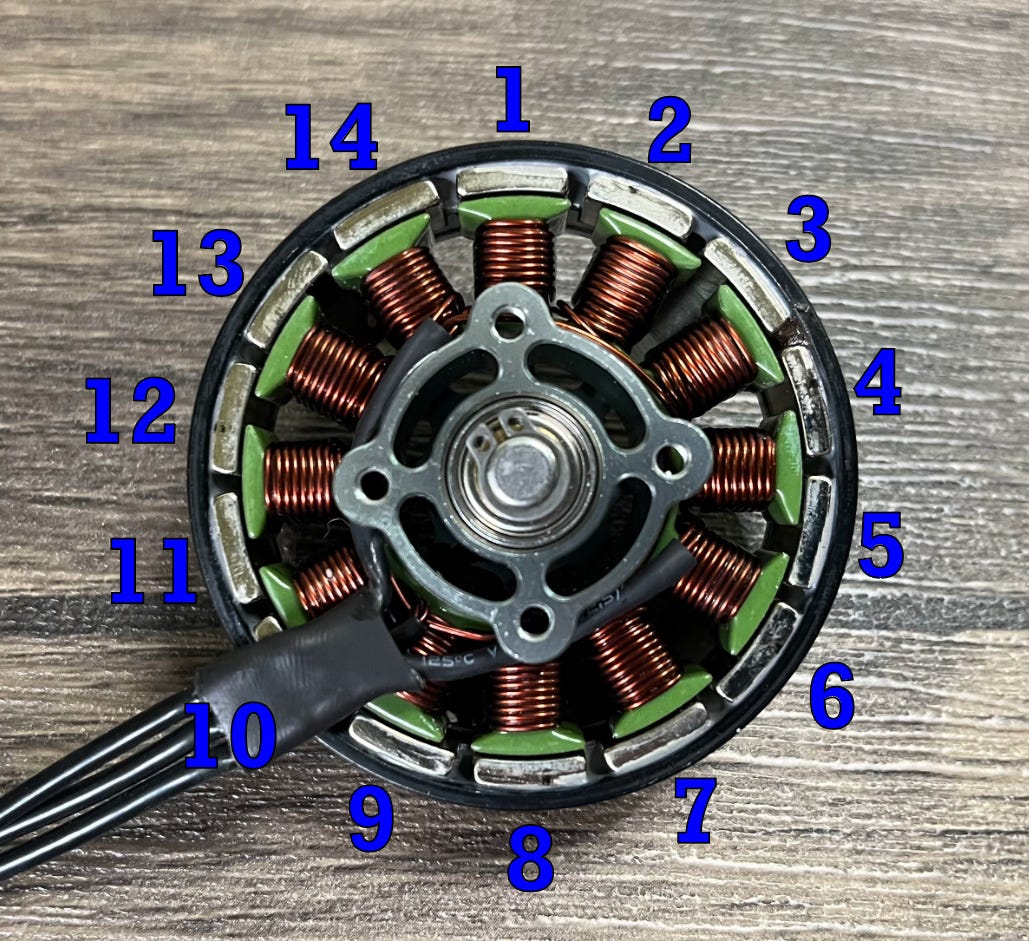
So if we wanted to calculate the hall effect sensor spacing for this motor, we would get 17.14 mechanical degrees per electrical angle (sensor). Now, you may have noticed an issue. It would be pretty hard to perfectly space out 17.14 degrees for each sensor, and there would also be windings in the way! How can we solve this? I’ve found it best to make a table.
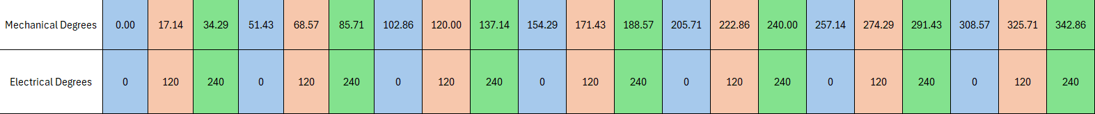
This is a bit hard to see, so let me enhance it some.


The top row is in mechanical degrees, and the bottom is in electrical degrees. I’ve notated each electrical angle (every 120 electrical degrees) in a different color to help distinguish them. What’s important when mounting the hall effect sensors is that each one covers a different phase (color). This means that mounting the sensors at 0, 17.14, and 34.29 degrees is essentially the same as mounting the sensors at 0, 120, and 240 degrees (equal spacing) which is way easier to do. The same goes for any other combination in which all three are at a position with a different color. This is because even at a different mechanical position, each is offset the same 120 electrical degrees relative to the last. Pretty neat!
This also means that mounting the hall effect sensors at 0, 120, and 240 degrees (equal spacing) should work for just about every standard BLDC motor. Convenient!
So, if we wanted to mount some hall effect sensors to an ML5010 (for example), even spacing would do just fine. I find it best to use super glue.
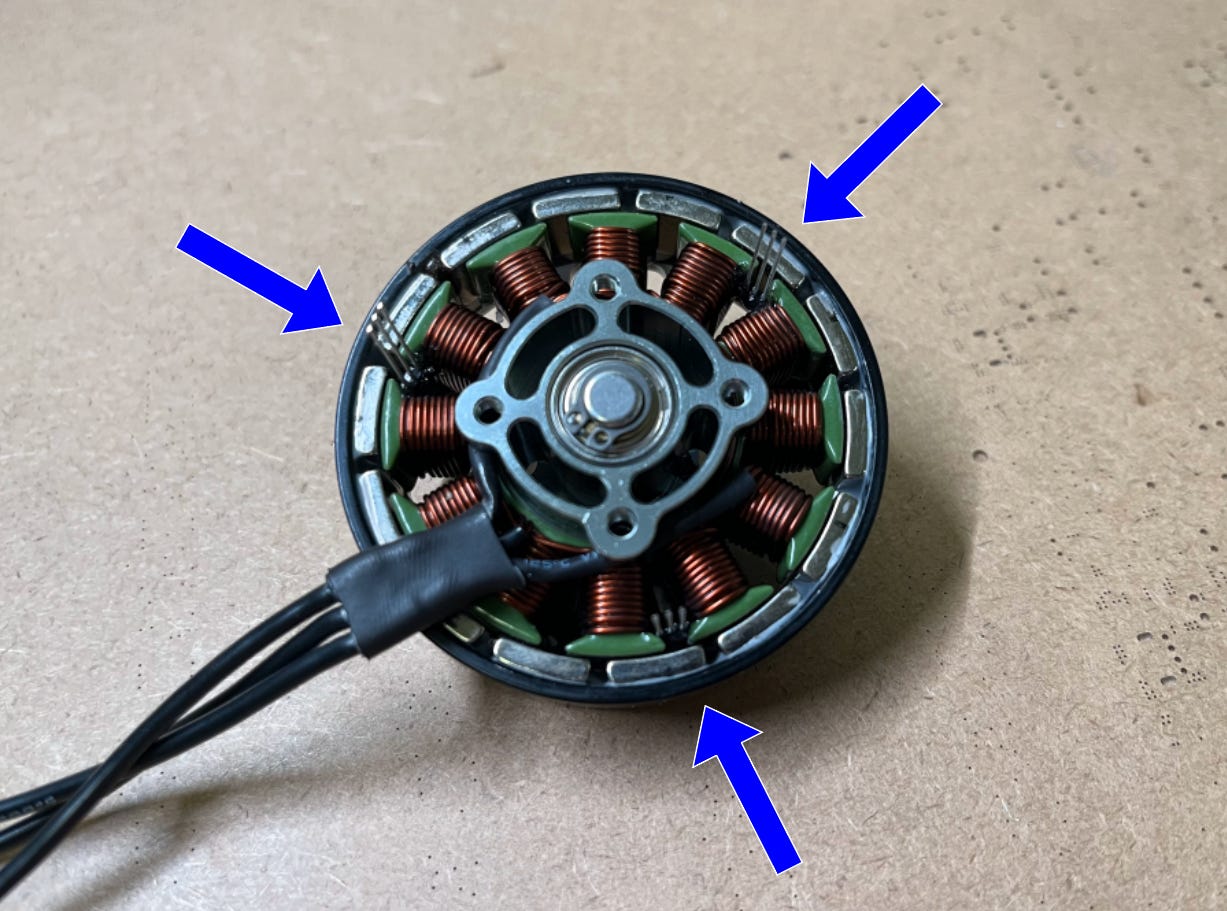
Important note: Make sure the flat side of the DRV5013 is facing the center of the motor (the chamfered side is pointing out) when mounting. Otherwise, you may have some problems reading the magnet polarity.
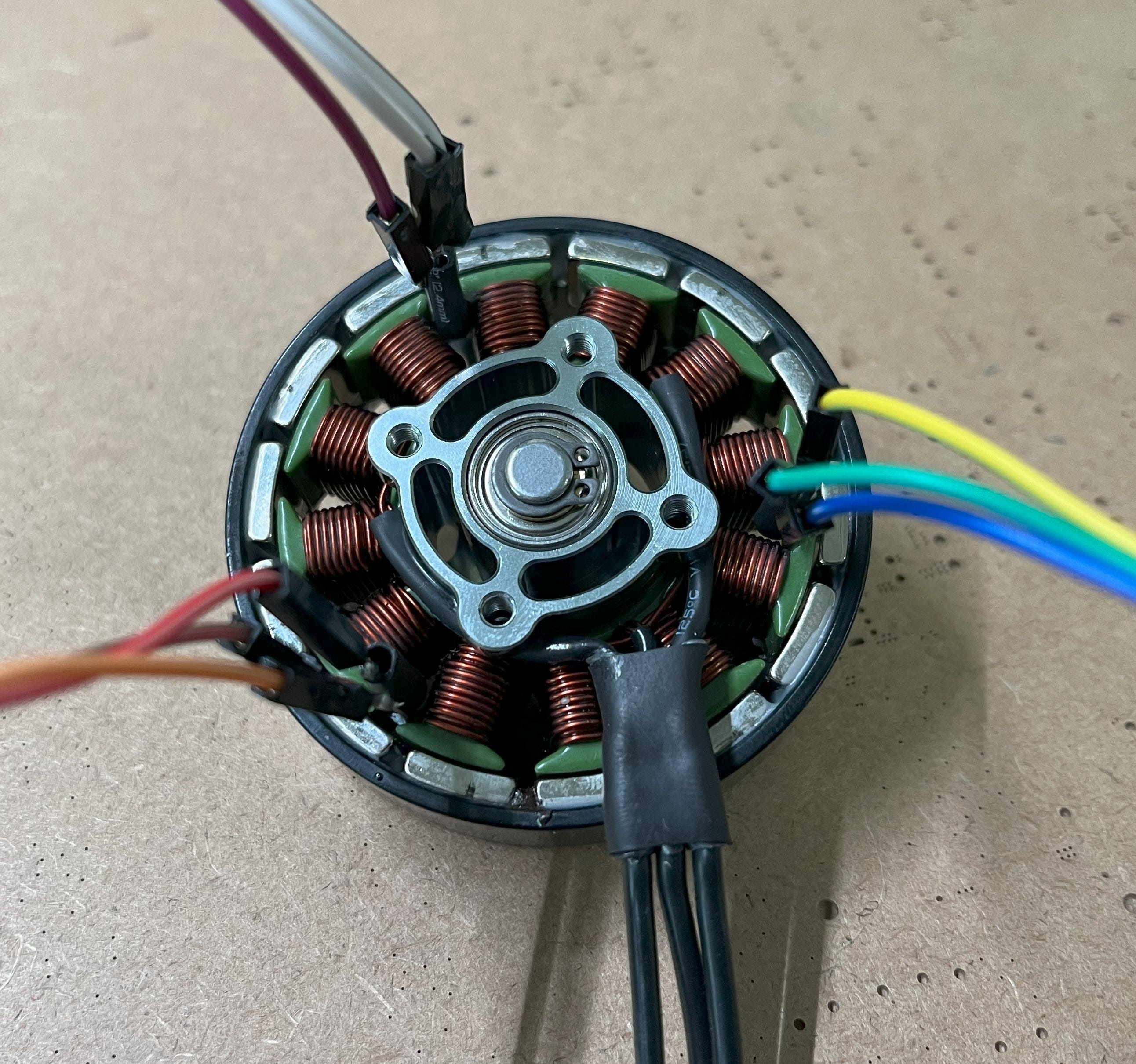
After the glue has cured, you can solder some wires to them. I also placed a piece of heat shrink over each middle pin to ensure they wouldn’t short to each other.
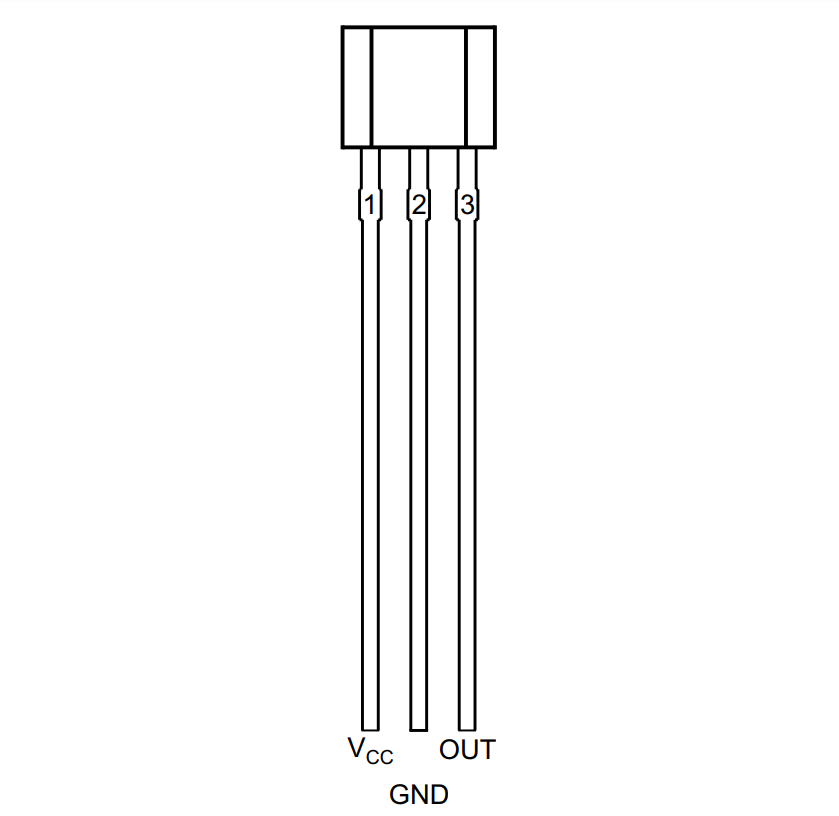
*Pin definitions^
With that, the mounting is done!
I should also point out that if for any reason you need to use 5V-rated hall effect sensors (such as some in pre-mounted BLDC motors), ERAD can still utilize them by wiring up a 5V→3.3V voltage divider directly from the regulator. For example, the geared BLDC motor I’m using uses SS41F-series hall effect sensors which require 4.5V-24V for supply and switching. I can take the 5V supply directly from the onboard regulator and solder up a quick voltage divider to make it compatible with the 3.3V logic on ERAD.
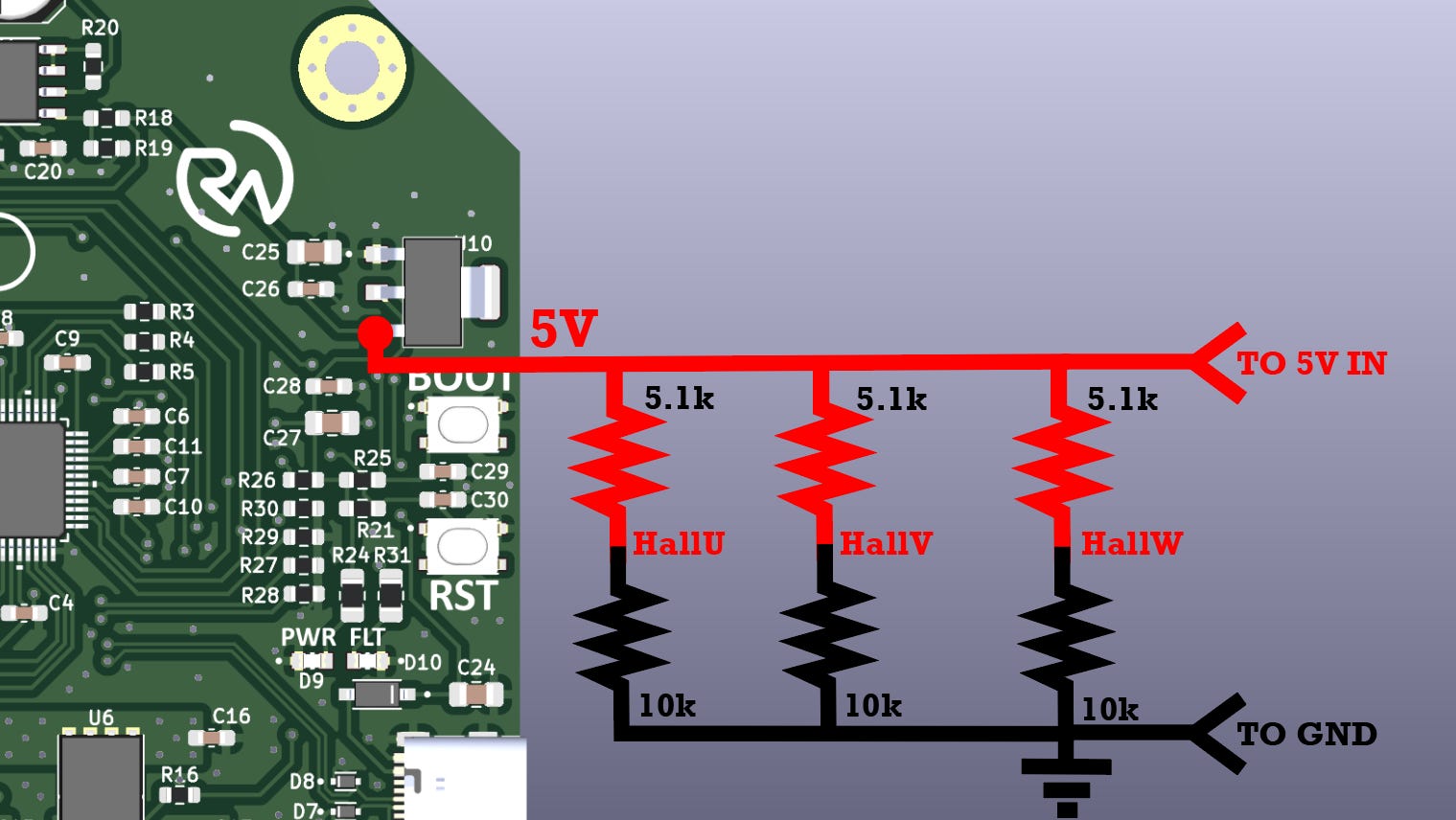
*“TO 5V IN” and “TO GND” refer to the power inputs on the pre-mounted BLDC motor.
Then, I can just connect the hall effect sensor outputs from the motor to each corresponding spot between the two resistors and another wire from that same spot to each phase input on the PCB (U, V, W).
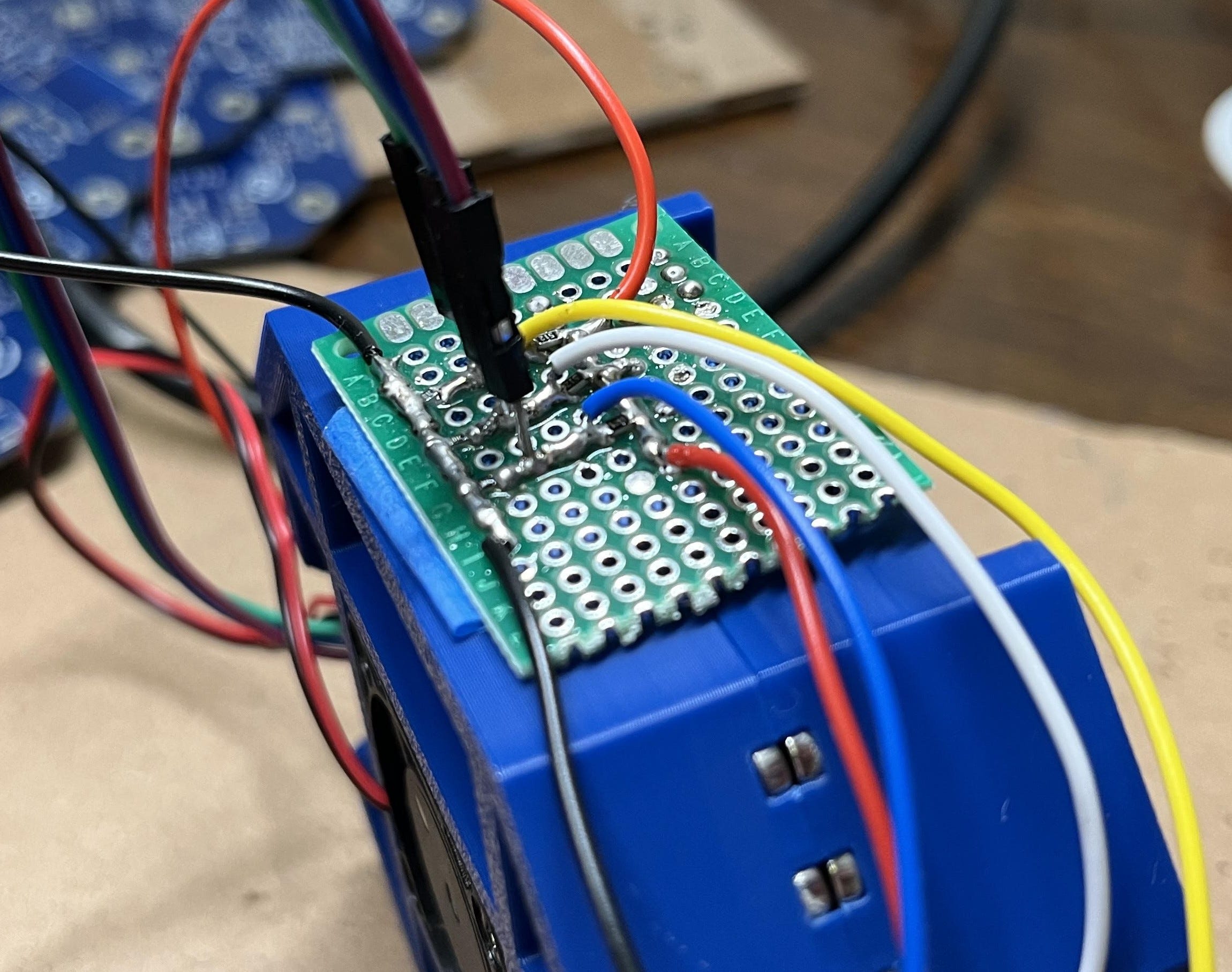
*A protoboard that I made for this using SMD resistors. Make sure to use a common ground!
Done! This also works if you need 24V by wiring it directly to VM. Just be sure to update the voltage divider resistors. Here’s a helpful online tool/calculator if you’re unsure about what values.
Assembly
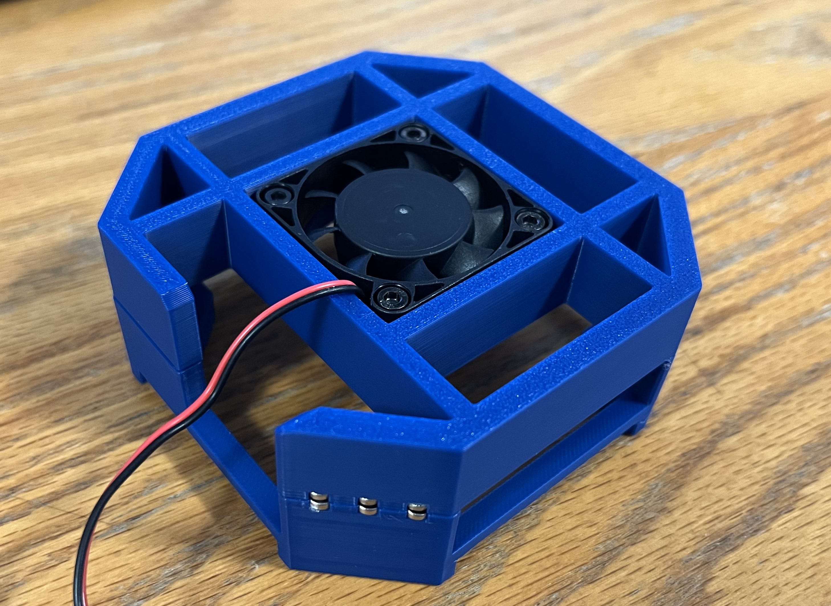
Now let’s assemble the airflow casing! This is not required but is nice to have since it’ll keep a cool flow of air over the PCB to prevent it from getting too hot under extended use.
Note: The free download has a logo! If you’re interested in downloading the logo-less version in addition to the editable STEP files, please consider supporting me by becoming a paid subscriber for $5!
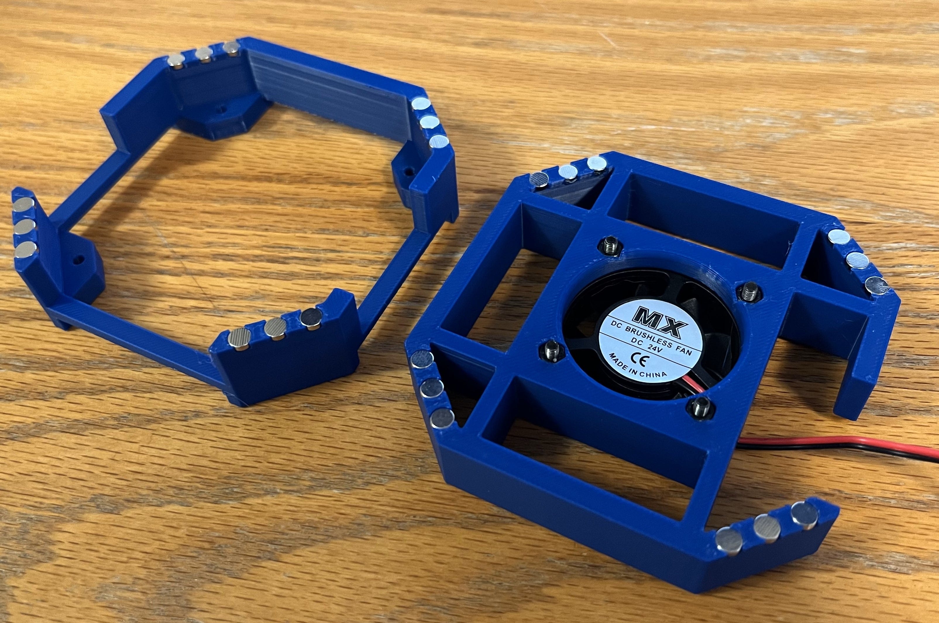
First, grab the top piece and pop some M3 nuts in the four hexes on the bottom. Then screw in the cooling fan using some M3x16mm bolts.

Next, grab the bottom casing and insert some more M3 nuts into the other four empty hexes on the piece.
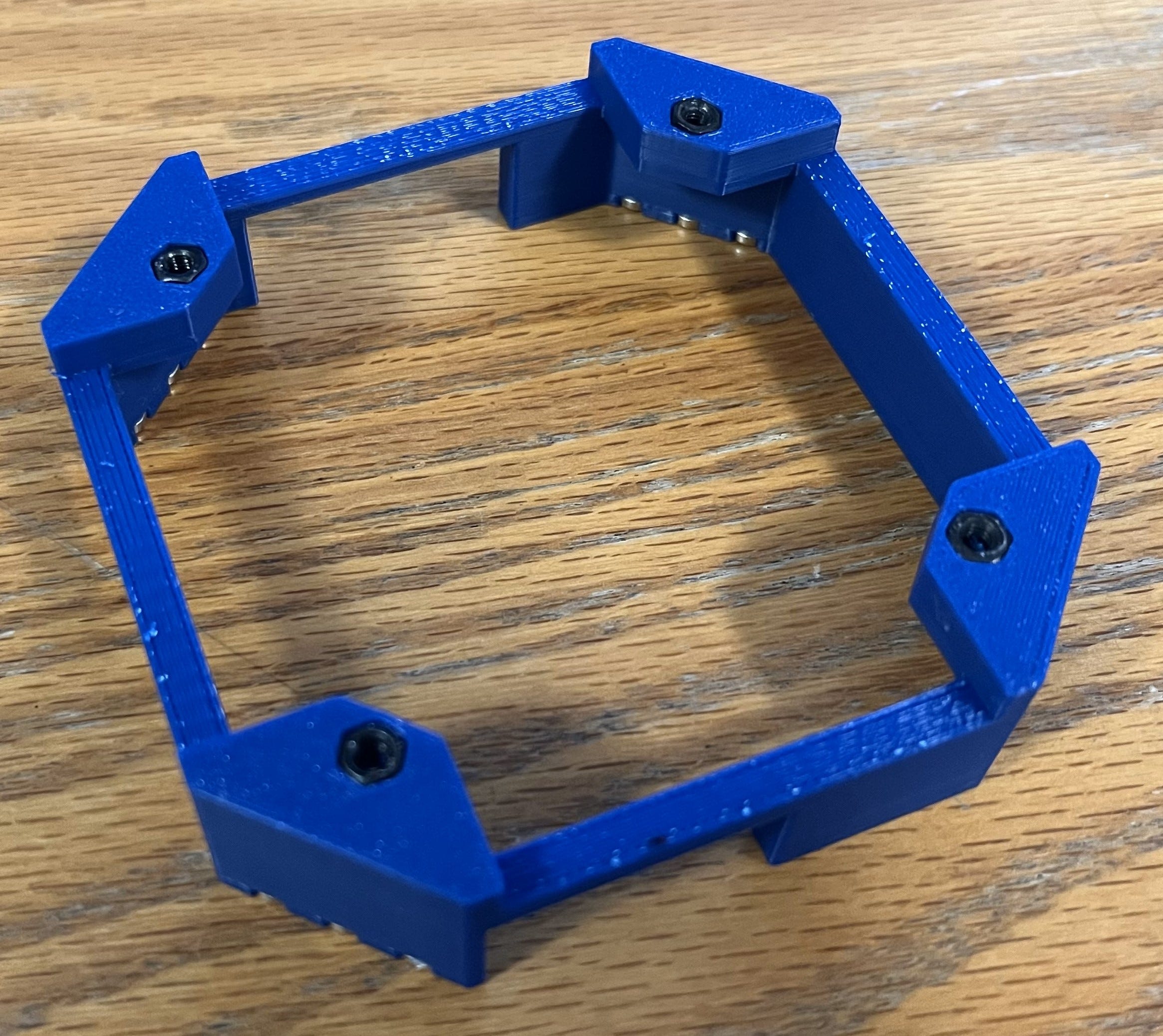
Then, pop in some 5x2mm Neodymium magnets. I recommend dabbing on some superglue before pushing them in! Don’t worry, the magnet’s polarity doesn’t matter at the moment.
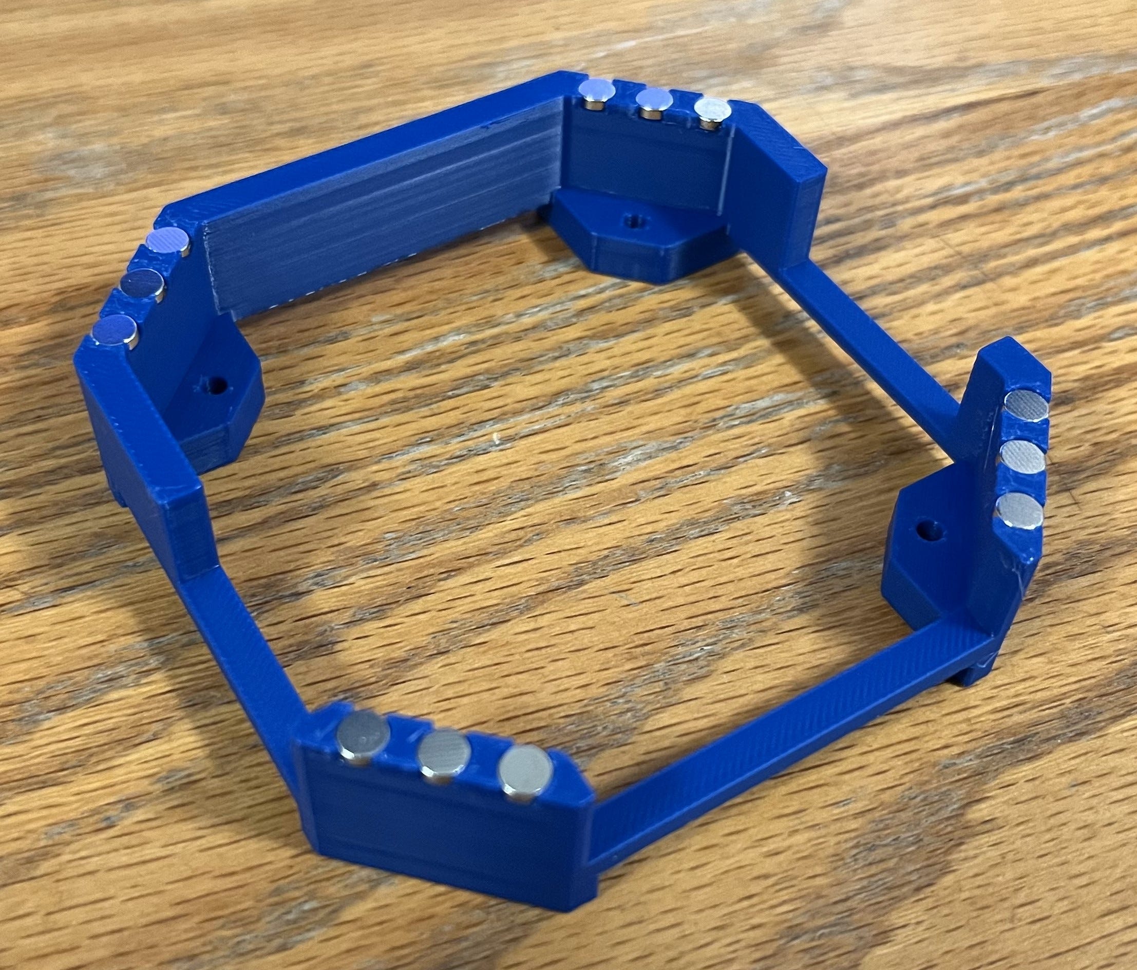
After that, grab some more magnets and let them flop over each one that’s already mounted. Then, grab a Sharpie or another writing utensil and distinctly mark the top of each magnet.
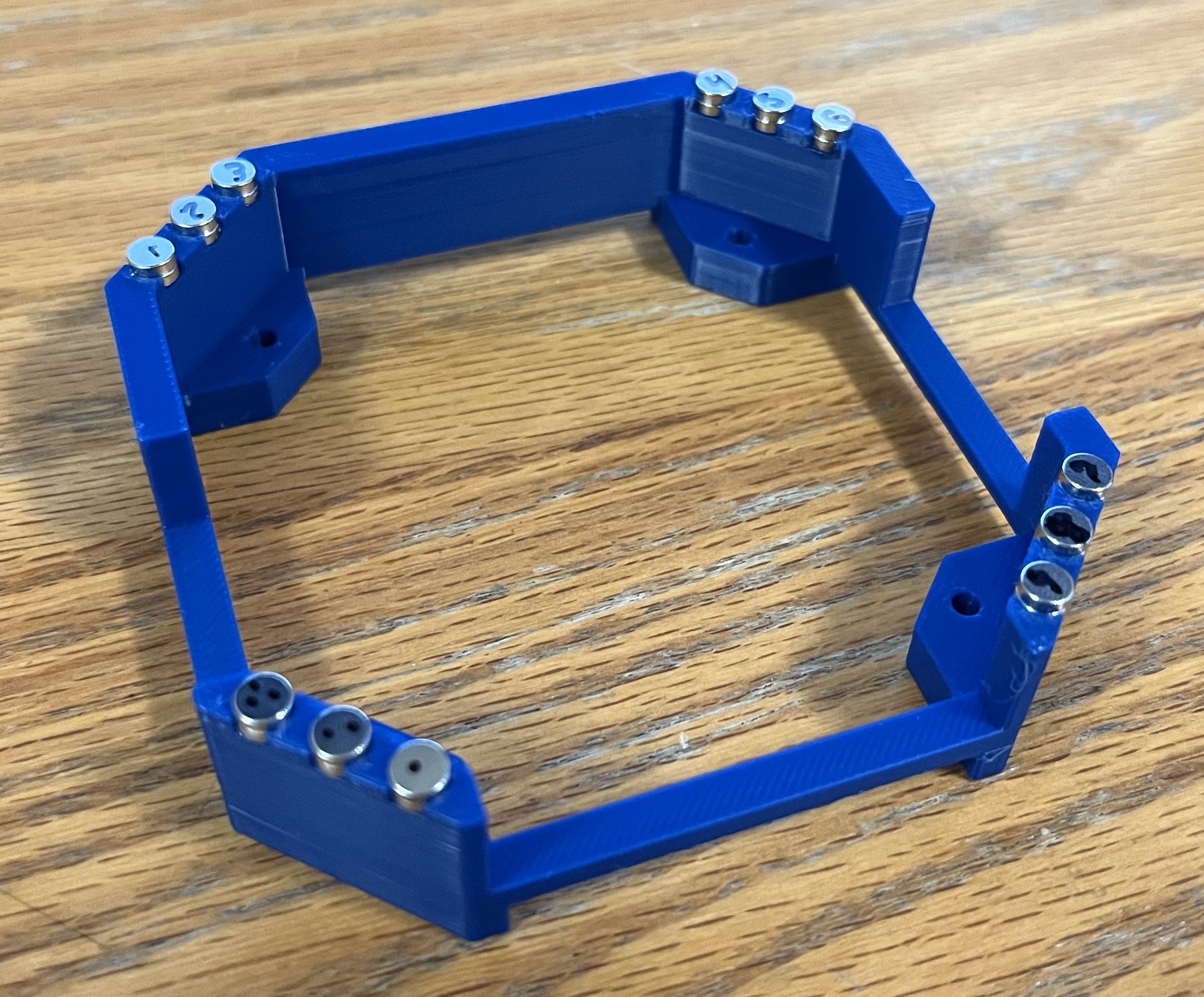
Next, grab your original top piece and mount the magnets with the same method as before. The notation ink should be facing down in a mirrored orientation from the last so that each magnet attracts to its pair when the pieces are placed on top of each other.
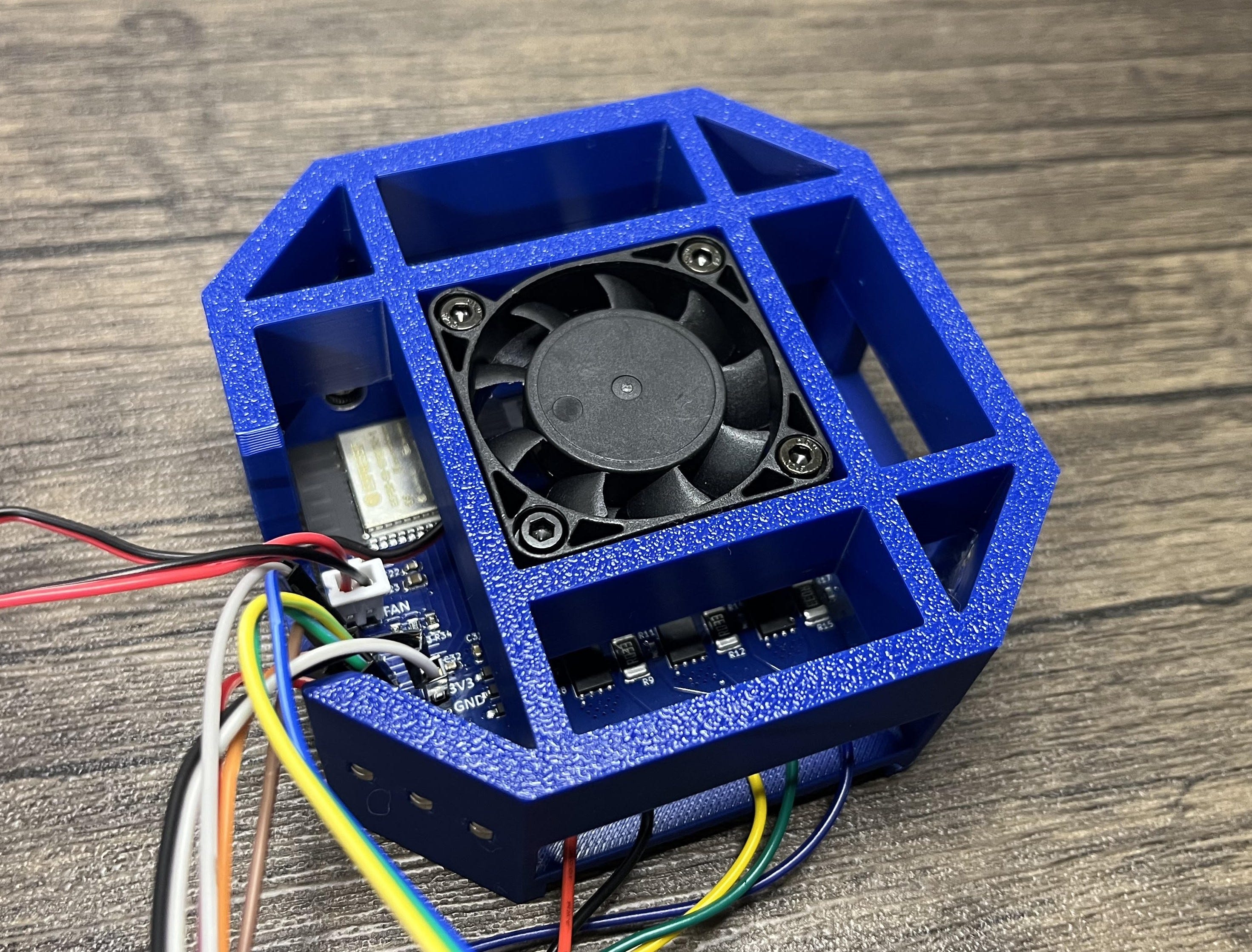
When the glue dries, you can give it a test! If all goes well it should be super satisfying.

Then, you can screw in the board with some M3 bolts, plug in the fan, and you’re done!

Programming
Let’s walk through how to set up the default program for controlling our custom BLDC motor driver. As I mentioned earlier, the BLDC is controlled using the SimpleFOC library on the Arduino IDE with wireless communication handled by ESP-NOW.
If you need some help setting up ESP32 on the Arduino IDE, I explained it here.
NOTE: Before uploading any code, you must put the board into bootloader mode. You can do this by holding the boot button > hitting the reset button (RST) > and then releasing the boot button.
Let’s get started!
- The complete test code for the ERAD PCB can be found here.
- Some example code for the transmitter can be found here.
I should also point out that these are starting point programs for basic functionality. All this code will do is wirelessly move the BLDC motor at a speed determined by the rotation of the sender’s potentiometer. If you would like to learn more so you can implement custom functionalities for any specific application, these SimpleFOC example programs are an awesome reference.
Here’s a breakdown of how the basic ERAD-SimpleFOC program works:
First, we need to include the libraries we are using and define the pins we have connected.
After that, we need to create a data structure to hold the received wireless data as well as set up the ESP-NOW callback function. This function will be called whenever data is received.
Next, we can create an object for the BLDC motor and driver. ERAD uses a six PWM signal control scheme, so we need to initialize the driver for 6PWM. I should also point out that you’ll need to update the POLE_PAIRS variable based on the motor you are using. Remember, this will be the number of permanent magnets divided by two.
When that’s done, we can do the same thing for the hall effect sensors.
Now we can just about move on to the setup. I set my max_velocity to 100 as a good starting point but this should be changed depending on what your application requires.
With that, we can set the TMC6200 driver strength to 0.5A/1A by setting the two driver pins. Afterward, we can give the enable pin a quick toggle to reset any fault flags that may have been lingering.
Then, we need to set the device as a WIFI station and initialize ESP-NOW as a receiver.
Next, we can initialize the sensor, driver, and controller. I should also point out that you may need to (and probably should) adjust driver.voltage_power_supply and motor.voltage_sensor_align depending on your application.
We can also set up the PID constants, ramp, and motor. Like the last, motor.voltage_limit will need to be configured based on your needs. However, I’ve found it best to start at a low value so you don’t accidentally break anything, as these variables configure how much power the MOSFETs on the PCB are allowed to switch for the motor phases.
Finally, we move on to the main loop where we can constantly map the incoming wireless data to a velocity and move the motor accordingly.
That’s it!
BOM
This is the Bill of Materials for my ERAD BLDC motor driver project!
I’ll put everything that you need to have here so that you don’t have to go scrolling around looking for the links I sprinkled throughout the article.
- All the CAD for this project can be found on my Thingiverse. Everything else including the Gerber files, PCB part list, etc. can be found here on my GitHub.
- The editable STEP files, logo-less STL files, and editable PCB files are available here to paid subscribers. Thanks so much for your support!
- 5x2mm Neodymium magnets
- Super glue
- Cooling fan
- Optional (if you don’t already have them):
- Mini soldering iron (what I use, but any will do)
- Solder paste
- Solder (my roll of choice)
- Hot plate
- Hot air rework gun (great for fixing broken or misaligned ICs)!
- Some nuts & bolts
- Basic screwdriver kit (one of many options)
- Some electrical wire
Disclosure: These are affiliate links. I get a portion of product sales at no extra cost to you.
Thanks so much for reading! I hope this was a helpful and informative article. If you decide to do the build, please feel free to leave any questions in the comments below. If not, I hope you were still able to enjoy reading and learn something new!
Have constructive criticism or a suggestion for a future project? I’m always looking to improve my work. Leave it in the comments! Until next time.
Be sure to follow me on Instagram! :)
If you feel this read was worth at least $5, please consider becoming a paid subscriber on my homepage. This isn’t my full-time job, I don’t use ads, and I’m not retired (or anywhere close), so I rely on your support to keep going! You will also receive the following benefits.