Wireless Arduino Traffic Light
by Projects with Red in Circuits > Arduino
2957 Views, 9 Favorites, 0 Comments
Wireless Arduino Traffic Light
)
In this project, we will be making a wireless traffic light using Arduino. I have a video for this project, and it will make your life much much easier if you watch the video as everything is explained in detail there :)
Supplies
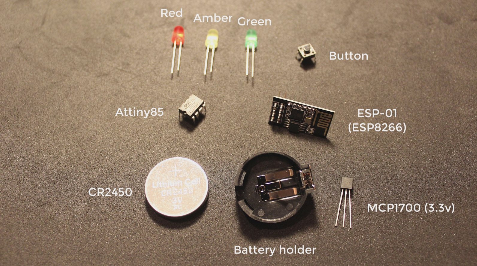
- 3 LEDs, red, yellow/orange/amber, and one green.
- 3 220 Ohms resistors
- A button (any kind)
- Attiny85 (or any micro-controller)
- ESP8266 (ESP-01) for wireless connectivity (optional)
- Any coin battery and its holder
- I use the CR2450
- Any 3.3v voltage regulator
- I use the MCP1700.
- To upload code to the Attiny and the ESP-01 you will need a USB ASP and a USB UART.
- If you are 3D printing the case for it, you will also need:
- 5 M2 bolts
- A sliding switch to turn off and on.
- That's all!
Gather Around All the Components
Wiring

Connect everything up on a breadboard. Please note that I don't use a resistor for the amber and green LEDs as it made them way too dim, however, your LEDs may be fine. So first use the resistors, and if the LEDs are really dim, then take away the LEDs.
For now, leave the ESP01 unconnected, we will connect it later, for now, we will just control the traffic light using the button.
Uploading the Attiny85 Code

The code can be found here.
You will need a USB ASP to upload to the Attiny85.
Make the connections on the image, and upload the code by choosing the USBASP as the programmer, burn bootloader, and upload using programmer in the Arduino IDE.
Demo of Breadboard Version

Connect the battery and press the button, you will see the traffic light change with each button press.
Wireless Connectivity


To control the traffic light from your phone. Make the new breadboard connections like on the image.
Then install the Blynk app on your phone
- Create a new project and select ESP8266 as the micro-controller and WiFi as the connection type.
- Add 4 styled buttons and assign the virtual pins 0, 1, 2, and 3 respectively.
- By then, you would have received an email from Blynk when you created the project on the Blynk app, so take note of that authentication code.
Refer to the image on how the Blynk project should look like.
Uploading the ESP-01 Code


In the Arduino IDE, install the Blynk library using the Arduino Library manager. In the ESP-01 code, insert your authentication code received by email from the Blynk app, and put your WiFi and password so the ESP-01 can connect to the WiFi. Make the connection between the ESP-01 and the USB UART like in the image and upload the code to the ESP-01.
Now you will be able to control the traffic light using button and on your phone!
3D Printing!


You could stop here. But if you want to create a real looking traffic light and you have a 3D printer, then print all the parts!
Soldering and Assembly

Solder everything together following the breadboard wiring. I highly recommend you watch the video here on the section where I assemble the traffic light as it will make everything much easier for you.
After soldering everything together, you can simply route all the wires and put the whole traffic light together!
Done!

You should now have a traffic light that looks like a real traffic light, operates like a real traffic light, and can be controlled using a button or wirelessly using your phone!