Wired Laser Pointer (Cat Toy)

.png)
.png)
I made a manual remote control laser pointer. Mainly out of spite for and me not wanting to buy new batteries for an old laser pointer I had.
The code I created for this project is:
/*
 ╔════════════════════════
 ╠ PROGRAMMER: Curtis Houston
 ╠ DATE: 20/01/2022
 ╠════════════════════════
 ╠ Manual Laser Pointer
 ╠════════════════════════
 ╠ DESCRIPTION:
 ╠  Laser pointer designed to be aimed
 ╠  by a joystick, controlled by the user
 ╠════════════════════════
 ╠ CONNECTIONS
 ╠ Pins 4-9(Digital), A0 and A1 (Analog)
 ╚════════════════════════
*/
#include <Servo.h> // includes the servo library

Servo sev1; // names one servo motor sev1
Servo sev2; // and the other sev2

const int Horiz = 0; // analog pin connected to X output
const int Verti = 1; // analog pin connected to Y output

const int Power = 9; // switch pin that'll be used to control power
const int xSwitch = 8; // switch pin used to flip the x-axis
const int toggle = 7; // switch pin used to toggle the power to the LED/Laser
const int led = 4; // LED/Laser Pin

int x = 0; // creates an interger named x

void setup() // runs code once
{
 sev1.attach(6); // attaches sev1 to pin 6
 sev2.attach(5); // and sev2 to pin 5
 pinMode(led, OUTPUT); // sets the LED connected to pin 4 as an output
}

void loop() // runs code infinitely
{
 if (digitalRead(Power) == 1) // checks the power switches input if powered, run code in brackets
 {
  sev1.attach(6); // initalize sev1
  sev2.attach(5); // and sev2

  if (digitalRead(xSwitch) == 1) // checks the x-axis toggle switch for power
  {
   x = 1023-analogRead(Horiz); // make the x interger equal to effectivly the invert of A0

   sev1.write(x); // set sev1 position to that of the x value
   sev2.write(analogRead(Verti)); // set sev2's position to the value given by the A1 potentiometer
   delay(2); // pause the code for 2 microseconds, for a buffer

   if (digitalRead(toggle) == 1) // checks the toggle pin to see if its powered
   {
    digitalWrite(led, HIGH); // if powered turn the LED on
   }
   if (digitalRead(toggle) == 0) // checks the toggle pin to see if its unpowered
   {
    digitalWrite(led, LOW); // if so turn off the LED
   }
  }
  if (digitalRead(xSwitch) == 0) // if the x-axis switch is unpowered
  {
   x = analogRead(Horiz); // make the interger x equal to the value givin by A0

   sev1.write(x); // set sev1 position to that of the x value
   sev2.write(analogRead(Verti)); // set sev2's position to the value given by the A1 potentiometer
   delay(2); // pause the code for 2 microseconds, for a buffer

   if (digitalRead(toggle) == 1) // checks the toggle pin to see if its powered
   {
    digitalWrite(led, HIGH); // if powered turn the LED on
   }
   if (digitalRead(toggle) == 0) // checks the toggle pin to see if its unpowered
   {
    digitalWrite(led, LOW); // if so turn off the LED
   }
  }
 }
 if (digitalRead(Power) == 0) // if the toggle switch controlling power is unpowered
 {
  sev1.detach(); // disconnect sev1
  sev2.detach(); // and sev2
  digitalWrite(led, LOW); // turn off the LED
 }
}
Supplies
1 Breadboard
1 Arduino Uno
4 AA Batteries, in a casing
2 Potentiometers or alternatively 1 Joystick
2 Servo Motors
3 Sideswitches
3 10k Ohm Resistors
3 1k Ohm Resistors
1 220 Ohm Resistor
1 Laser Diode (or an LED)
All in One Place

Gather your supplies, Make sure everything works.
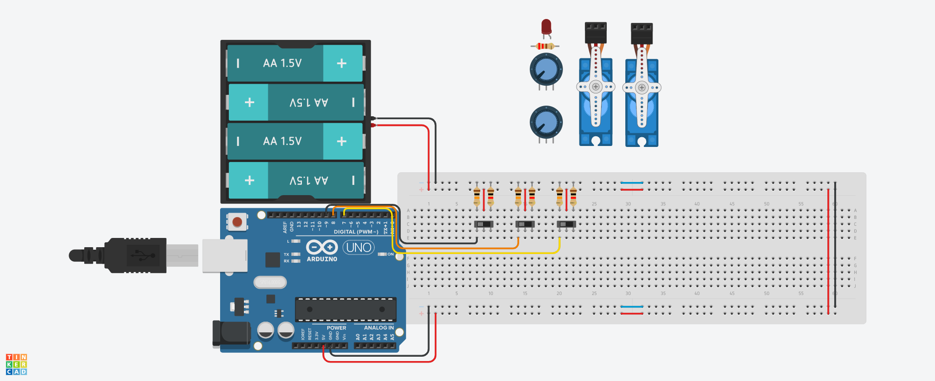
Your Power and Ground
.png)
Connect your Arduino and battery as well as your top and bottom rails. Your Arduino's 5v and the battery's positive pins will be connected to the + rails on the breadboard. The GND pin and the negative pin on the battery will be connected to the - rails on the breadboard. Next, connect the two sides where ever you'd like, keep in mind the positive rails need to be connected and the negative rails need to be connected; you can't cross them.
Switches
.png)
Connect your switches to Arduino pins 7, 8, and 9. You'll see me use different coloured wired often, this is to make it easier to tell what my components do, in this case, the switch connected by a black wire will control power, the orange one will flip the value given on the X-Axis, and the yellow will turn on and off the laser alone.
Potentiometer
.png)
The potentiometers are a stand-in for TinkerCAD's lack of a joystick, they are used to control the position of the servo motors, connect them to analog pins A0 and A1. Note: the code below should still work with a joystick.
Servo Motors
.png)
For our second last step, wire up the servo motors, these will be connected to pins ~6 and ~5, keep in mind that the potentiometer connected to A0 will control the servo motor connected to pin 6, the same is true for A1 and 5.
The Laser (or LED)

Once more, due to the limitations of TinkerCAD, an LED will be used instead of the laser diode we originally planned for, once the LED is connected to pin 4 You're done! congrats!