Window Repairs Using Fusion 360 Saved Me Over $300
by DanPro in Workshop > Repair
1903 Views, 14 Favorites, 0 Comments
Window Repairs Using Fusion 360 Saved Me Over $300
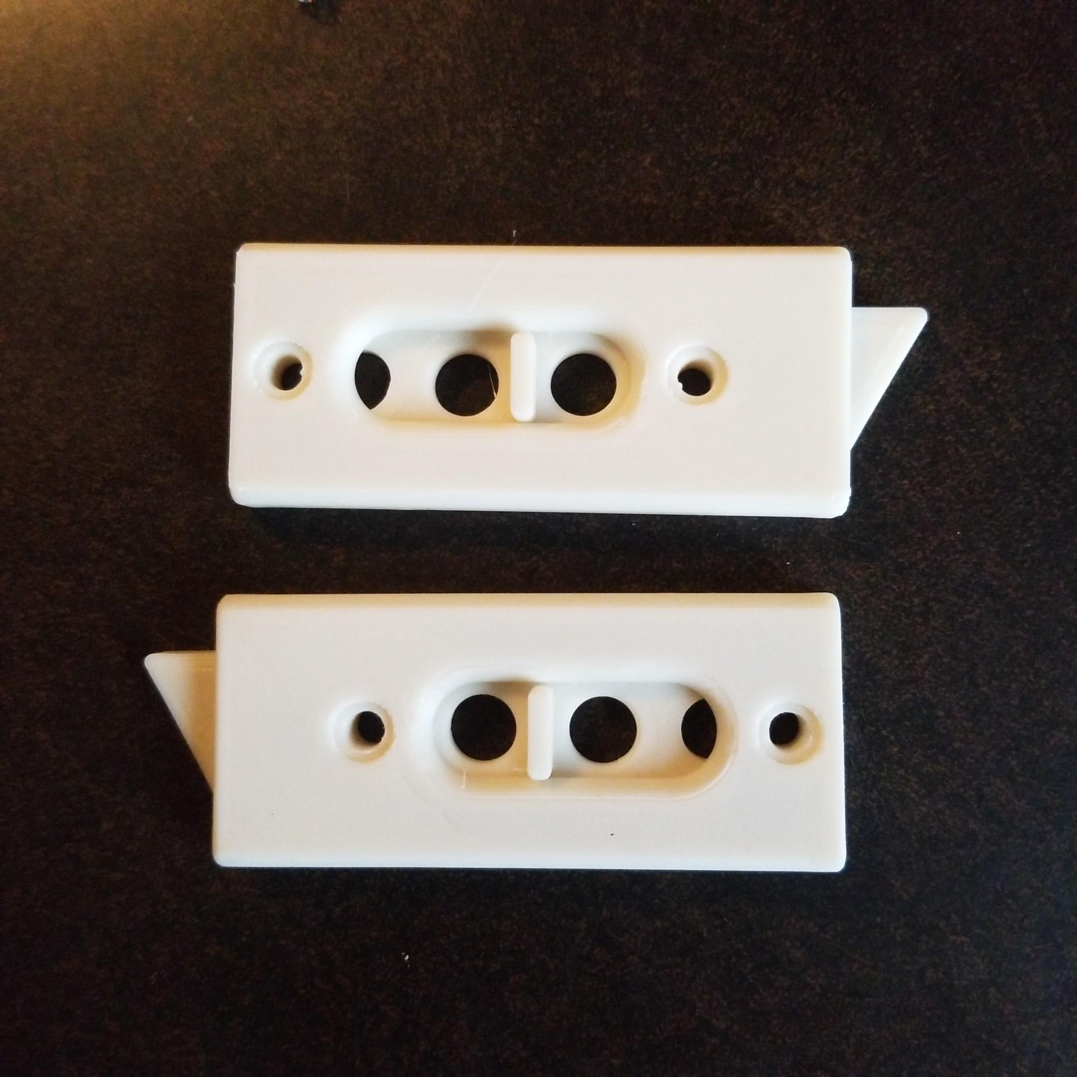
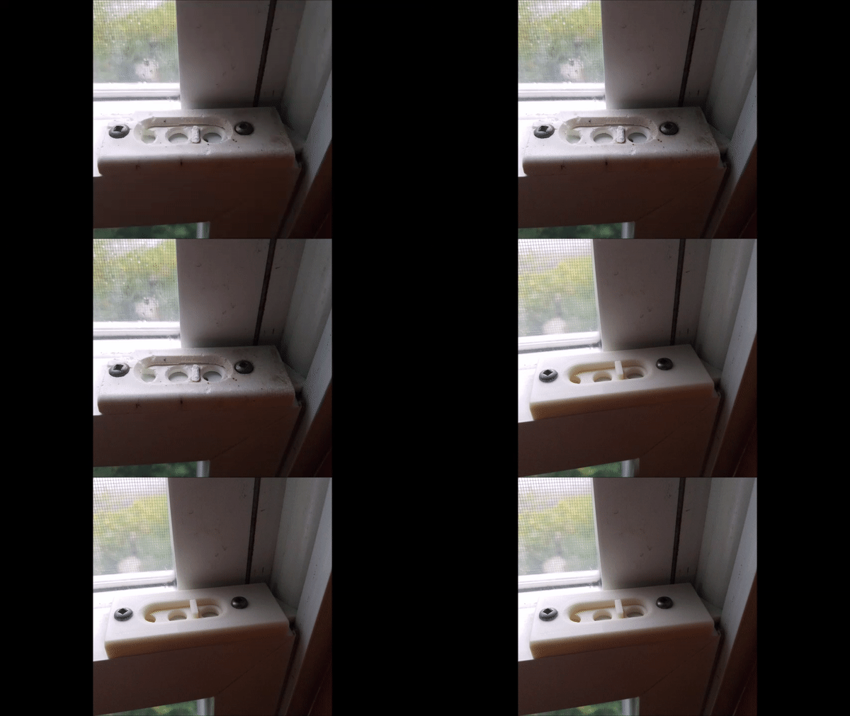
My double hung windows have latches that allow you to swing the window in for cleaning.
After baking in the sun for more than 30 years, these latches are turning to dust.
In fact if someone pushed on the outside of the window, they could easily break the latch.
Luckily heavy winds haven't blown them in on someone.
Searching for replacement parts was frustrating.
Some looked pretty similar but had bad reviews.
Some wouldn't ship to Canada, etc. etc.
Even if they fit, $20 plus shipping per pair and 16 windows to repair added up quickly.
Instead, I've used Fusion 360, my laser jet printer's scanner and my Creality ender 6 3d printer to create replacements.
Remove Old Latch
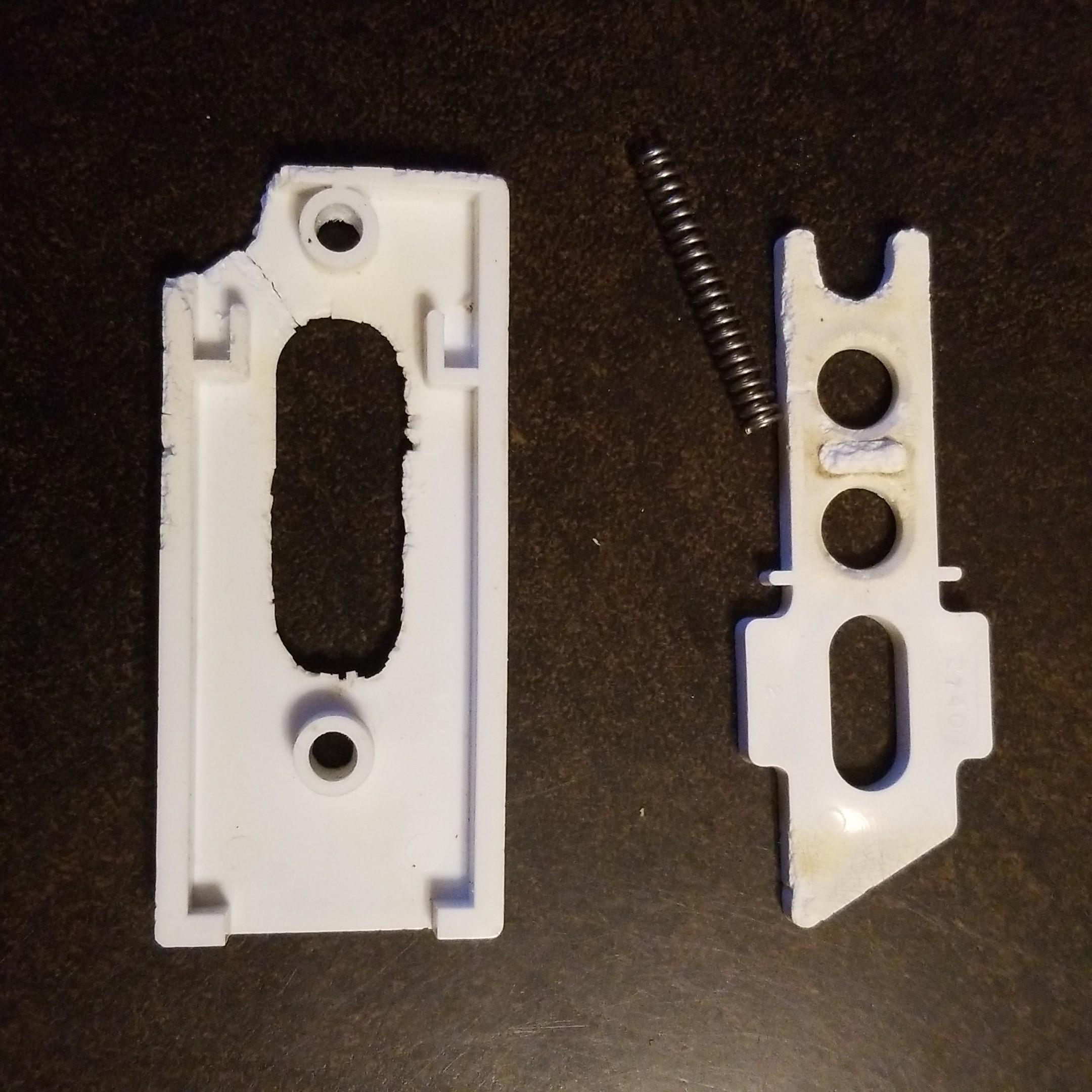
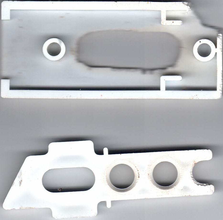
I carefully removed a latch to use as a template and scanned it.
I'm going to reuse the springs and mounting screws.
Crop Immage
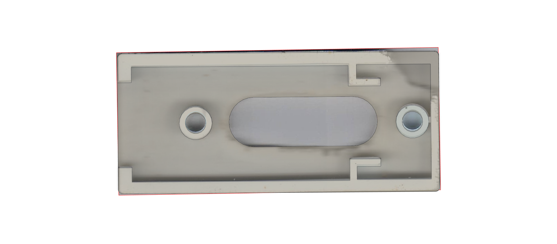
I used the windows 11 snipping tool to crop the image.
Insert the Picture Into Fusion 360
.png)
.png)
.png)
.png)
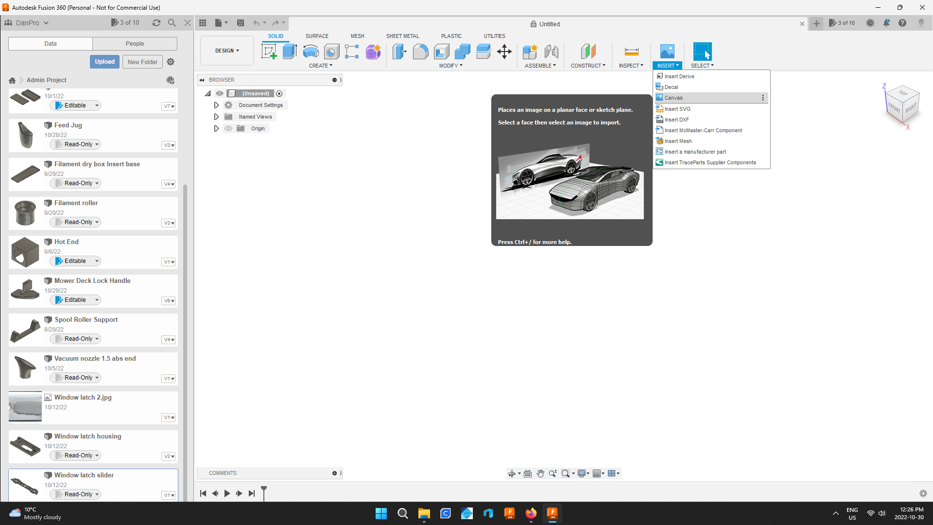
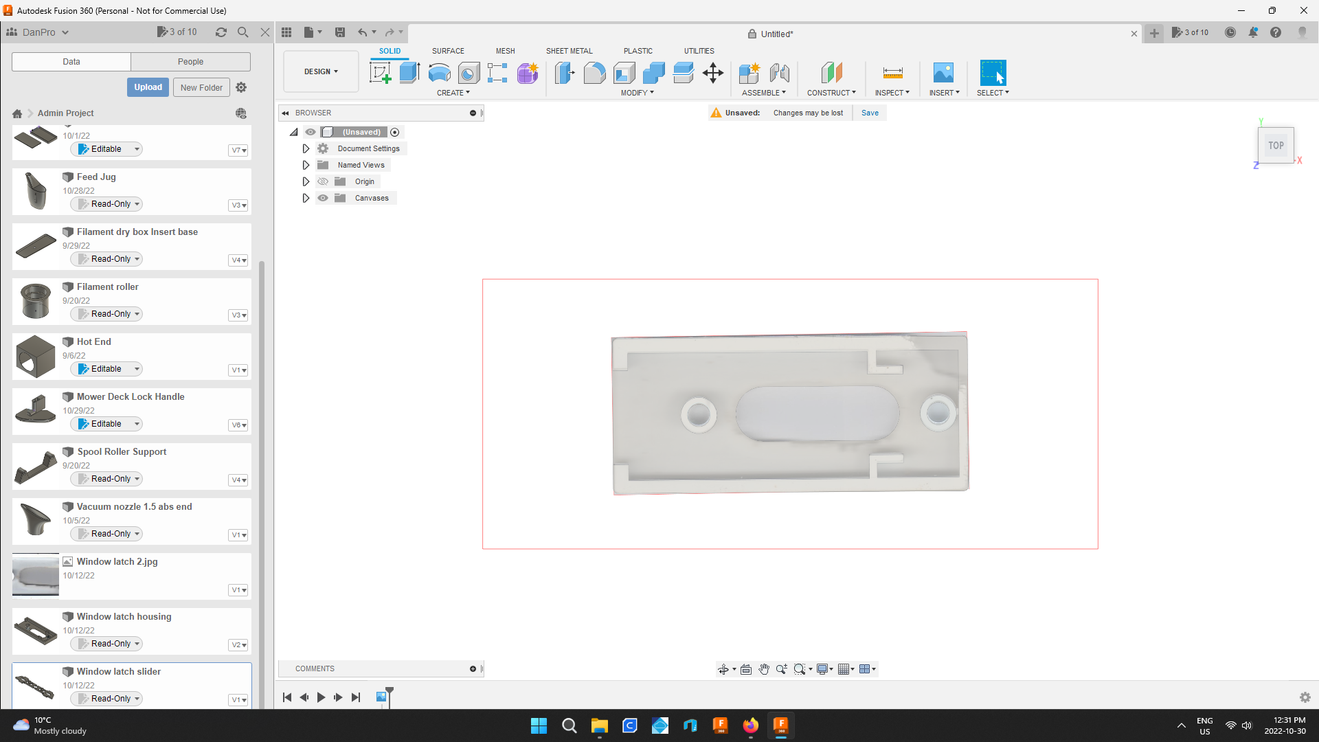
Under the insert tab choose canvas.
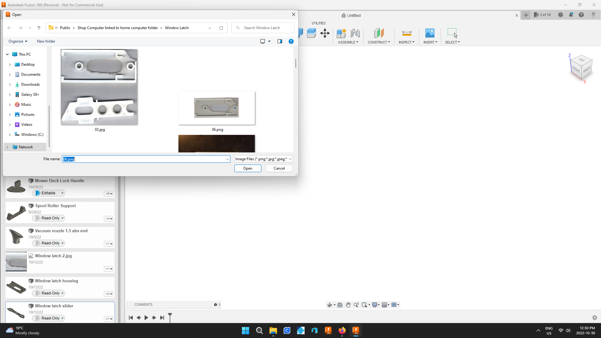
Choose the picture from it's folder.
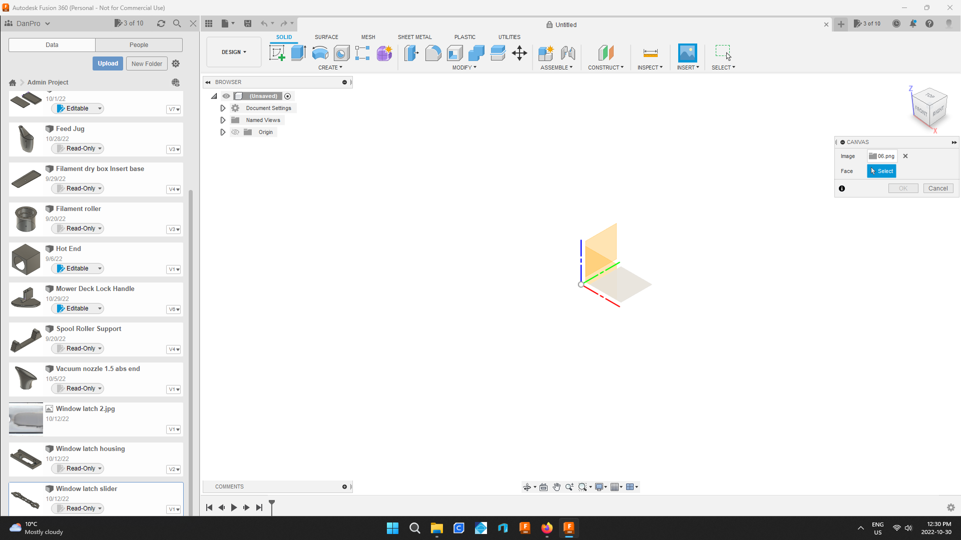
Then click on a plane to work on.
Hit enter then scroll in so you can see the part better.
Set Up the Size Using Calibrate
.png)
.png)
.png)
.png)
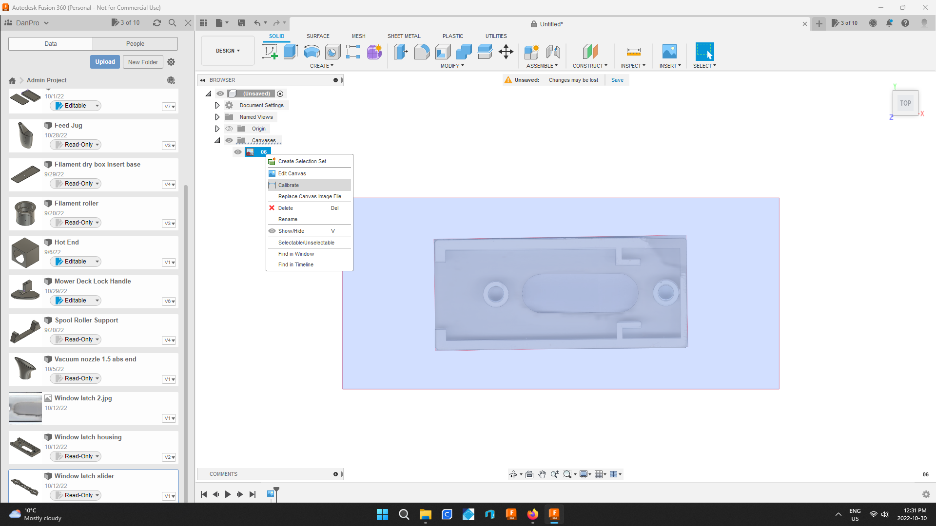
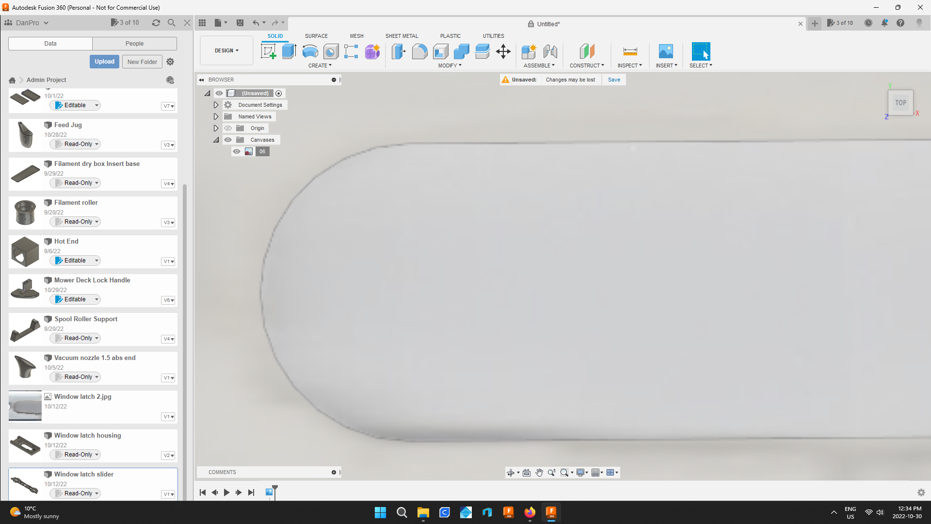
Open the drop down menu titled canvases.
Right click on the file name and choose calibrate.
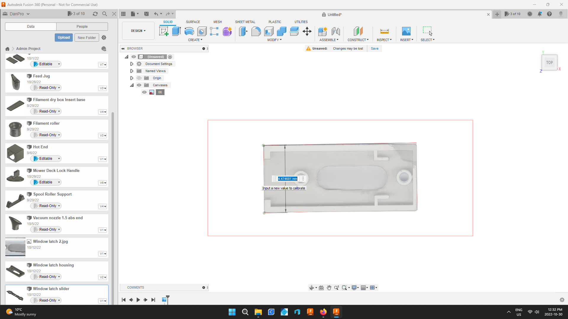
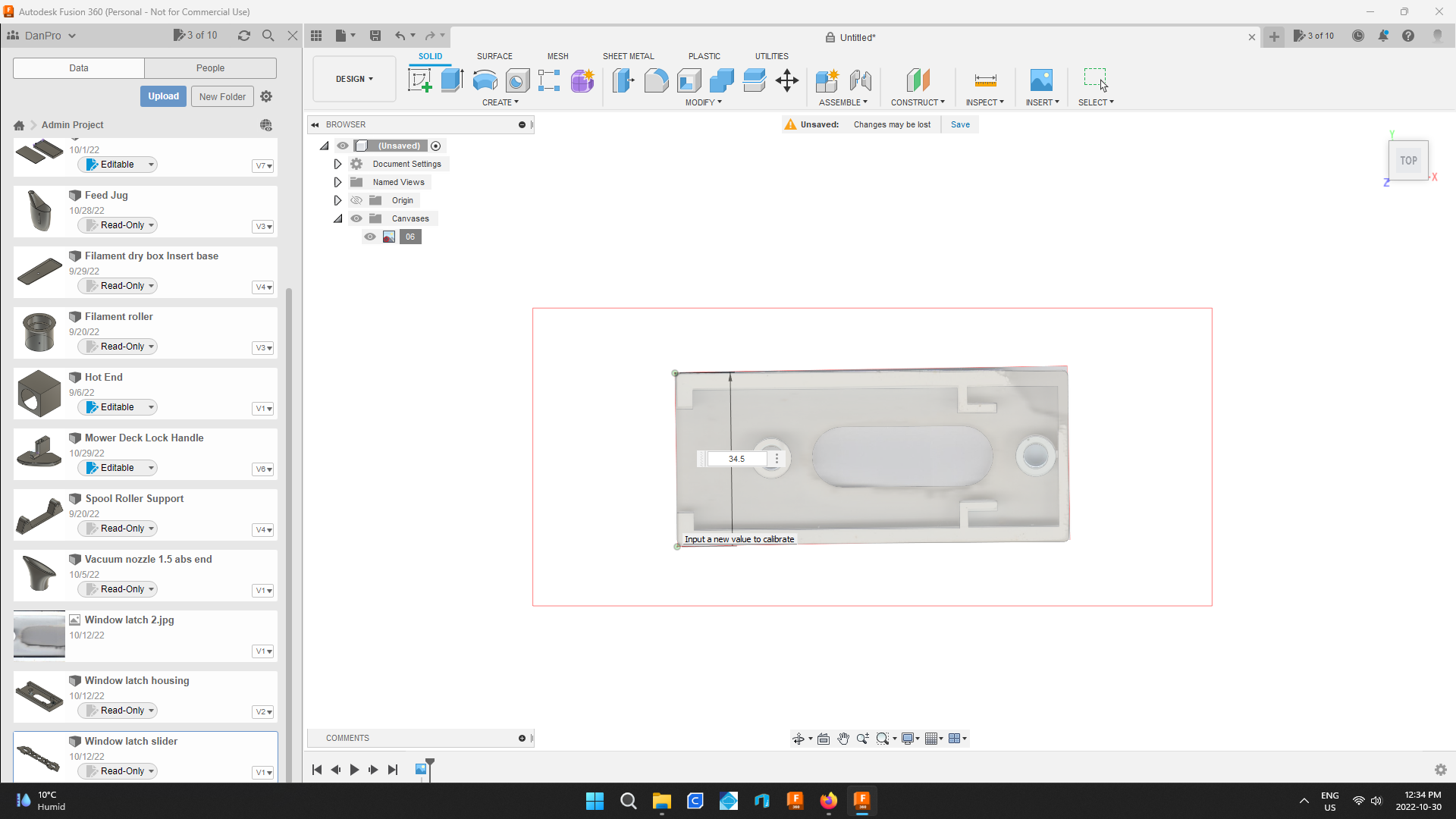
Choose two points and enter the proper dimension between them.
When enter is pressed the canvas will expand to its proper size.
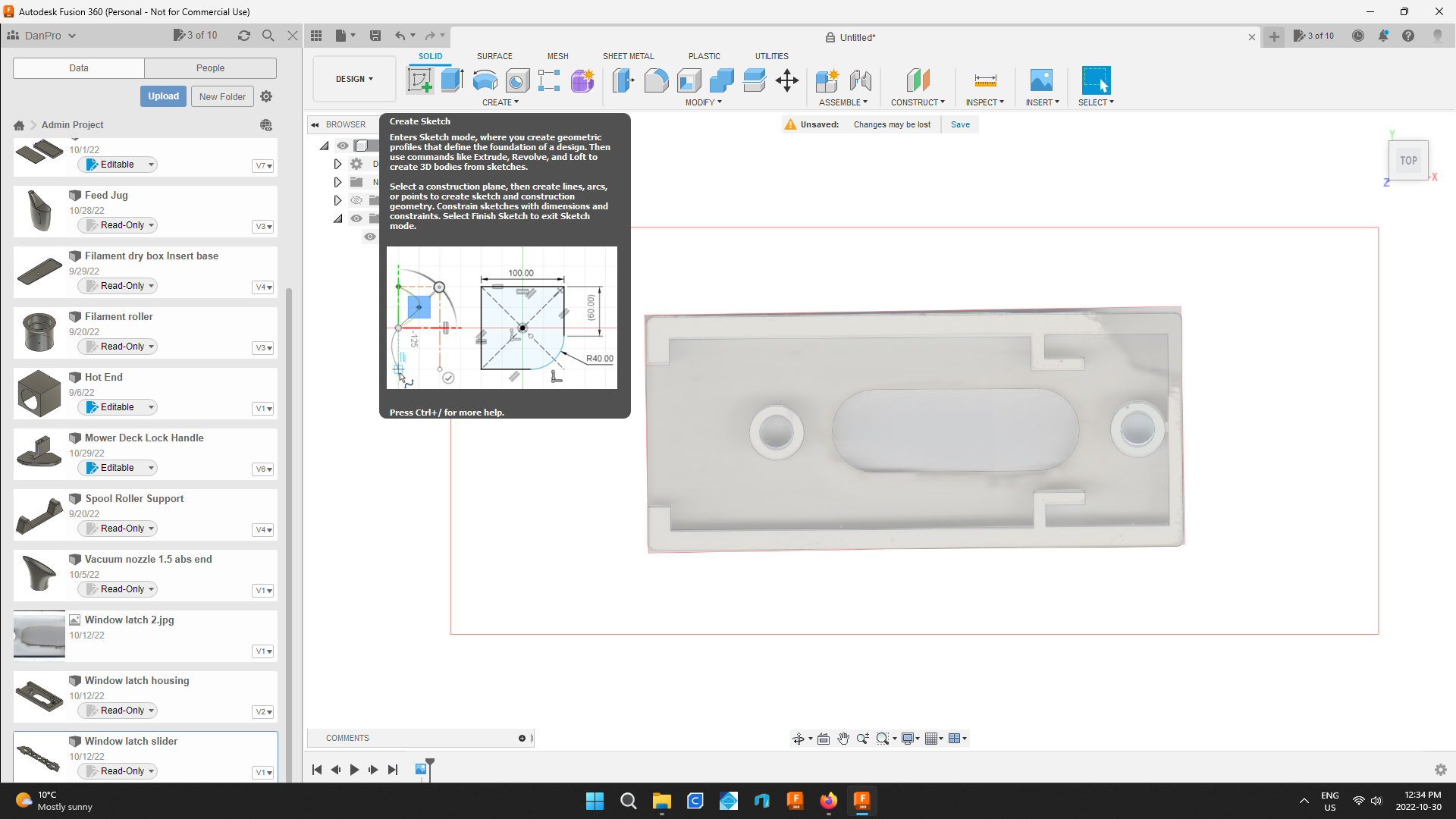
This image is a great help. Drawing over it saves having to measure every dimension of the part.
Sketch a Horizontal Line
.png)
.png)
.png)
.png)
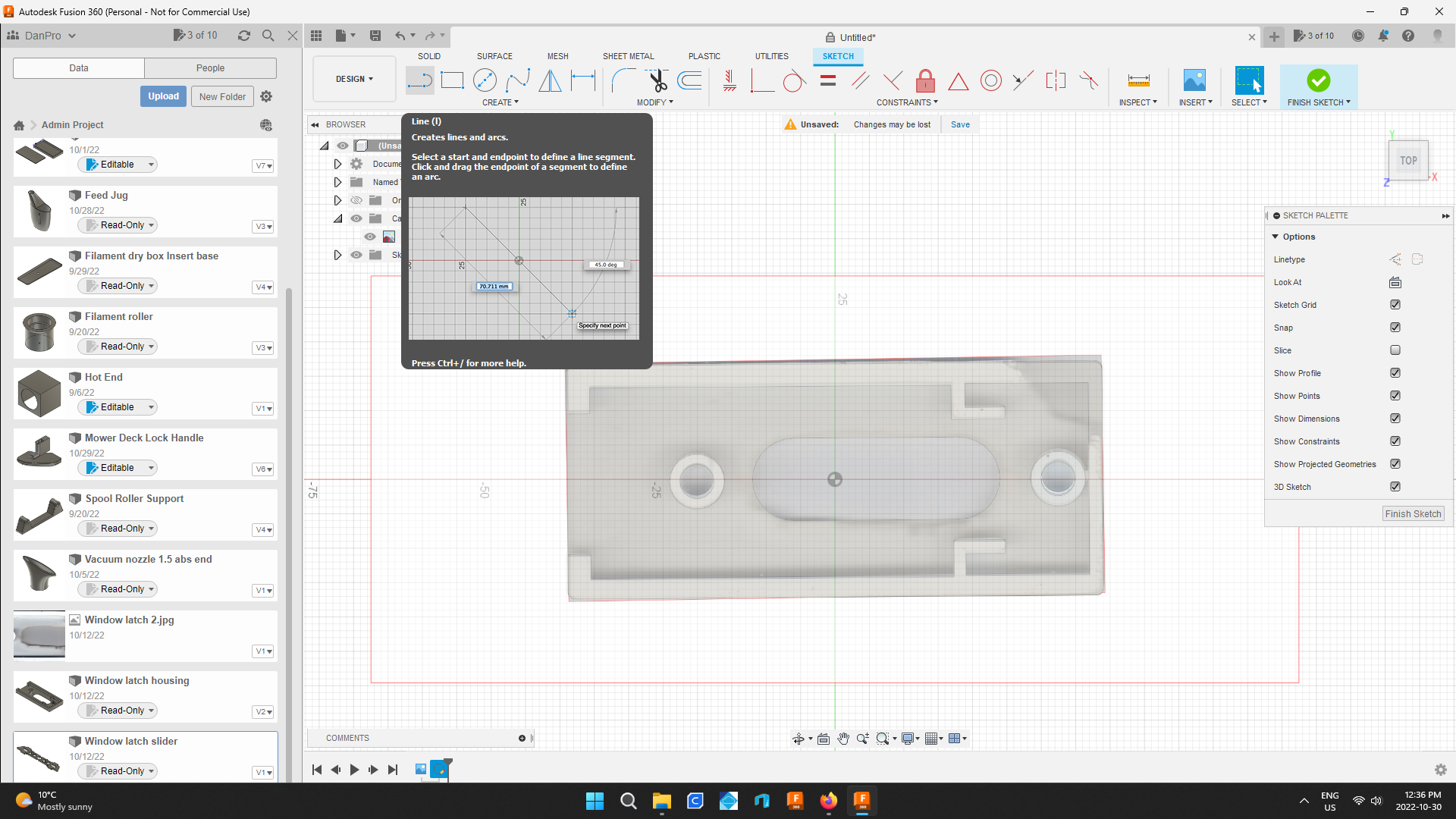
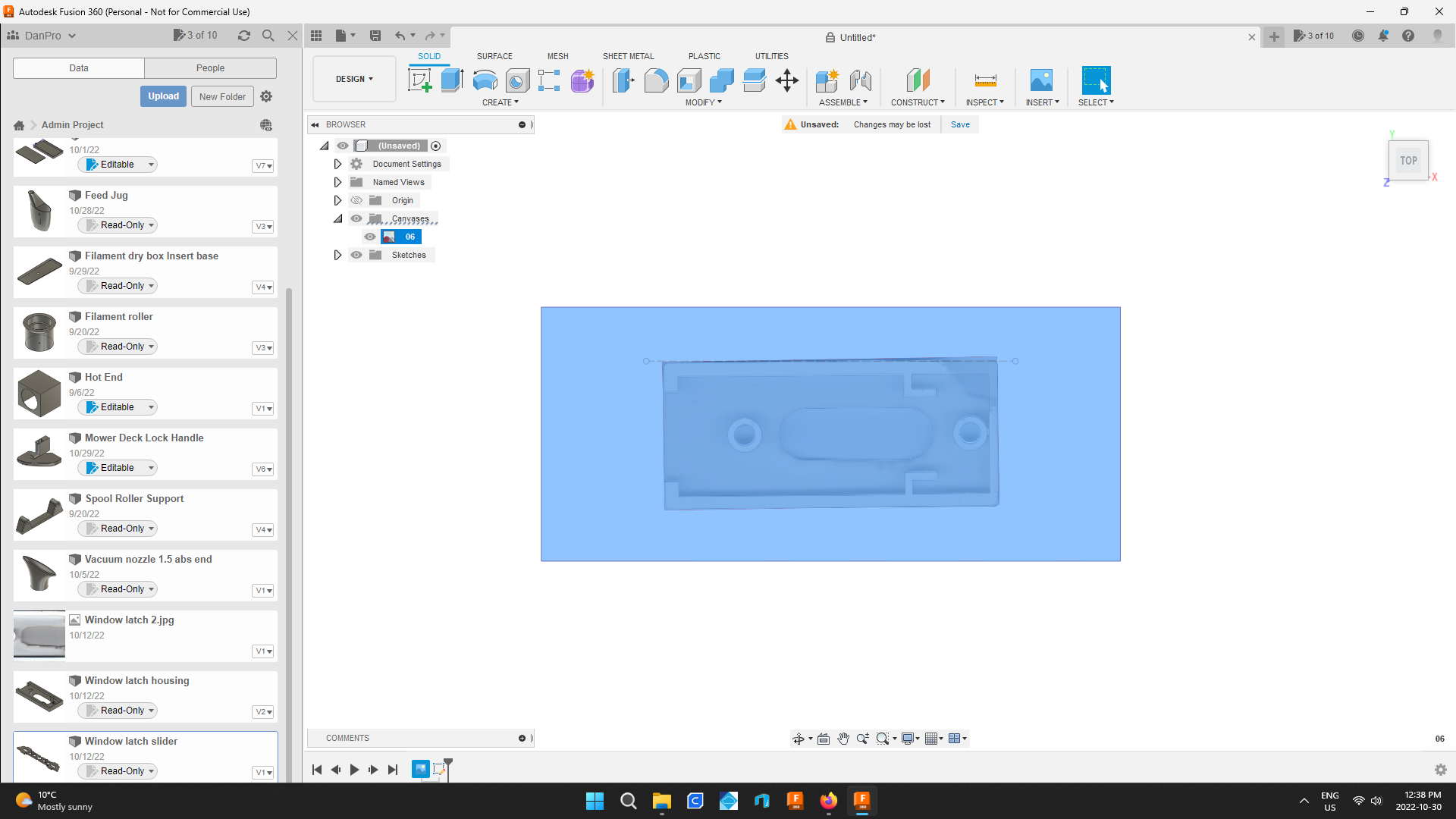
Choose create sketch then click the canvas.
Choose create lines and arcs
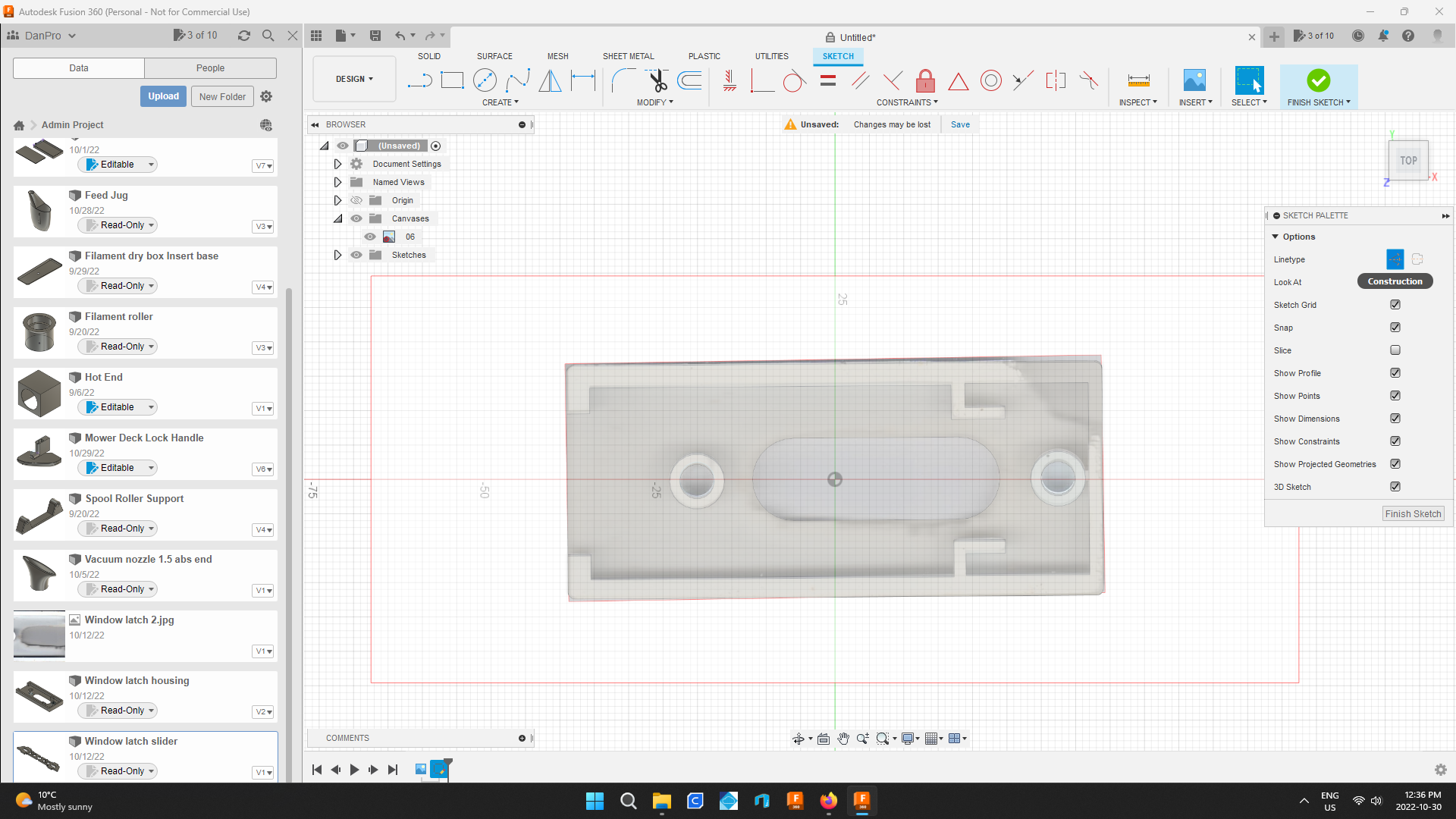
In the sketch pallet choose construction line.
Create a horizontal line along the top of the part.
This will help aligning the canvas so that the part is horizontal.
Move the Canvas to Horizontal
.png)
.png)
.png)
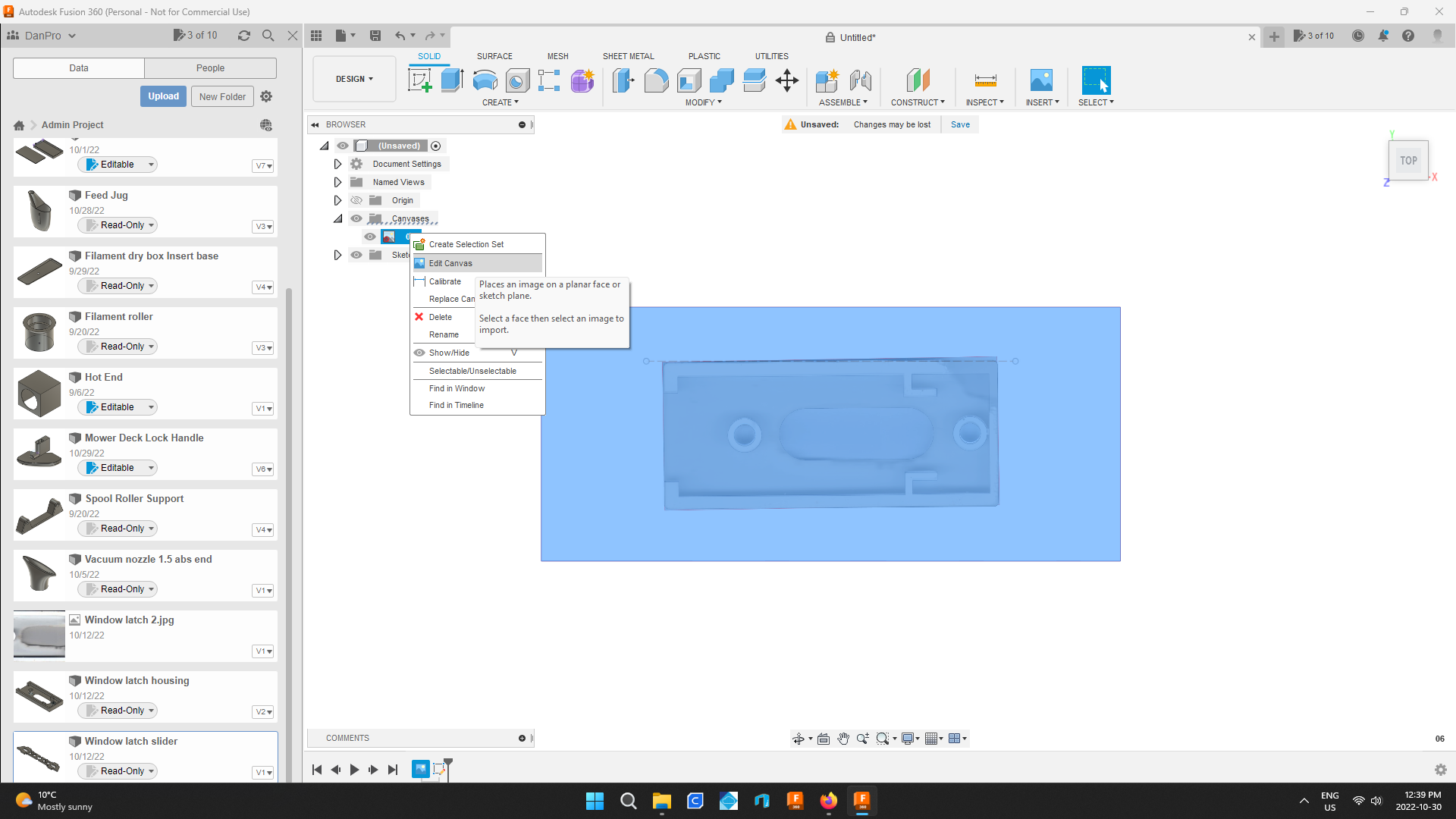
Right click on the canvas menu again and choose edit canvas.
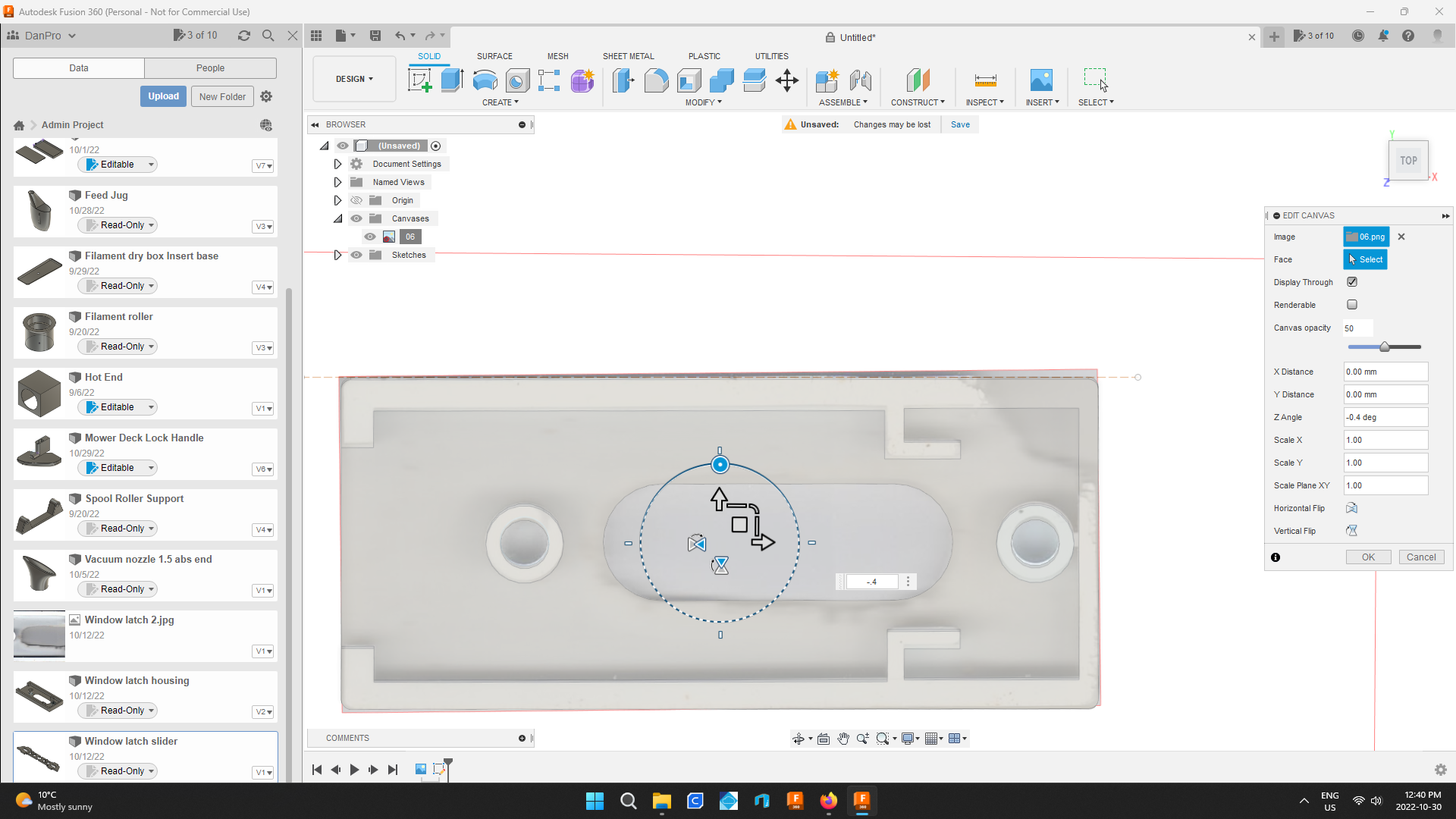
Click on the circle at the top of the edit tool.
In the popup window enter a dimension to rotate the canvas.
It will take a few tries until the top of the part matches the horizontal construction line.
Once aligned hit enter.
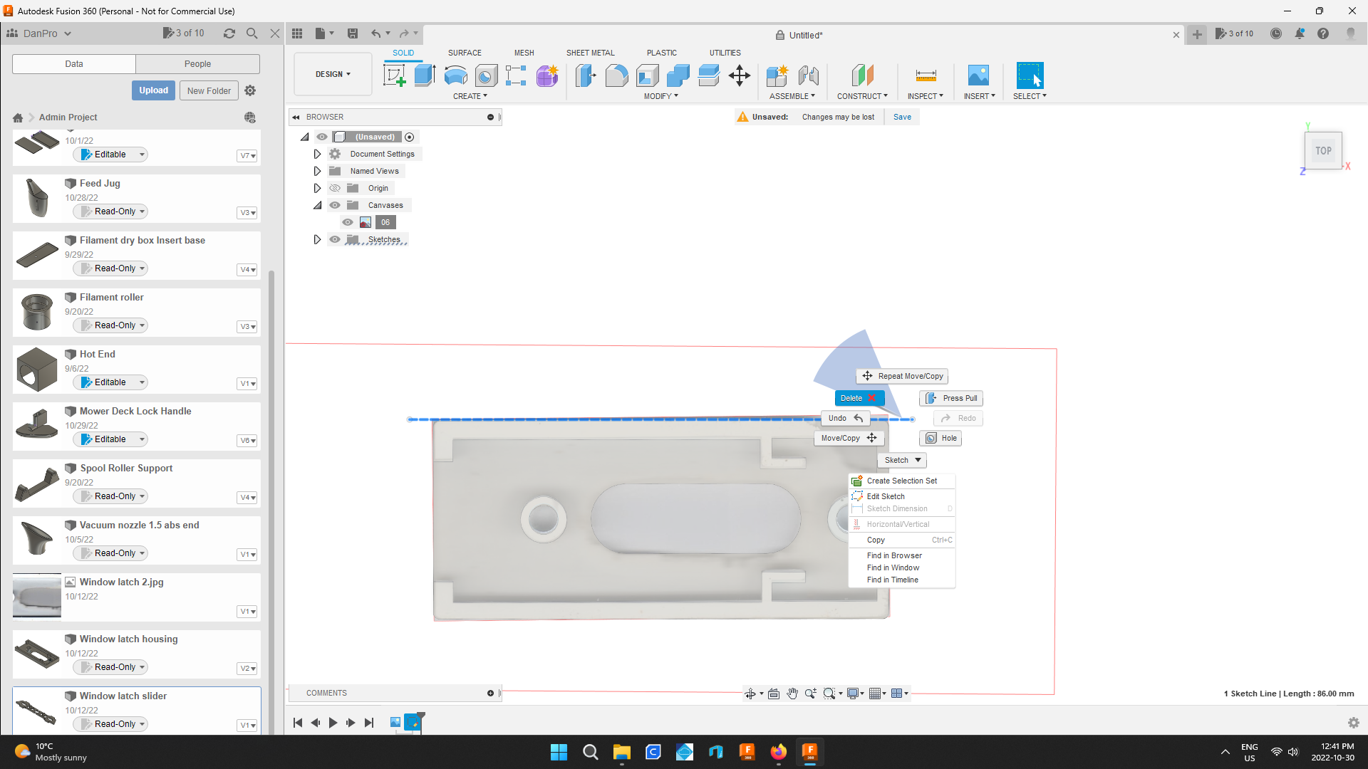
Right click the construction line and select delete.
Sketch Out the Part
.png)
.png)
.png)
.png)
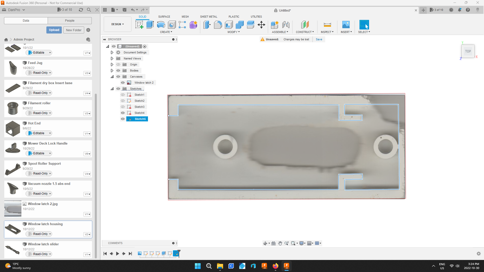
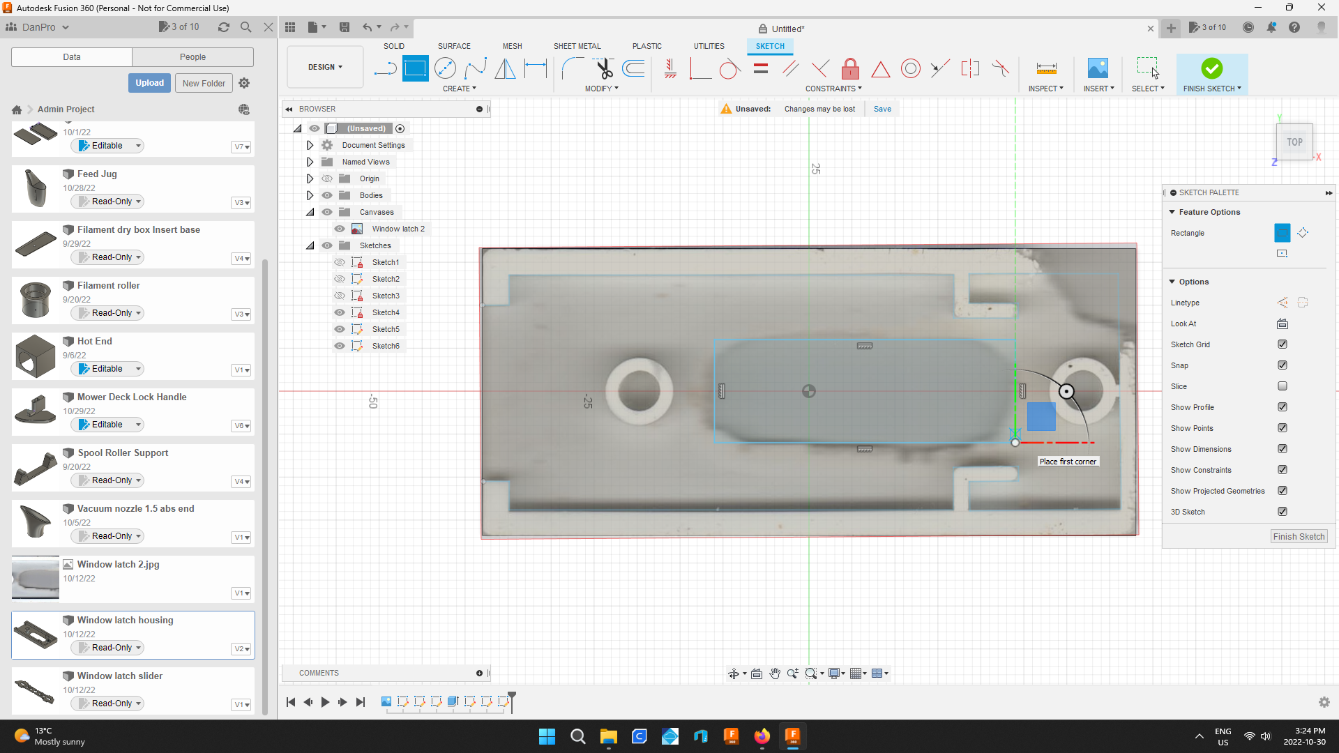
Choose create sketch and click the canvas.
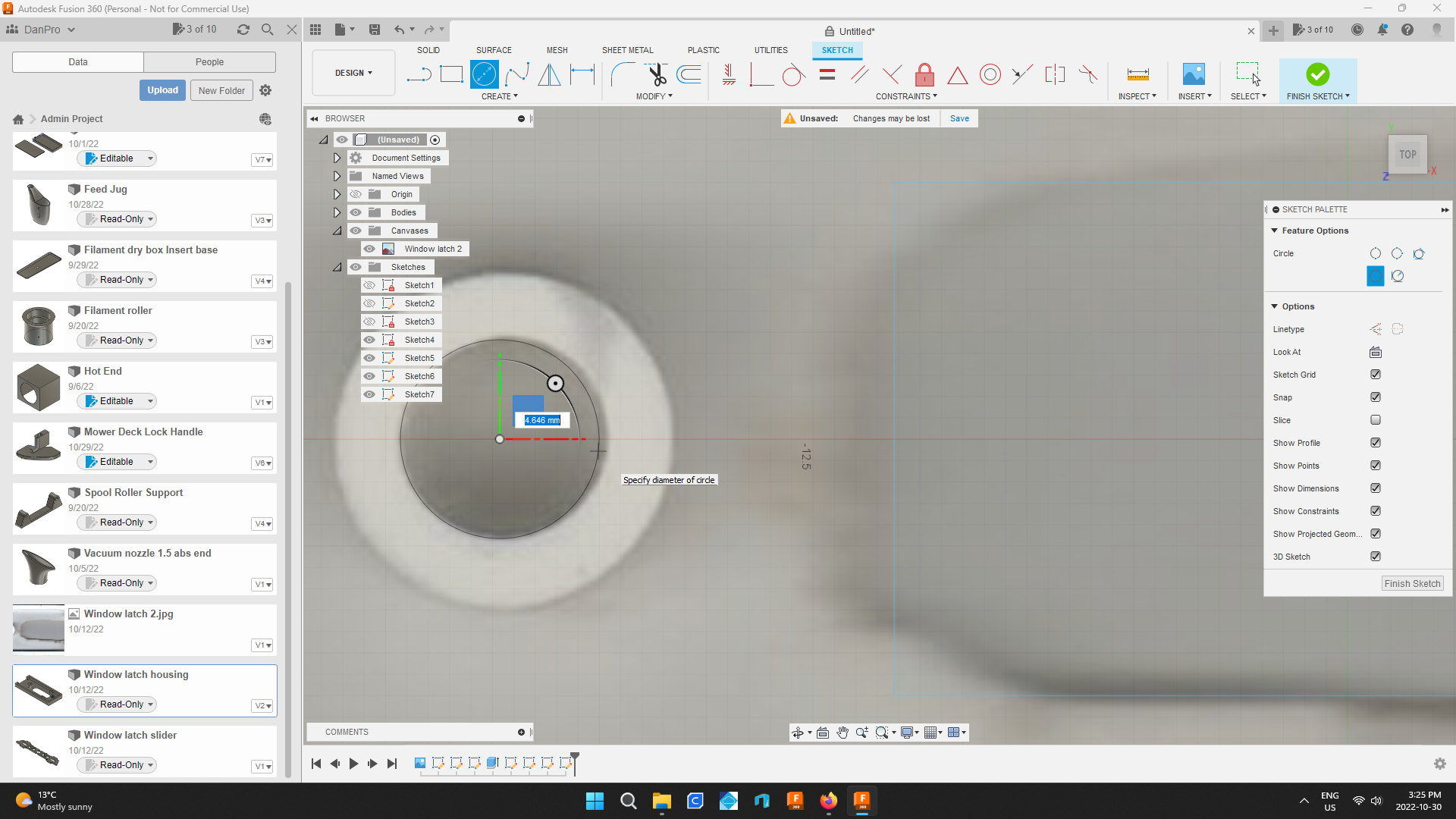
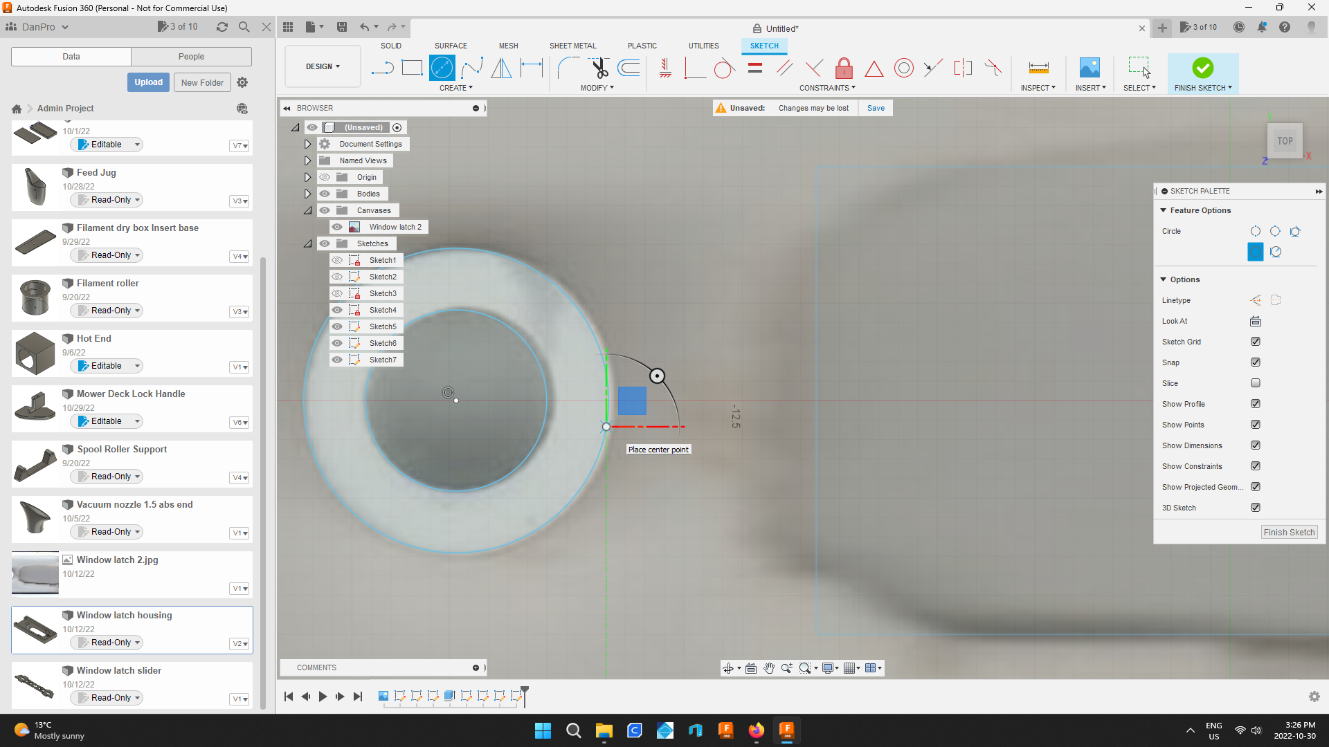
Using the line and circle tools draw out all the part's raised wall lines.
Extrude the Drawing
.png)
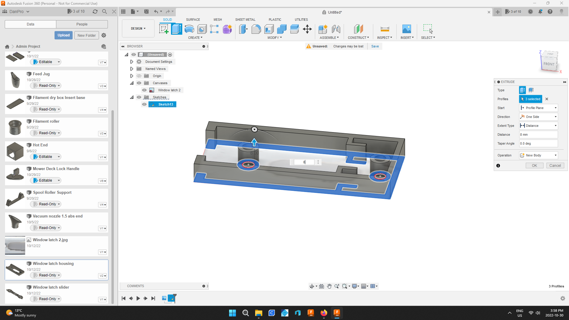
While holding the ctrl key select between the circle lines of both circles and at any point between the other lines drawn.
Once the selection is made select the extrude tool and type in the proper dimension and hit enter.
Create Another Drawing to Create the Square Part
.png)
.png)
.png)
.png)
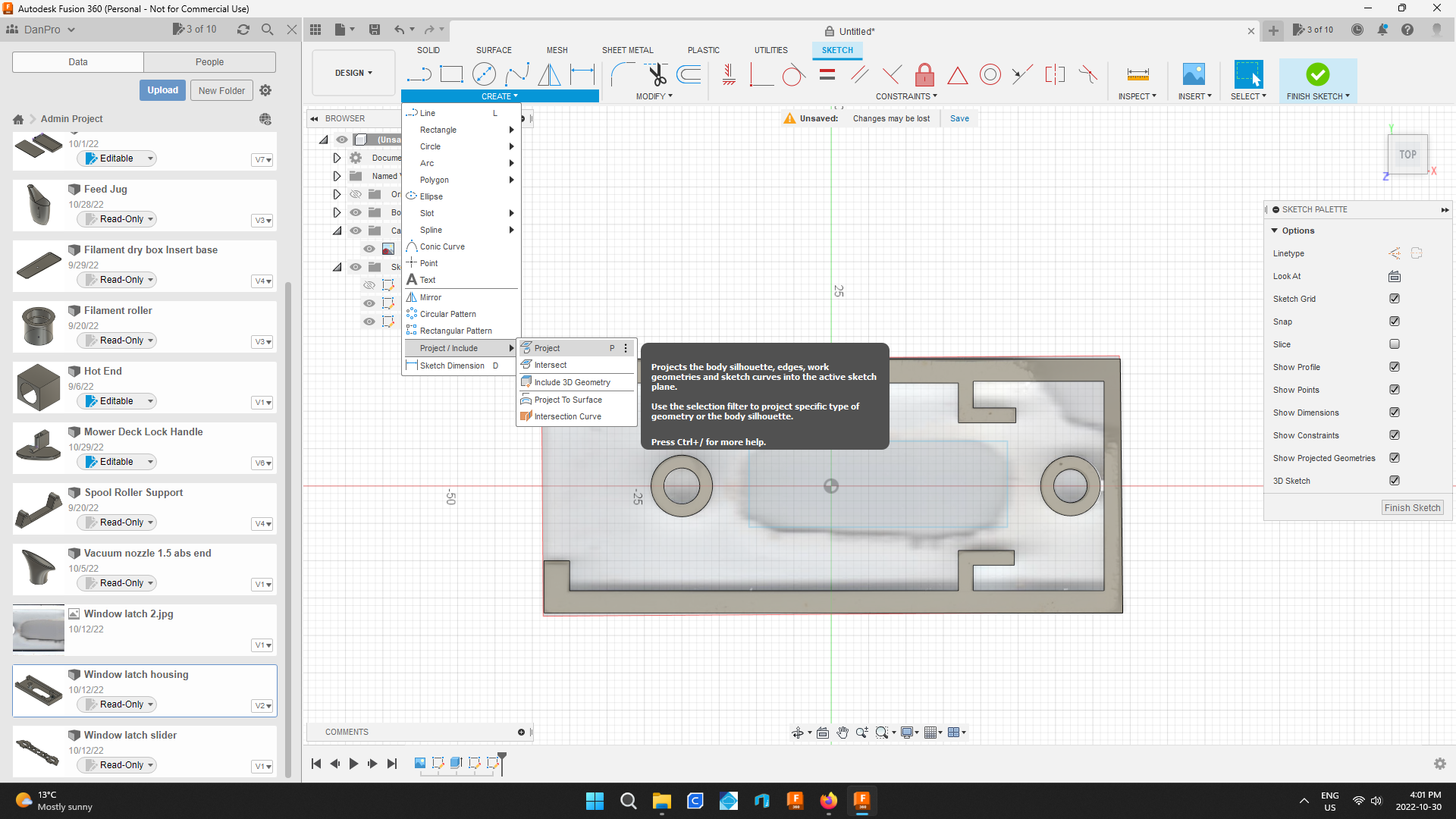
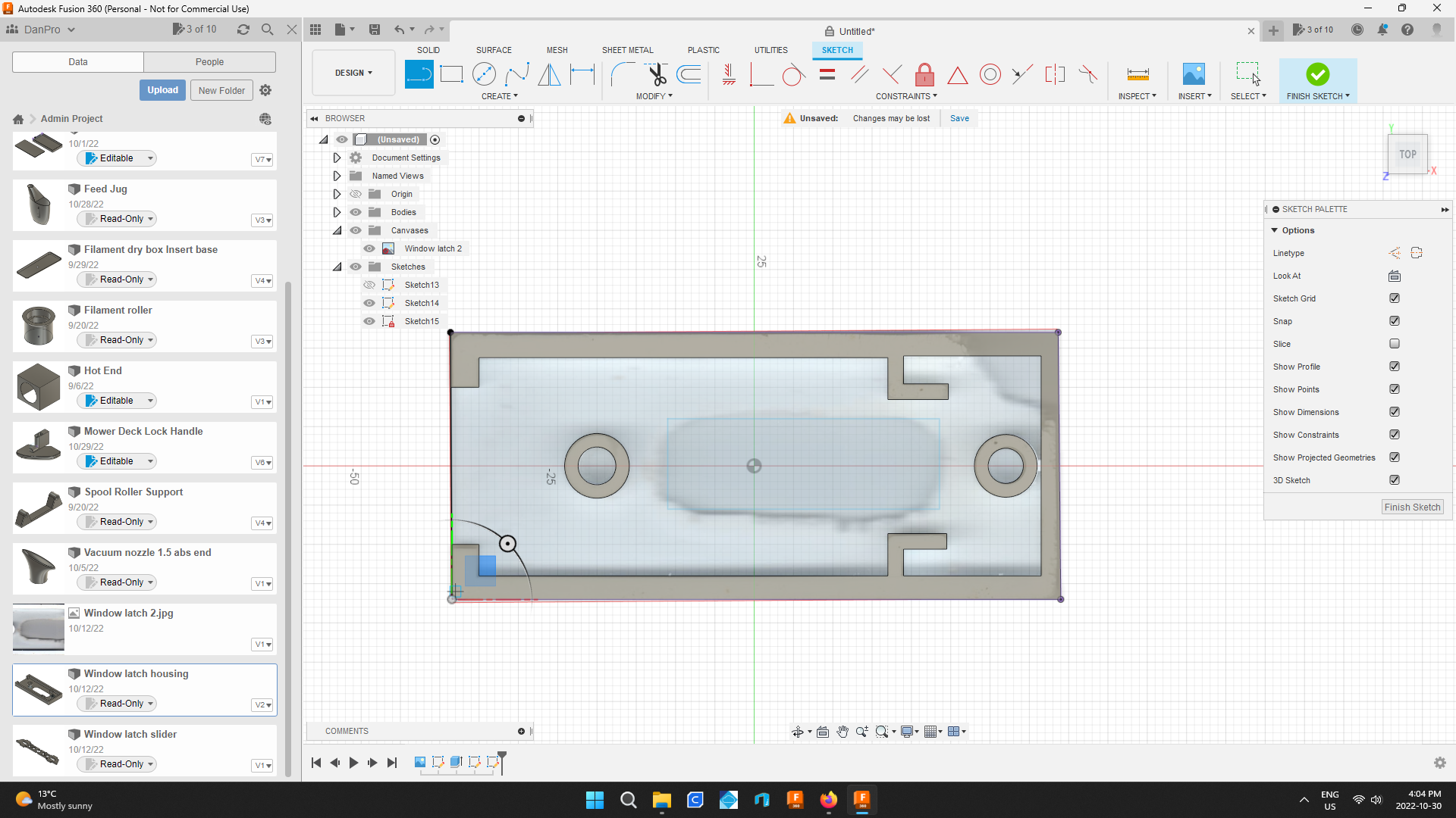
Start a drawing and under create chose project / include then select project.
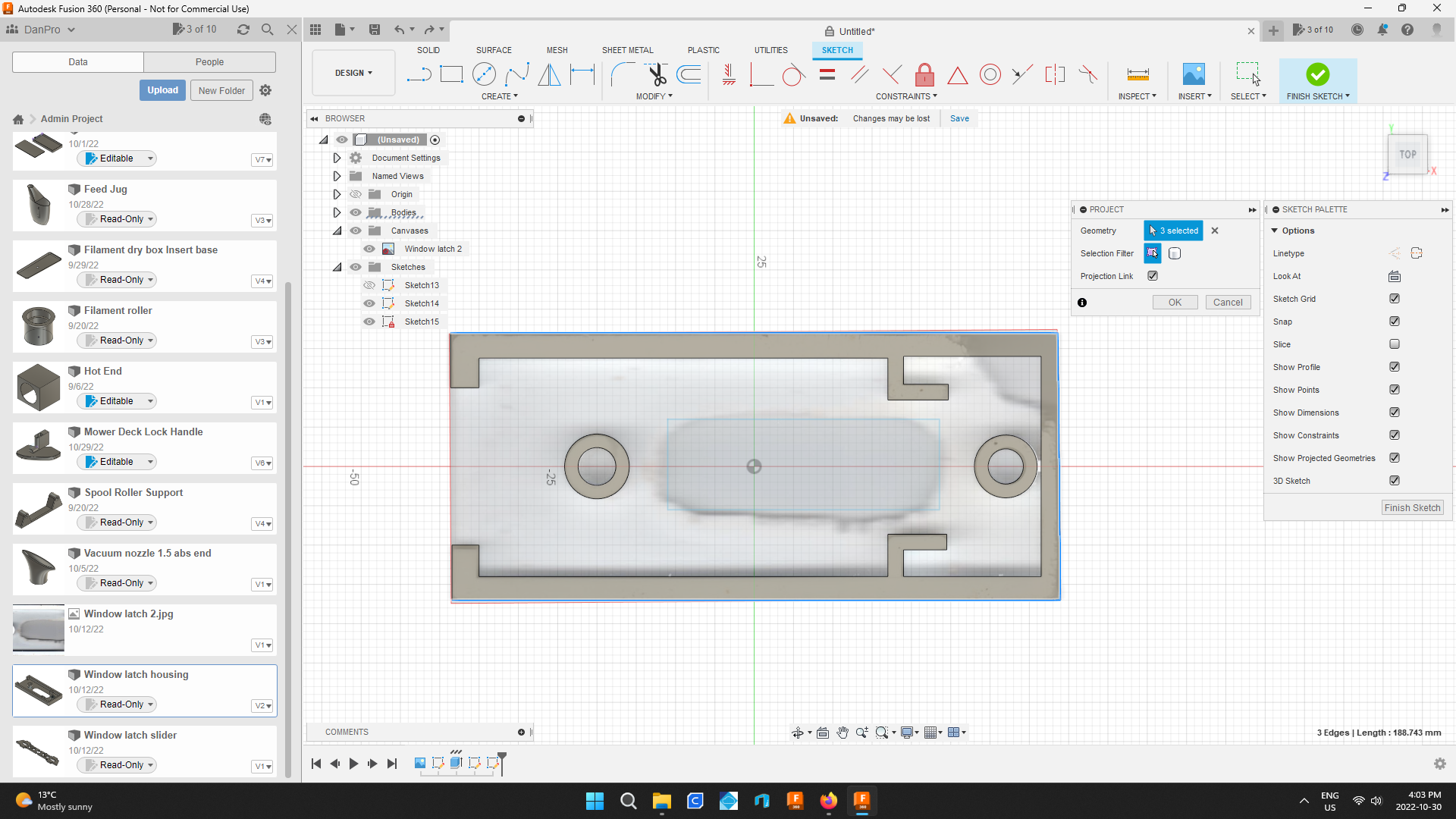
Select the top, bottom and right outside lines while holding the ctrl key then hit the 0k button of the project tool box.
Now these lines are part of this new drawing.
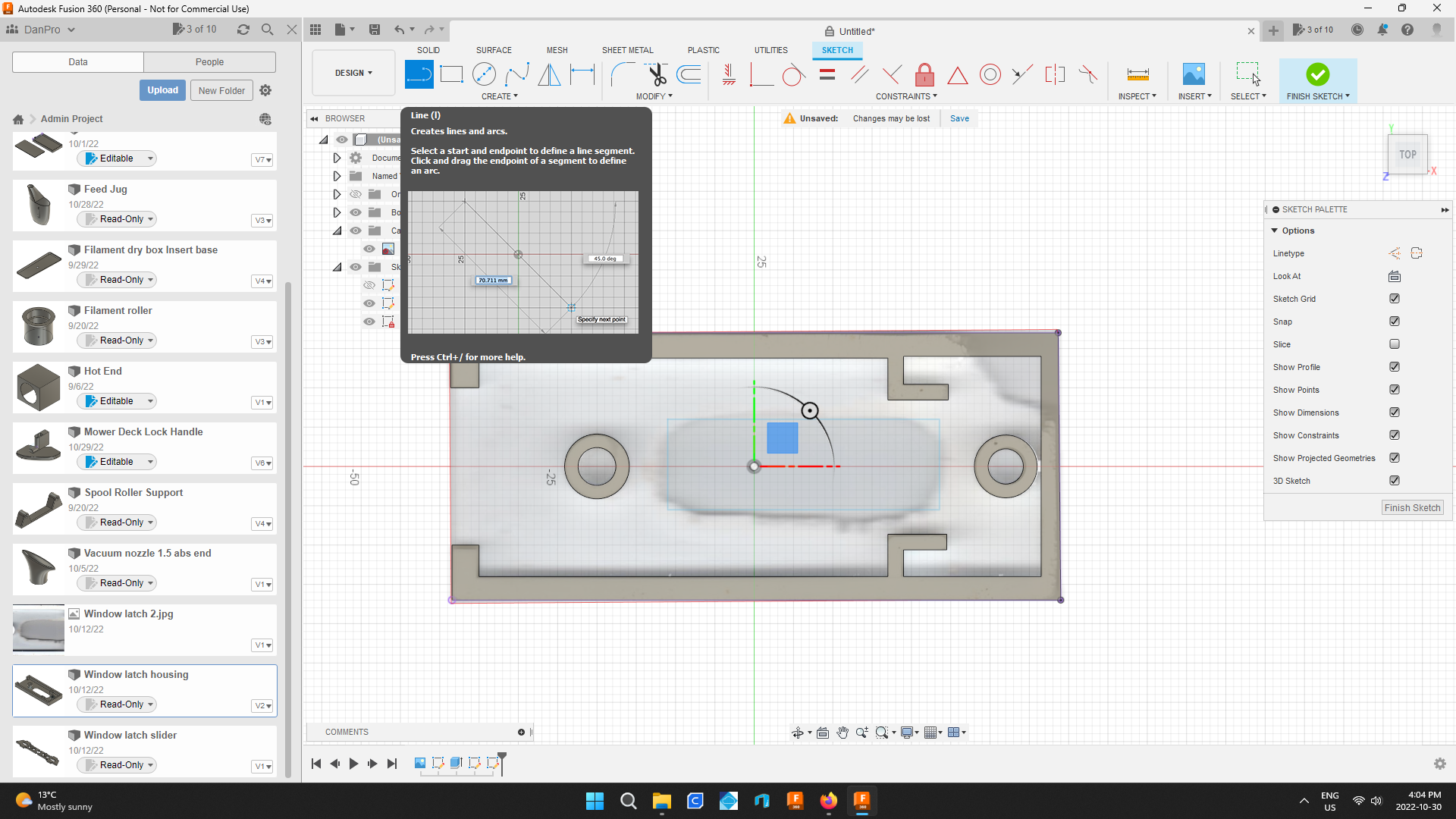
Next use the line tool to complete the left hand side of the square and then select finish sketch.
Extrude the Body of the Part
.png)
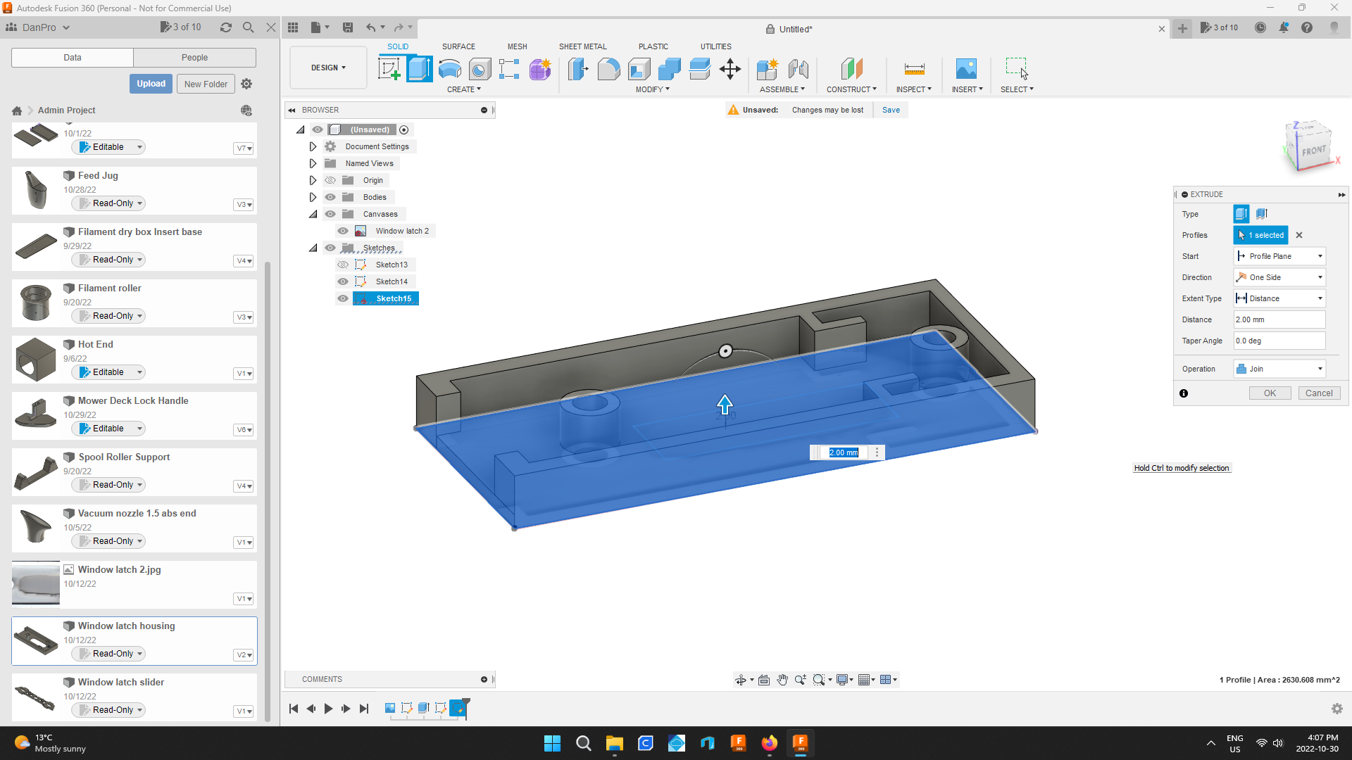
Now click on the body and select extrude.
Extrude the body 2mm then hit enter.
Cut Out Square Actuator Hole
.png)
.png)
.png)
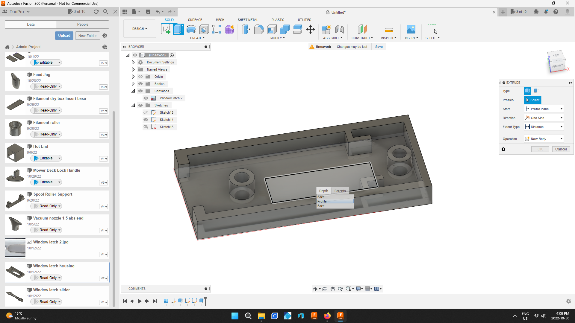
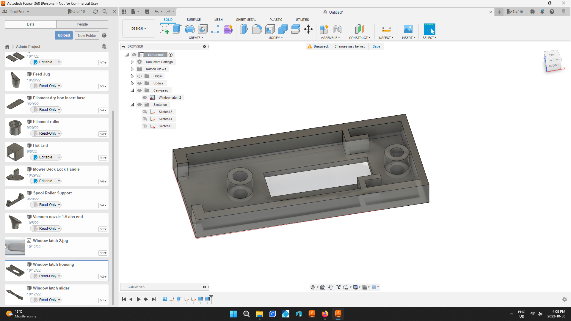
Click and hold the left mouse button in the centre of the part.
When a menu of choices appears choose profile.
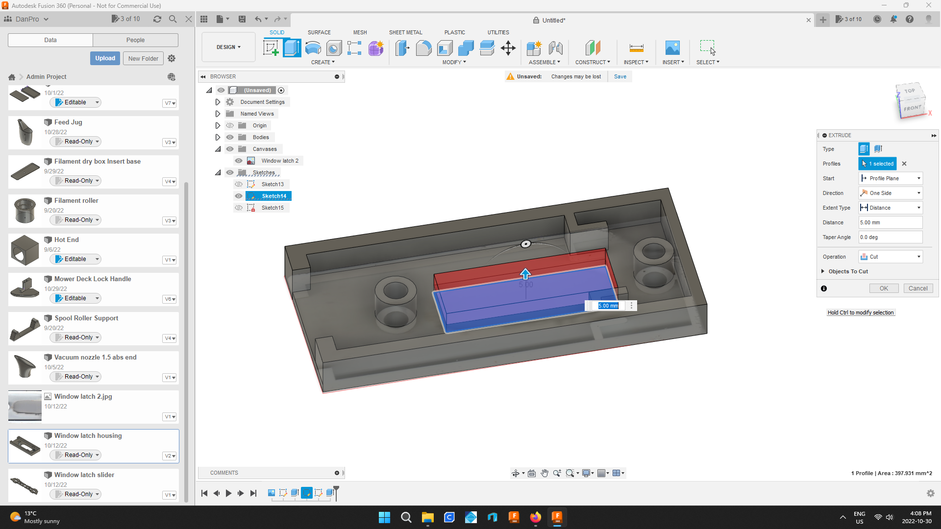
This will select the rectangle drawing.
Select the extrude tool and use it to cut out the rectangle.
Cut Out Mounting Holes
.png)
.png)
.png)
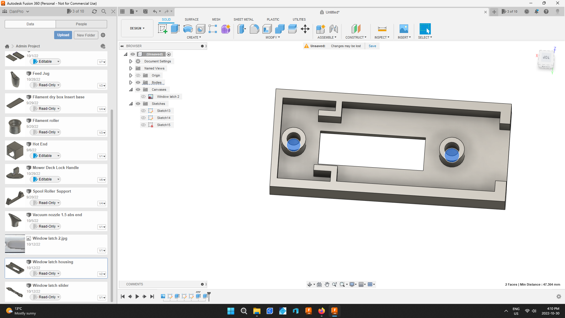
While holding ctrl select the bottoms of both mounting holes.
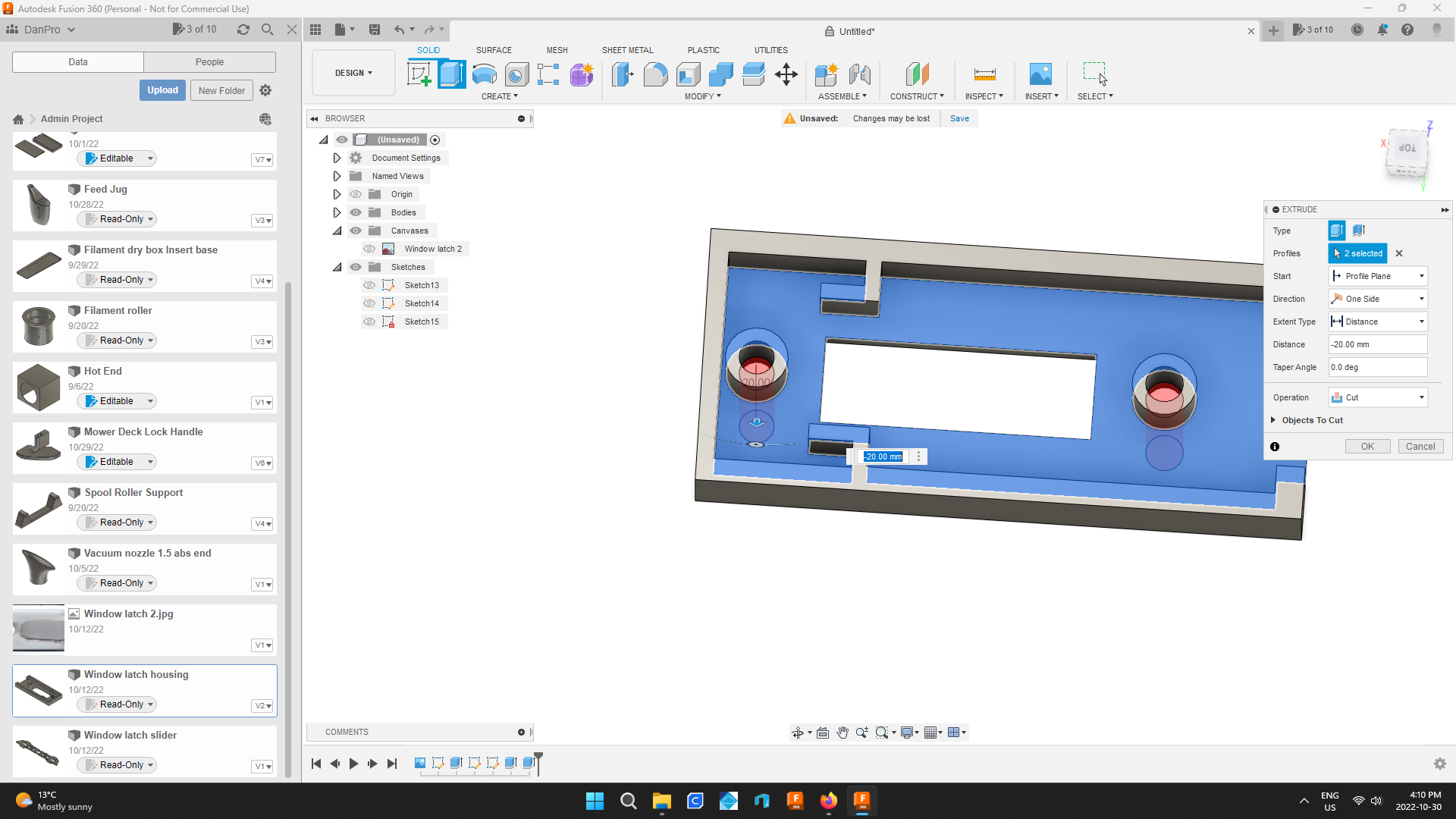
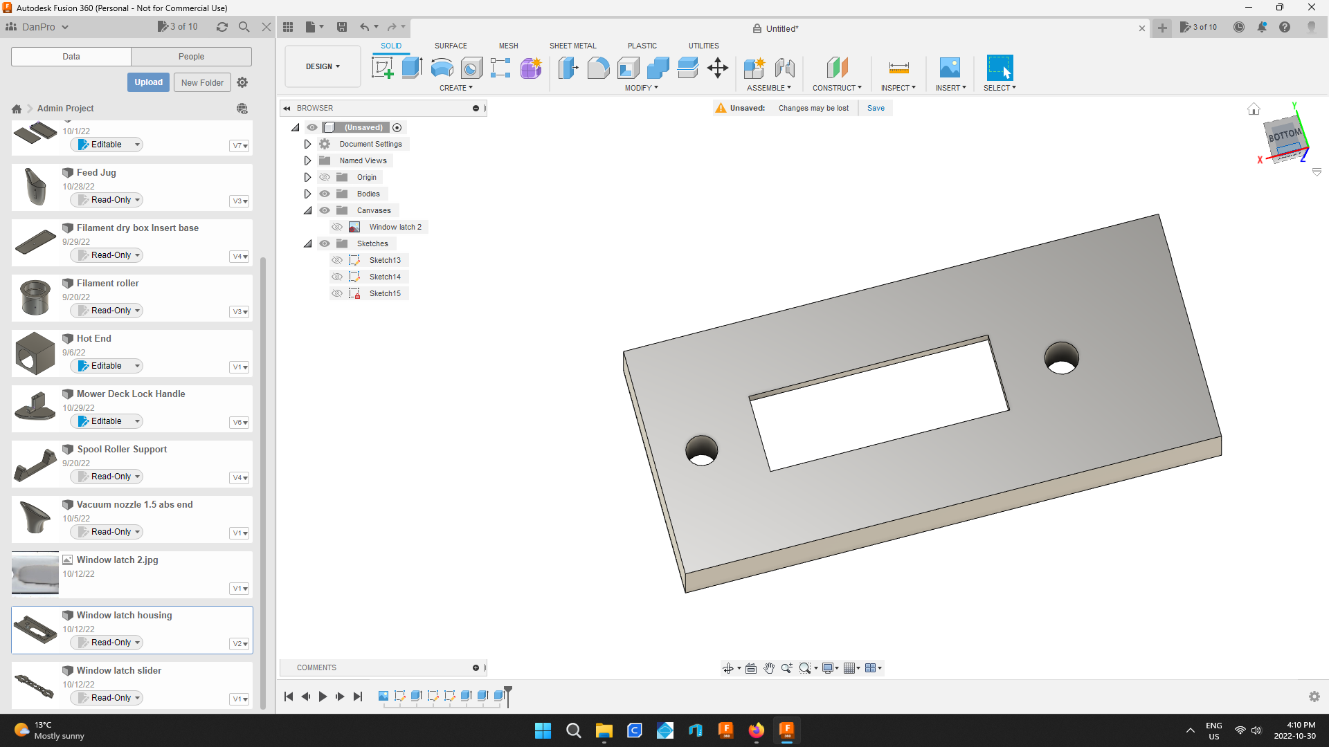
Use the extrude tool to cut through the bottom creating a through hole.
The rough part is now complete.
Fillet the Ends of the Actuator Hole
.png)
.png)
.png)
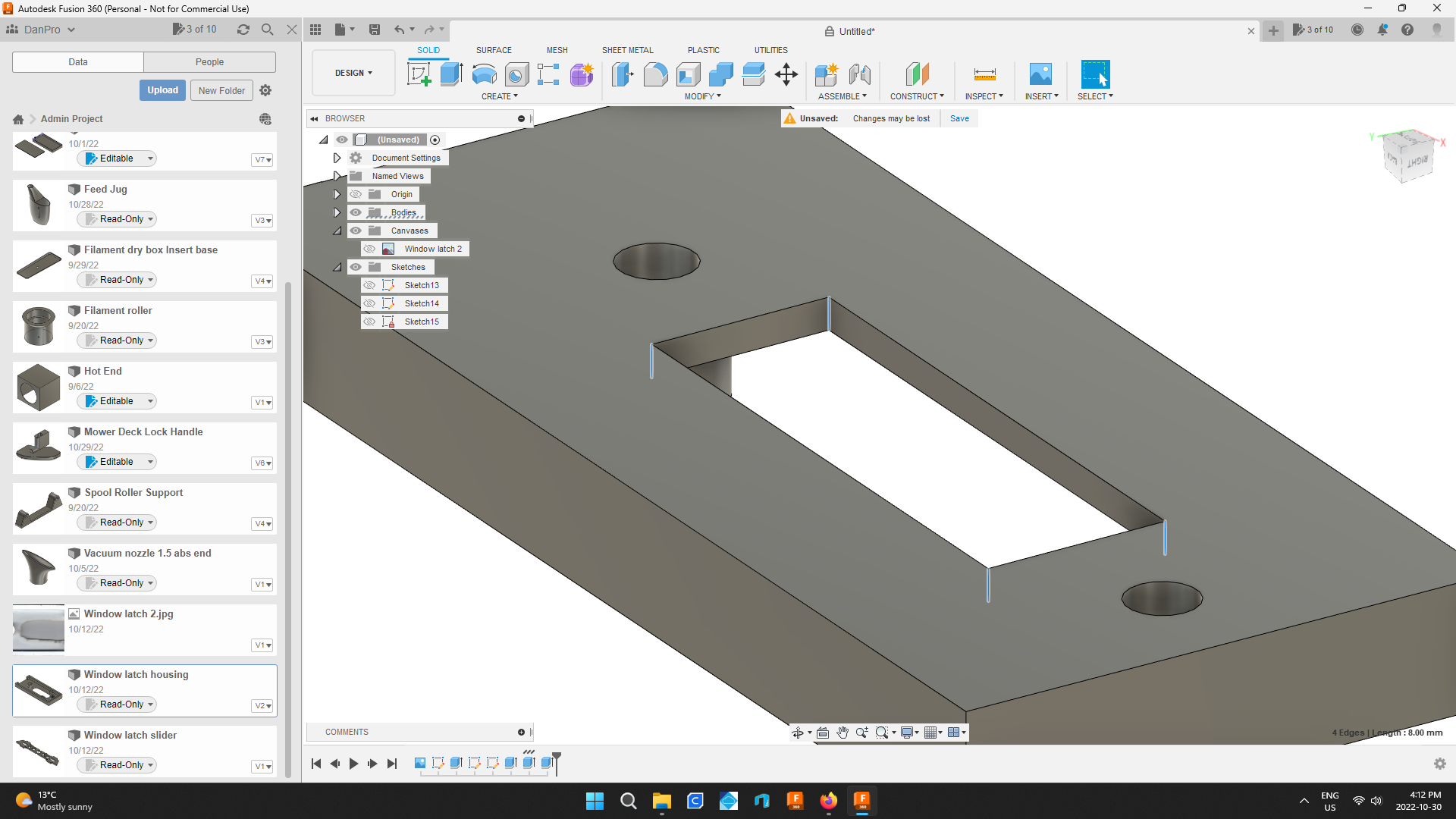
Select the four vertical edges of the rectangle using ctrl and the left mouse click.
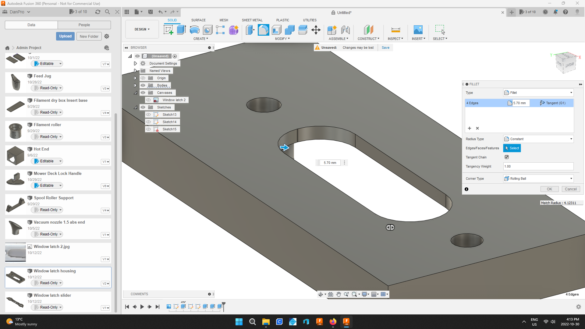
Use the fillet tool to round out the ends of the hole.
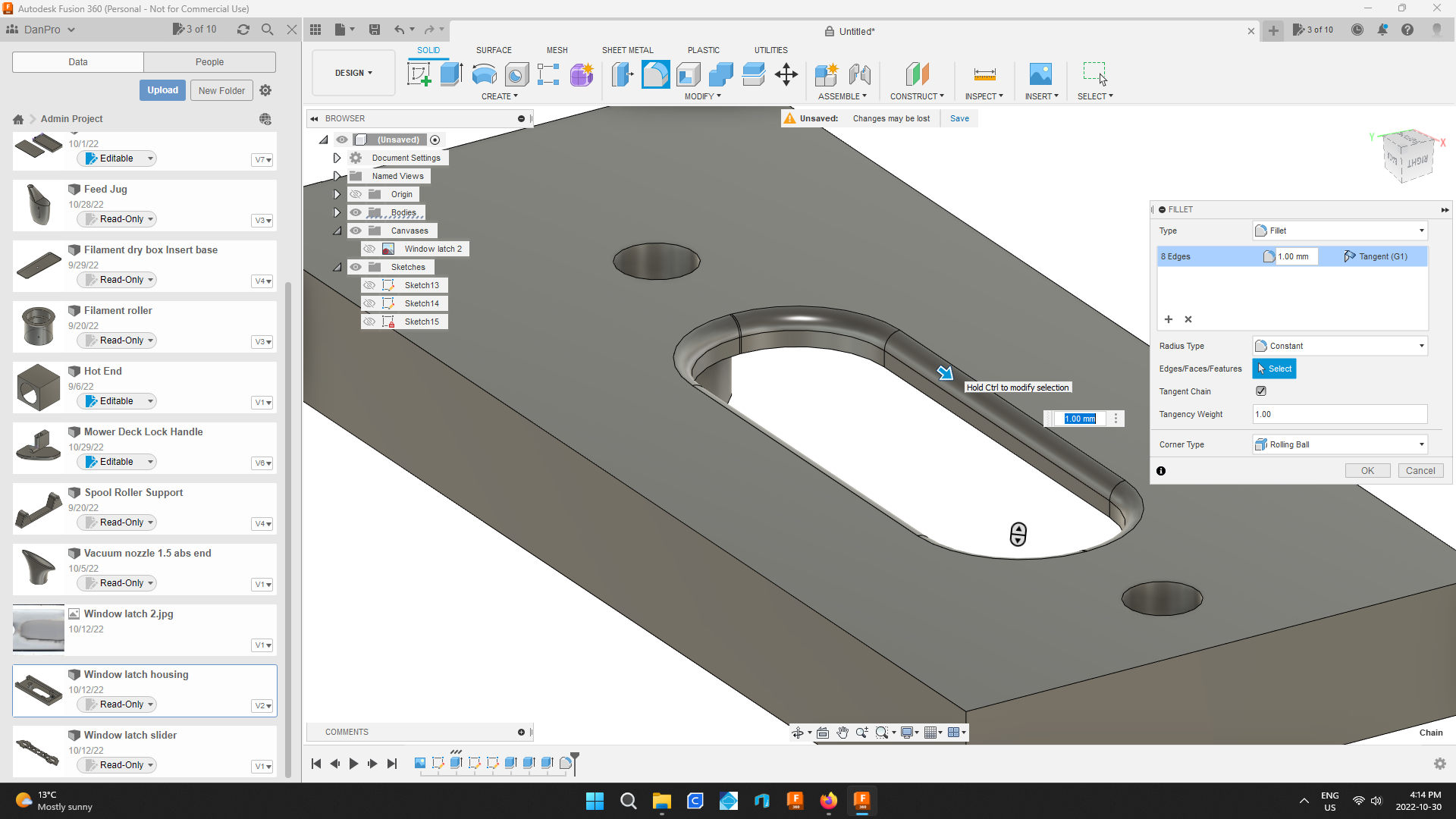
Fillet the edges of the hole now as well.
Filleting gives the part a nice finished look.
The size of fillet is a judgment call.
The part would be functional without them.
Countersink Mounting Holes
.png)
.png)
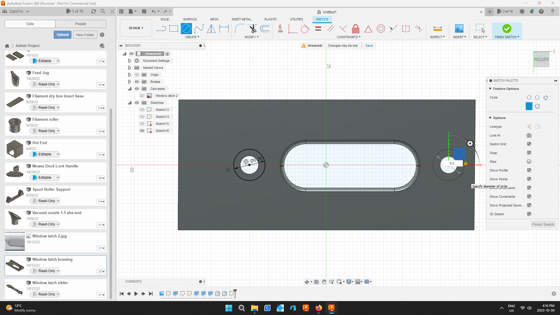
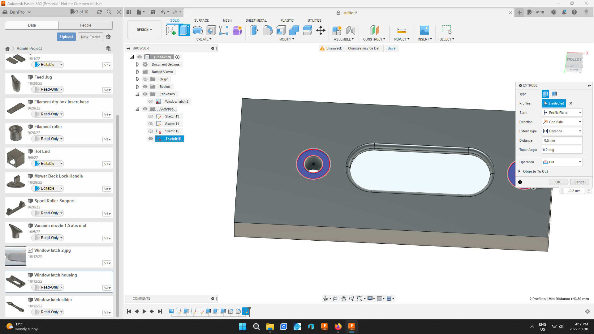
Countersink the mounting holes by sketching circles and extruding a cut into the face of the part.
Use the Fillet Tool and Round Out External Edges
.png)
.png)
.png)
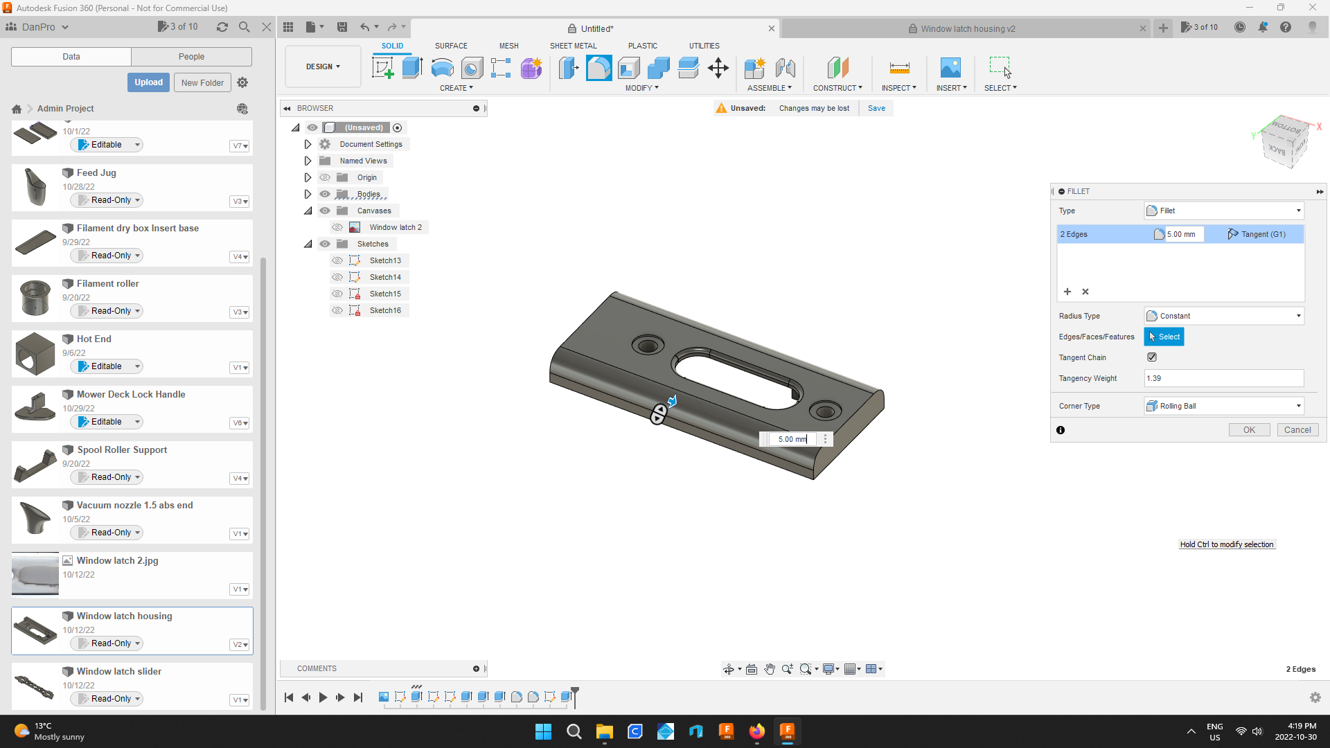
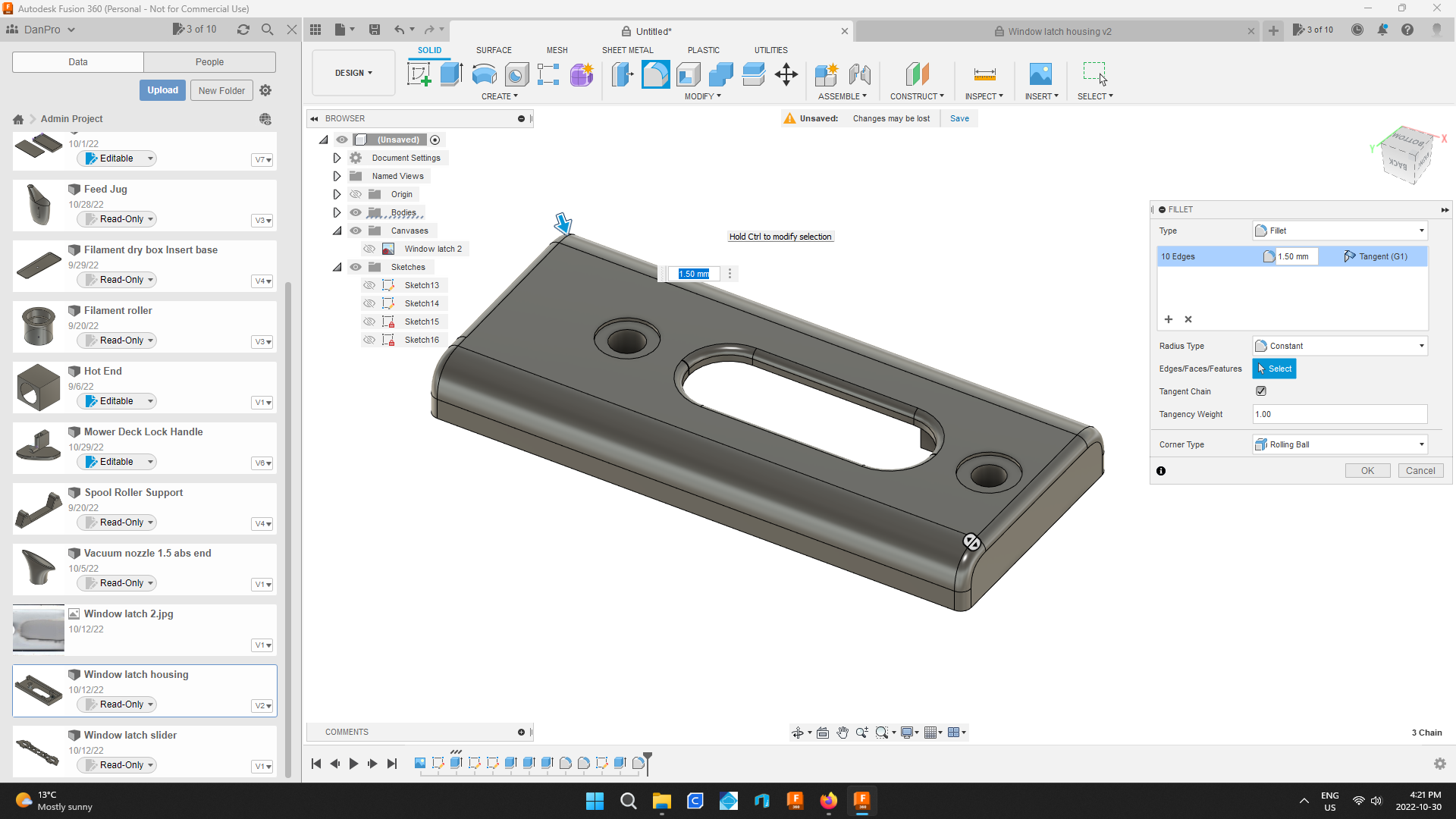
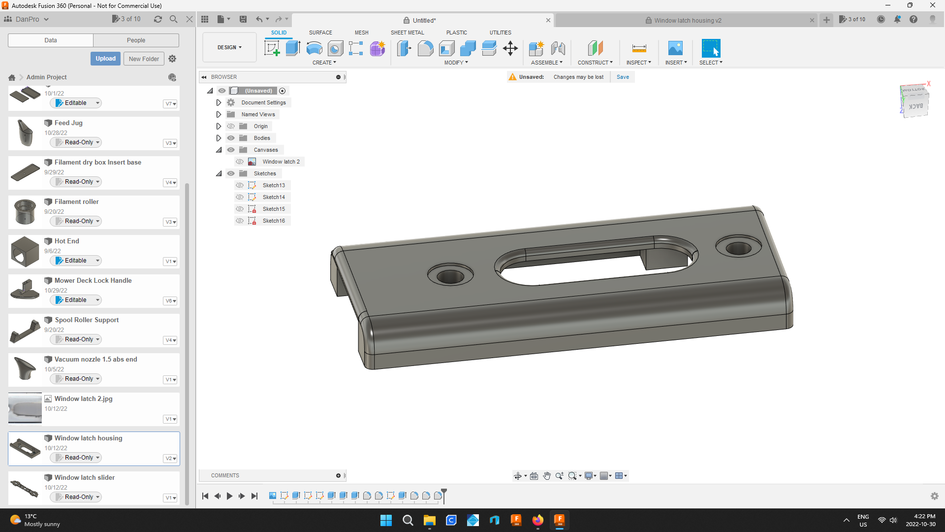
Again filleting is just for looks not function.
I want the parts to look nice when I show off my handiwork.
Use What You've Learned
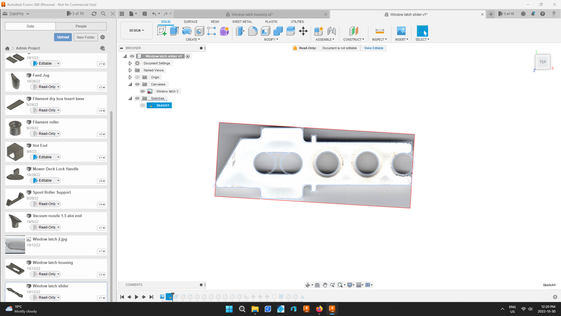.png)
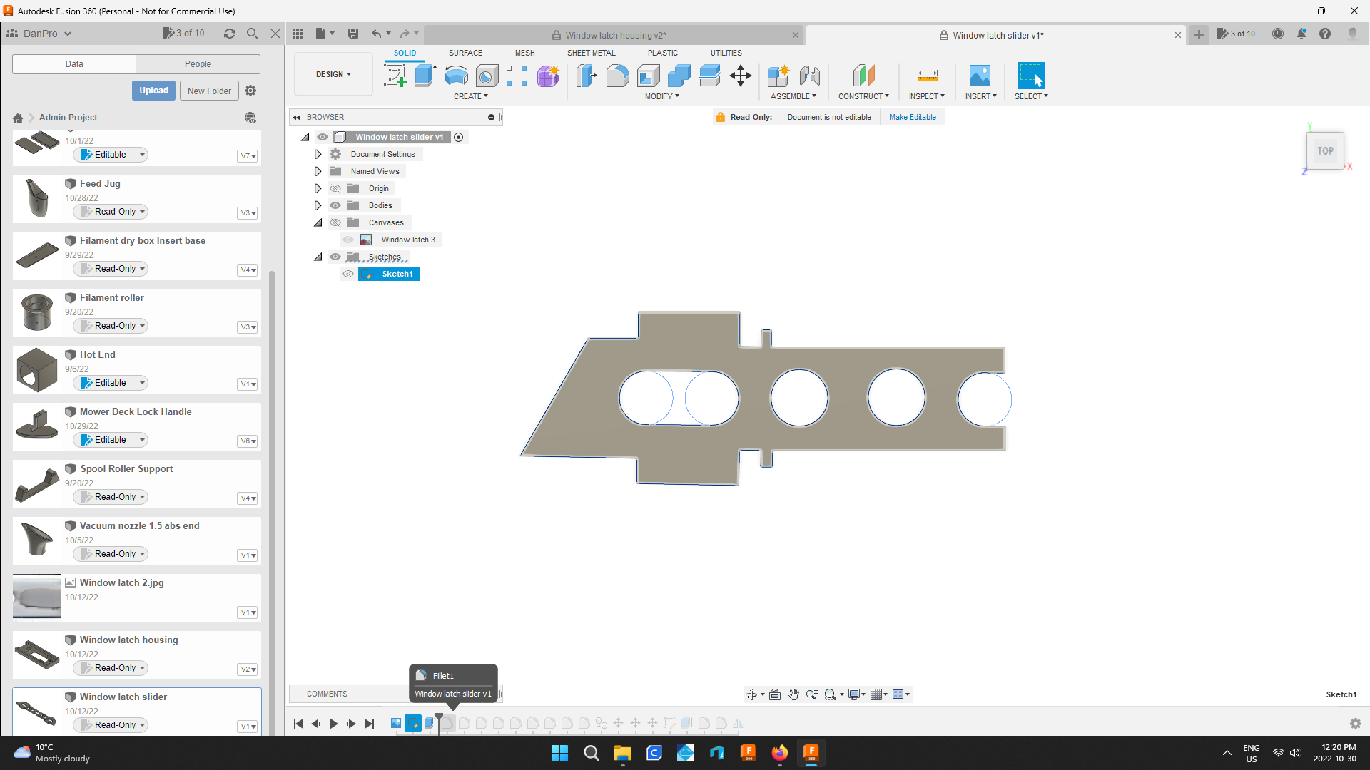.png)
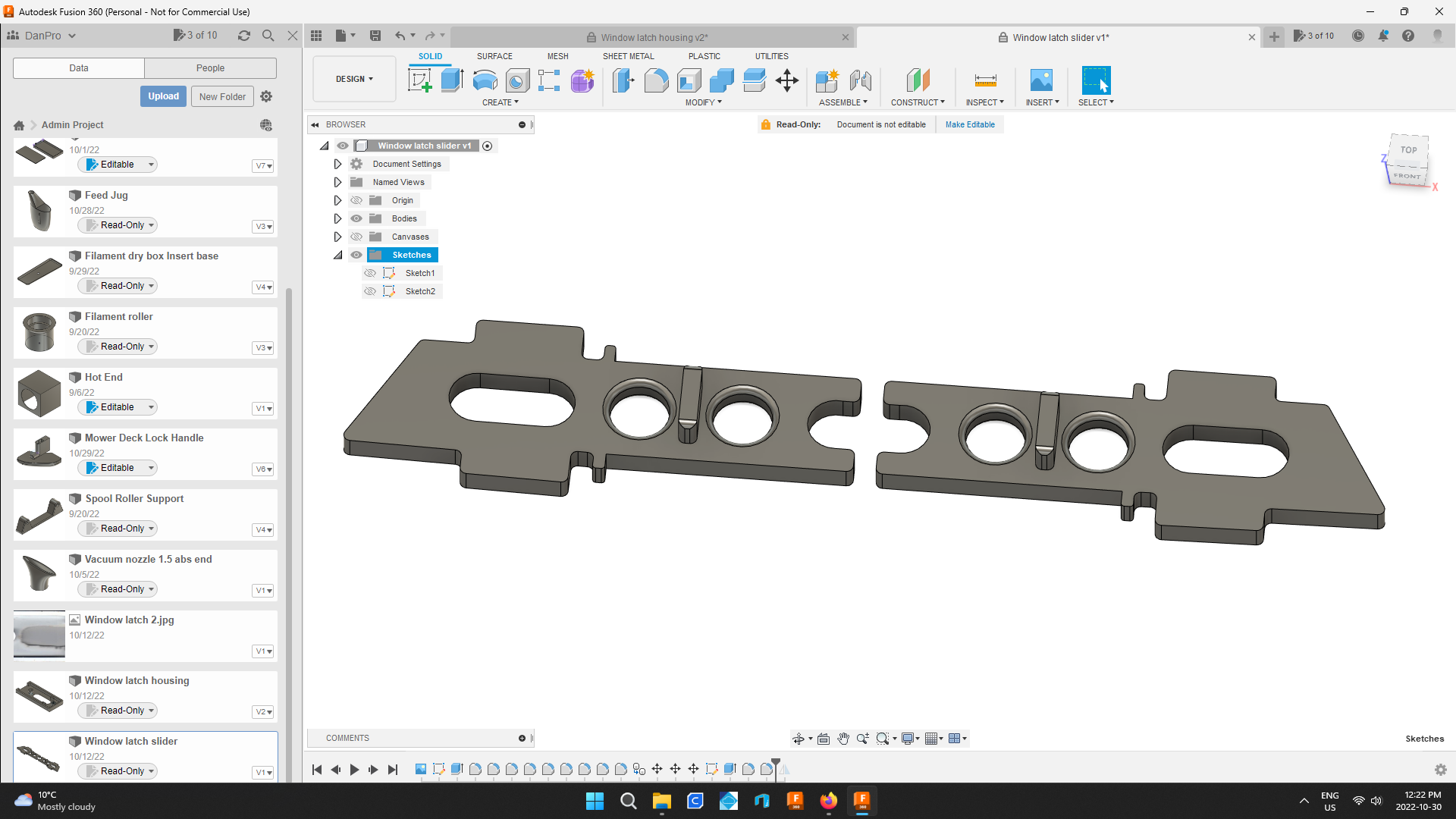.png)
Now using these techniques create the inner piece.
The only thing I've not covered already is how to use the mirror function.
I'm sure you can figure it out.
If not scan the part from the other side of the window and start again from the beginning..
Prepare to Print
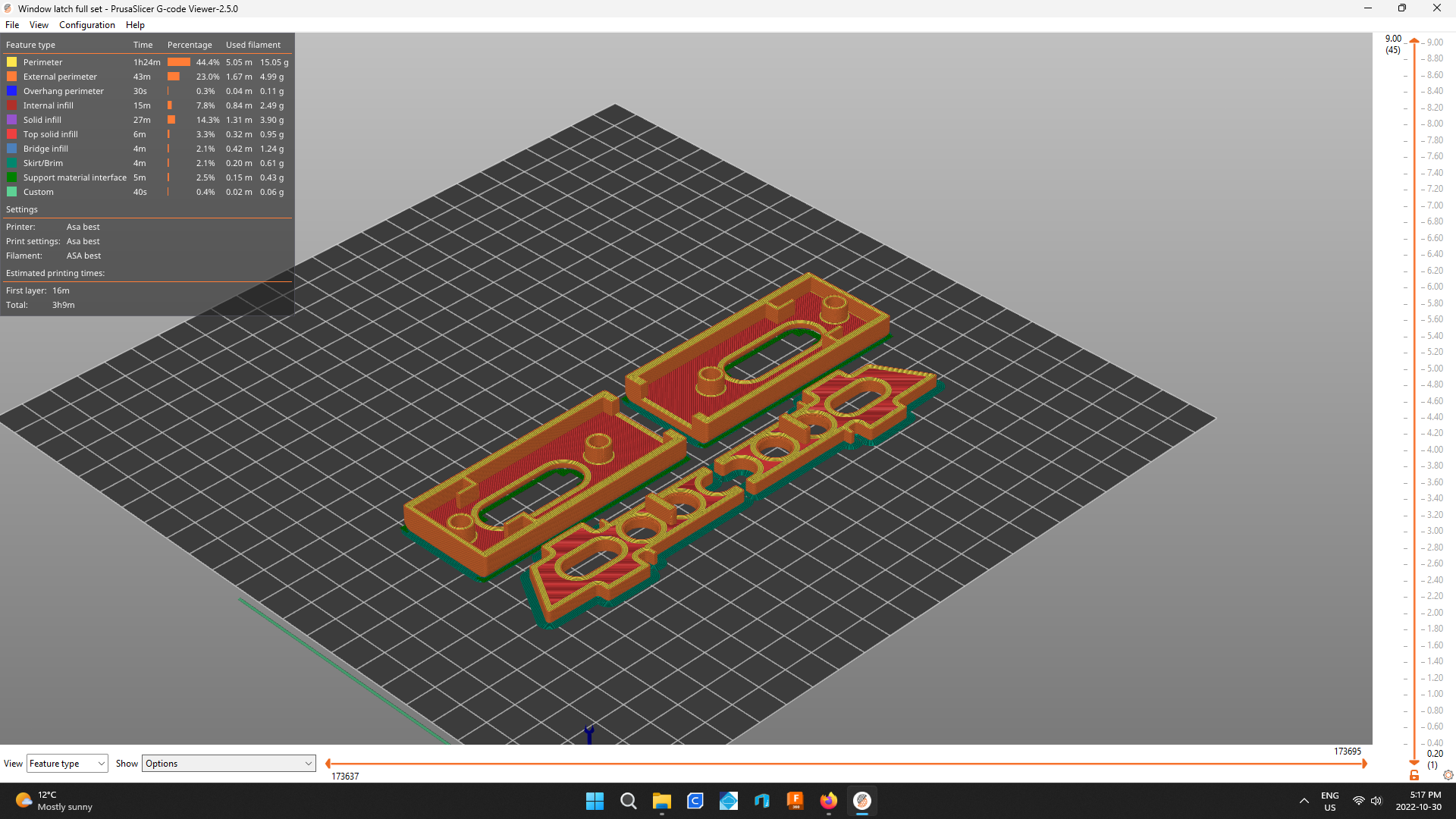.png)
I print one set at a time.
It takes just over 3hrs
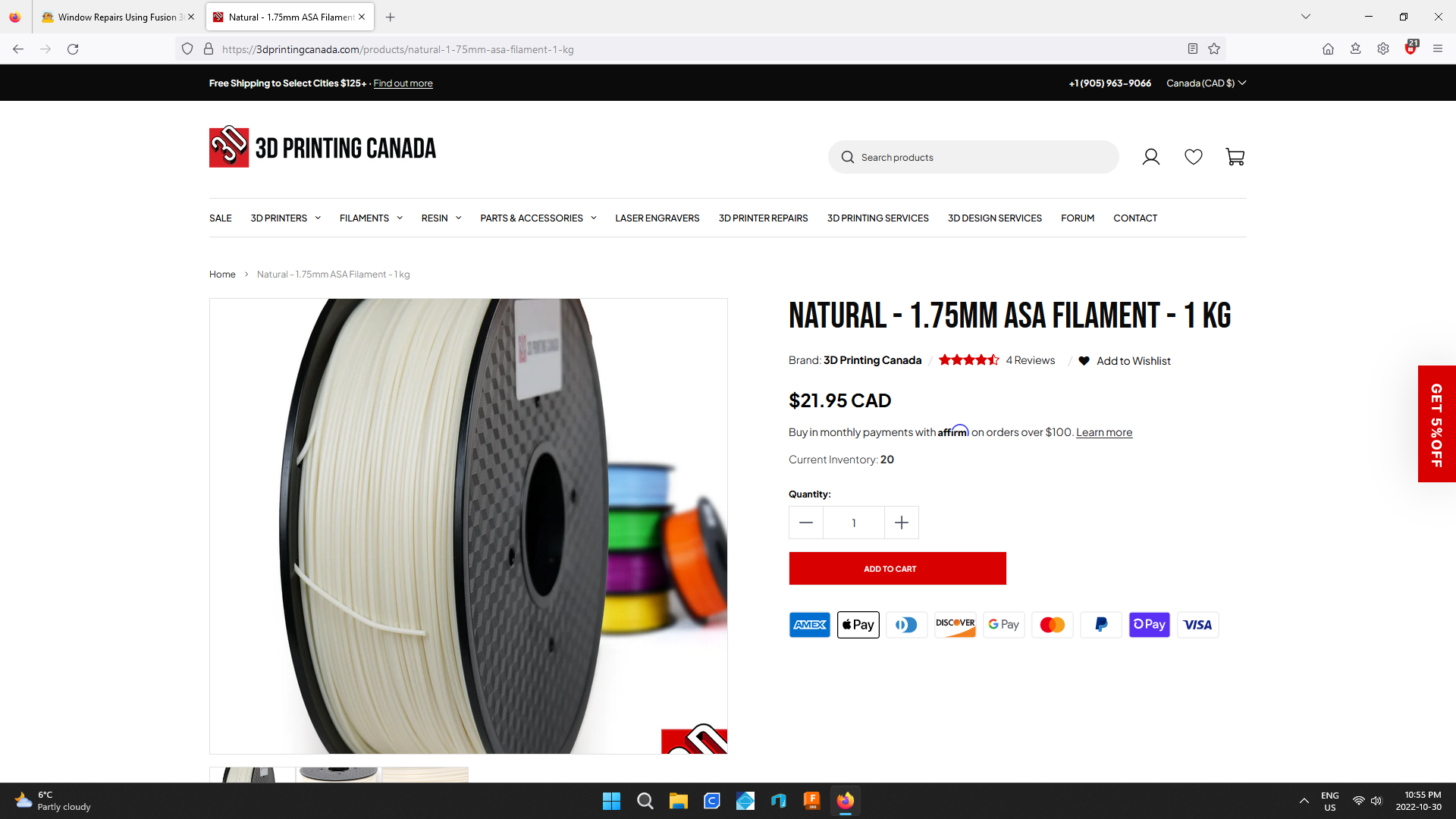
I use ASA filament purchased from 3d Printing Canada.
ASA is UV stable.
I'm hoping these will outlast the previous parts.
Thanks for Reading, Happy Instructing
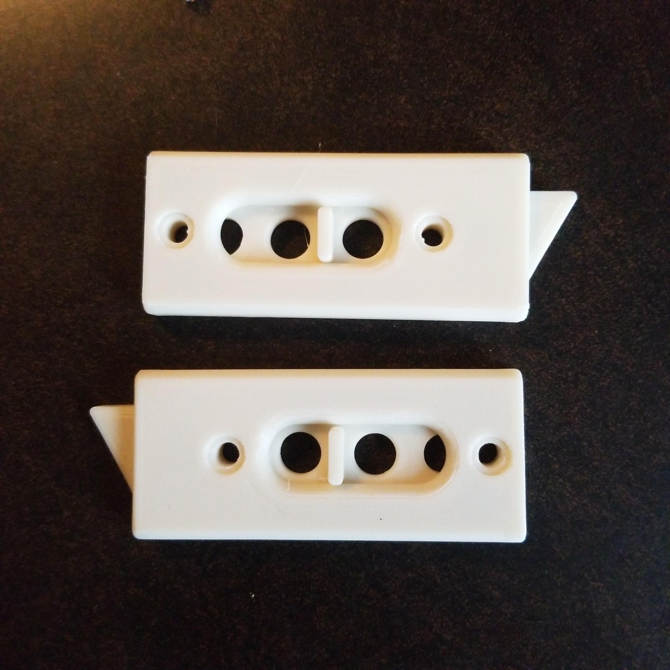
To make all the sets I needed, I used about $15 in filament.
I love it when I create practical 3d prints that save me money.
You can find some of my other creations on Instagram https://www.instagram.com/pelham3d/
A big thank you to Autodesk for allowing personal use of Fusion 360 !