Wifi Photobooth With a Raspberry Pi
by andyk75 in Circuits > Raspberry Pi
32030 Views, 270 Favorites, 0 Comments
Wifi Photobooth With a Raspberry Pi
This project is about a photobooth totally controlled and operated by just one raspberry pi. You can even operate it with a 12V car battery for quite a while.
What you can do with it:
Set it up as a normal photobooth for marriages, birthdays or just for fun.
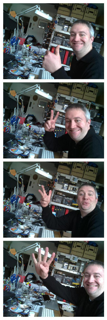
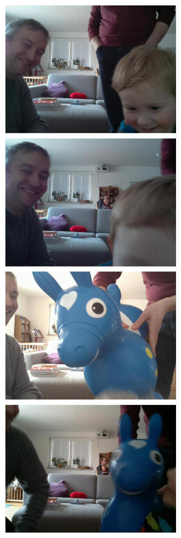
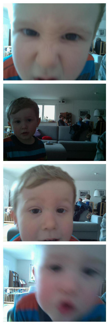
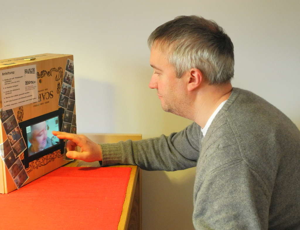
When someone touches the screen, a countdown starts and takes 4 pictures with the 3s countdown each.
After that the four pictures are combined into one and a QR-code is generated for the download of the picture.
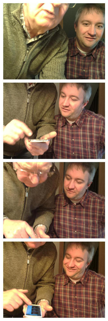
Your guest can then connect to the wifi of the photobooth itself and download the picture-strip they just shot.
At the end of the day you can have a look at all the pictures on the webserver and download them or put them up on a cloud for further sharing.
No paper is wasted for tiny pictures and everybody (with a smartphone or a laptop) can immediately take home their pictures or post it somewhere!
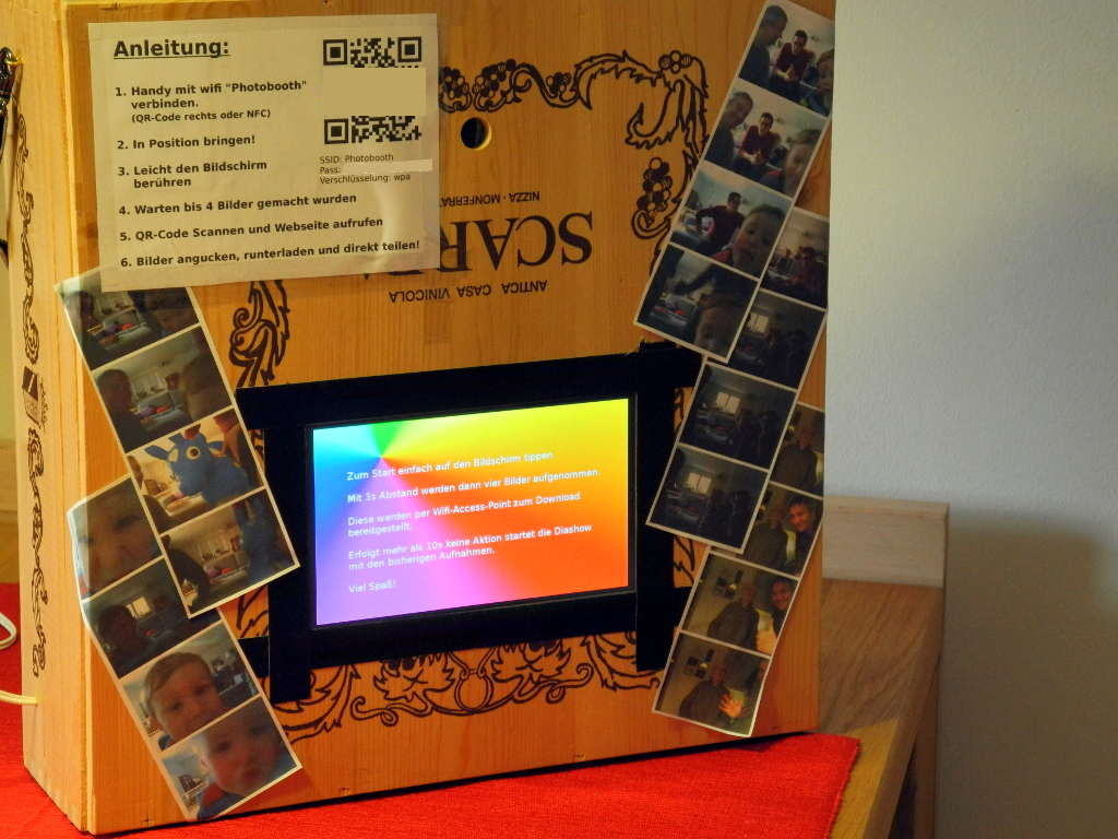
If nobody uses the photobooth, a picture-show of the last taken pictures starts until someone touches the screen again! :-)
Mechanical Setup
What you need to build this is:
- a normal raspberry pi B+ (30€)
- a 16GB micro-SD card (8€)
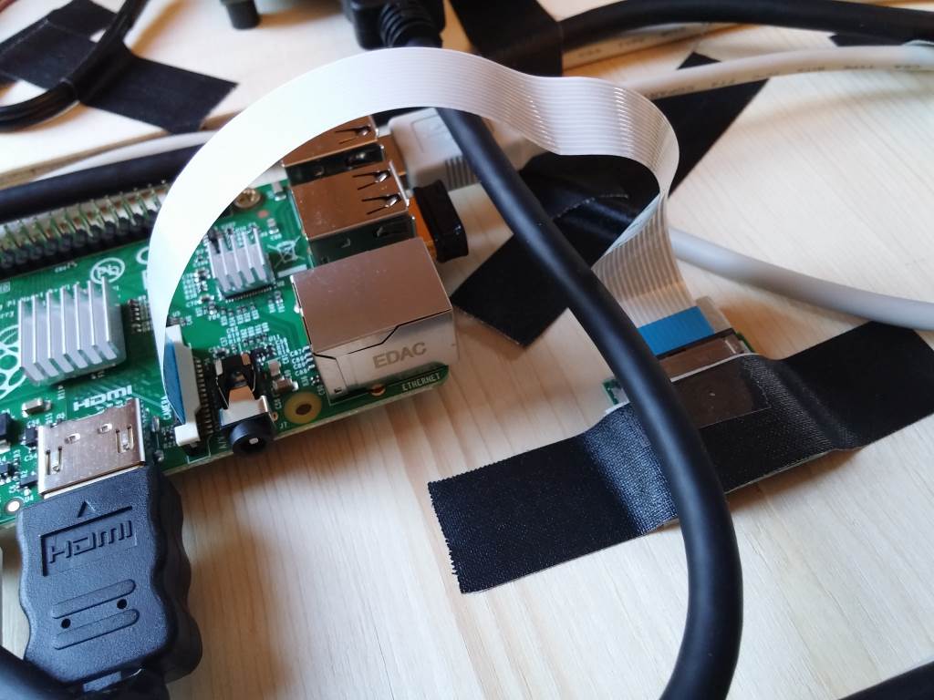
- the raspberry pi camera (25€)
- a wifi dongle for the raspberry pi with Access Point support (10€)
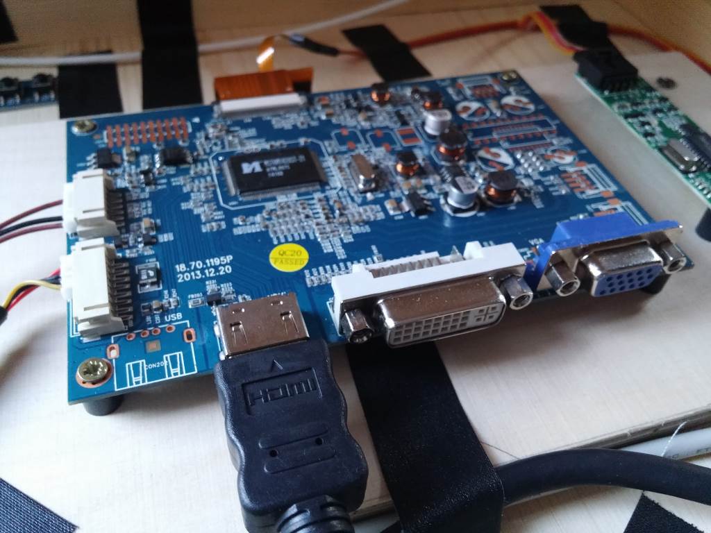
- a 7'' touch-screen display with HDMI-input (mine is from pollin, 55€)
- a 12V 2A power-supply (10€)
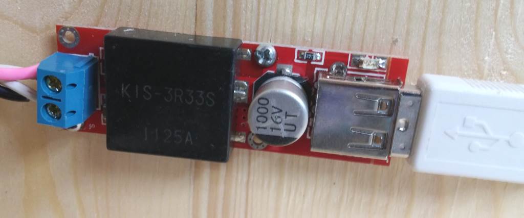
- a 5V 3A step-down module (search for KIS 3R33S) (5€)
- an old wooden box or something similar
- a few small wood-screws and some tape
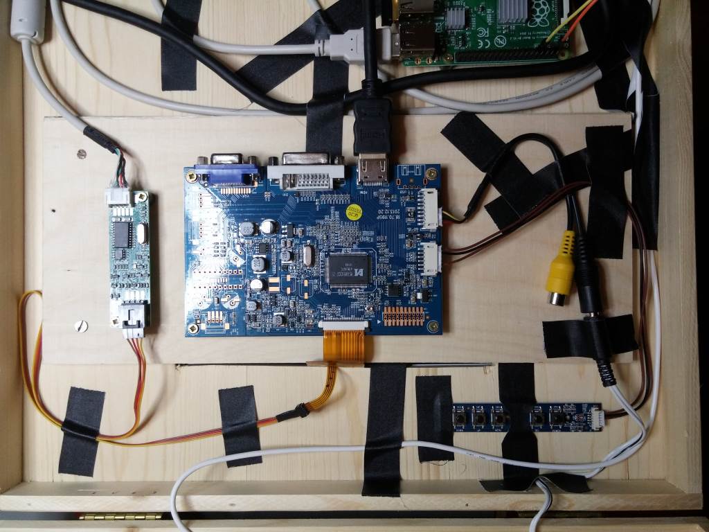
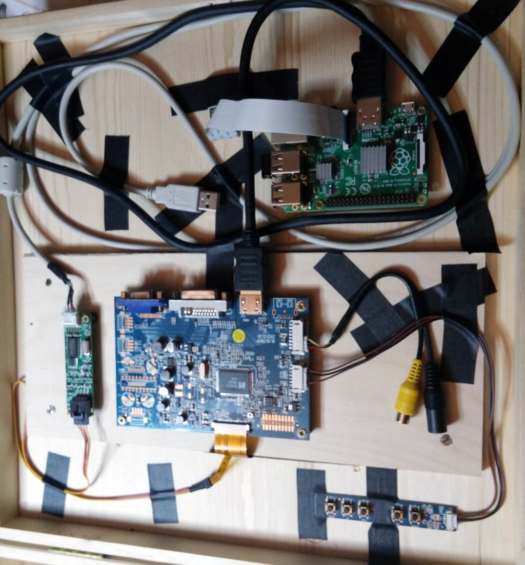
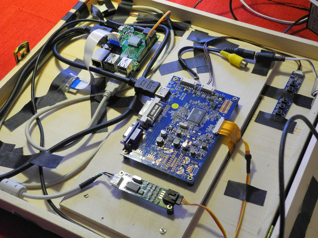
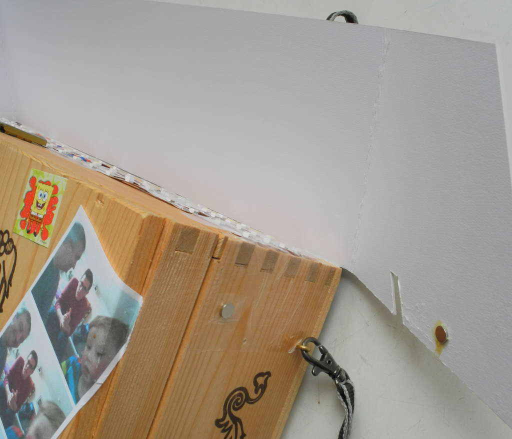
I was lucky, because the wine-box I used for this project has a very thick cover. All I needed to do was cut a hole for the touchscreen and back it up from the inside with a piece of wood. To prevent the touchscreen to fall out of the front I used a bit of sticky tape.
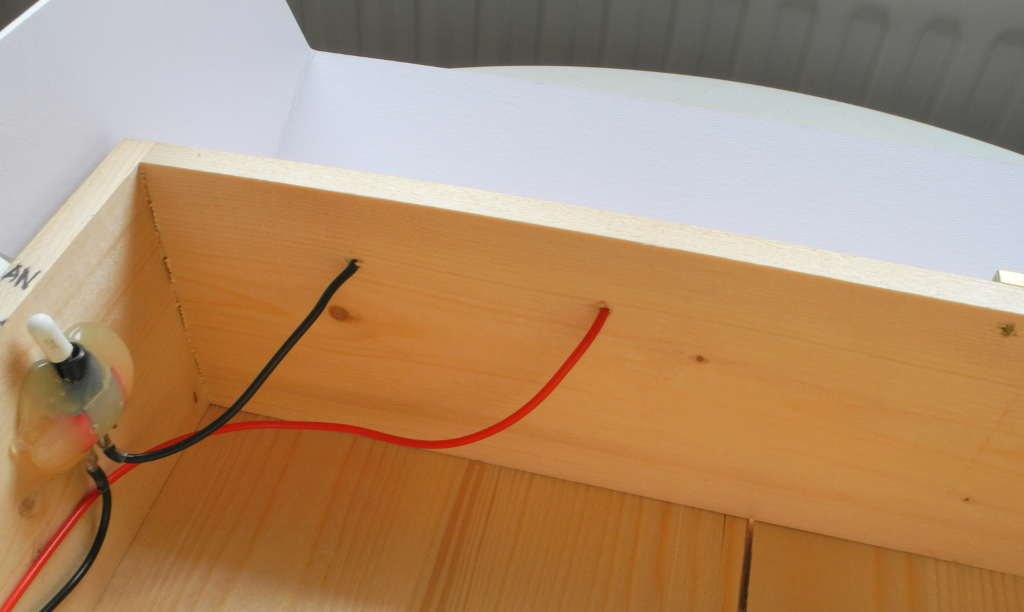
All the other things are screwed on the inside of the box. It's up to you to arrange them and make it fit.
The 12V power is for the touchscreen-display which needs up to 400mA. The KIS 3R33S step-down module converts the 12V to a 5V output for the raspberry pi with a better efficiency than a simple 7805-linear-controller.
Run Raspi-config for Initial Setup
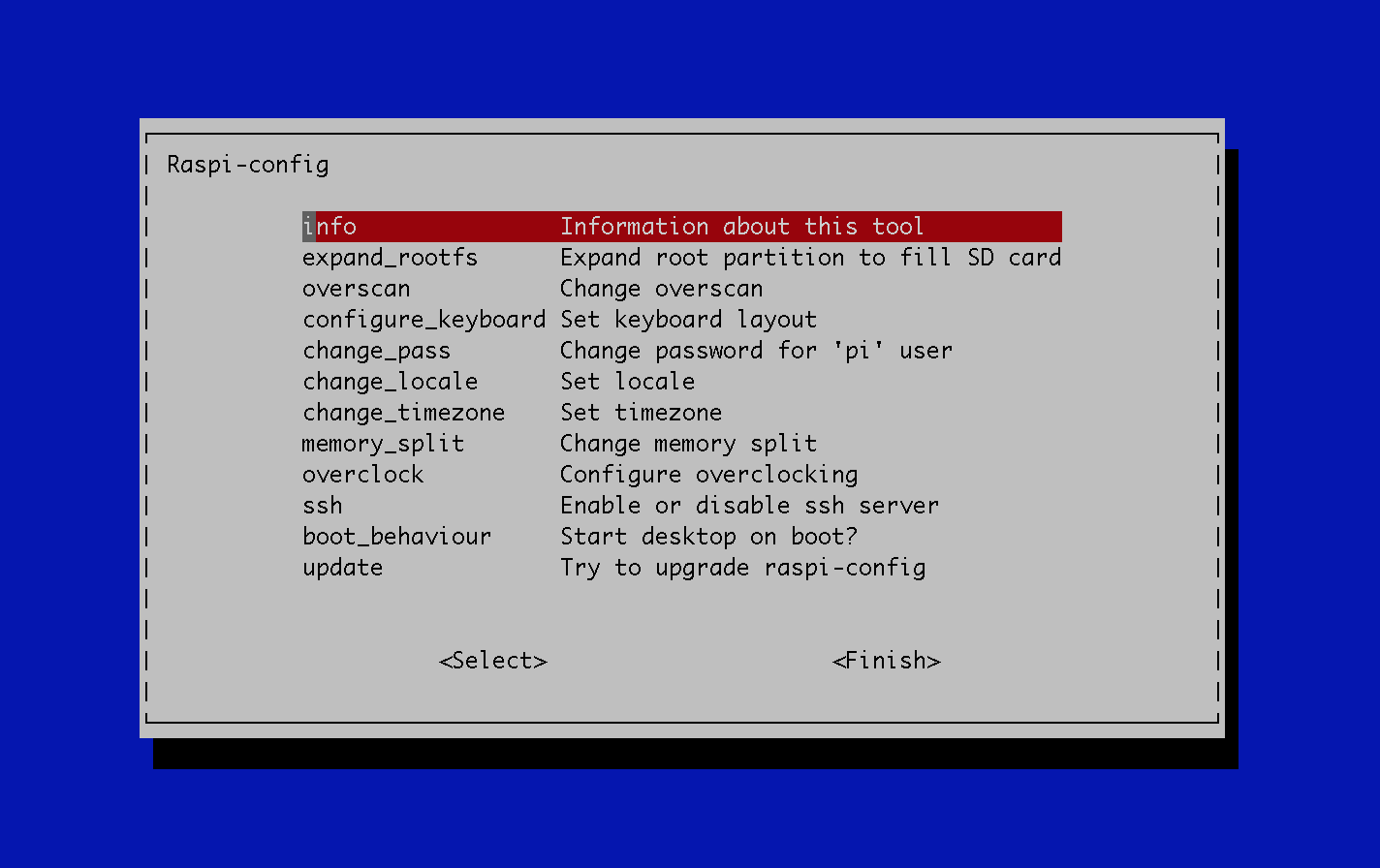
Start up the pi and log in. Then run
sudo raspi-config
First of all: CHANGE THE DEFAULT PASSWORD!
Then you can adjust:
- country-settings, keyboard-layouts and so on
- expand the file-system to the maximum of your card
- set the hostname
- enable the camera support
- adjust overclocking parameters
- and much more.
Just click ok to reboot when you are finished.
Update the Raspbian

Now you can connect your raspberry with a LAN-cable and log in via ssh. I find this much more convenient than working on a separate screen.
Most of the time I have the ssh-shell and the browser side by side and you can very quick copy and paste the commands to the shell!
First of all we want to make a complete update of the system. The wolfram-alpha-engine which is part of the raspbian is quite big and for this project we don't need it, so we remove this big package from the pi with
sudo apt-get remove wolfram-alpha
after this command finishes you can do:
sudo apt-get update
sudo apt-get upgrade
sudo apt-get dist-upgrade
Now you are starting out with the latest version.
Raspberry Pi Access Point Setup


Now you might want to start setting up the wifi-accesspoint, or you can do it in the end. That doesn't matter.
While you are still setting up the photobooth you can always use the LAN to connect the Raspi to you lokal network.
To set up an access point you need to have the hostapd-service and a DHCP-server. The first service handles the access-point itself and the dhcp-server asigns IP-adresses to the clients that log into the access point. Because we don't want to route the clients to the internet via LAN we don't need to change any routing-tables or other stuff. But you can do it if you want.
I used this setup because my wifi-stick has the RTL8188CUS chip inside:
http://blog.sip2serve.com/post/48420162196/howto-setup-rtl8188cus-on-rpi-as-an-access-point
Or you give this a try http://learn.adafruit.com/downloads/pdf/setting-up-a-raspberry-pi-as-a-wifi-access-point.pdf
or this http://elinux.org/RPI-Wireless-Hotspot
There are so many wifi-sticks out there and so many good tutorials that all write the same, I decided that I don't have to rewrite this again. Keep an eye on the date of a tutorial! Many things have grown much easier than back in the days and if you use the latest software you should use the up-to-date tutorial for it!
To find out which chip is inside your wifi-stick use:
sudo dmesg -c # this prints out all systemmessages and deletes them.
Now plug in the stick and run
dmesg
You should see something like this:
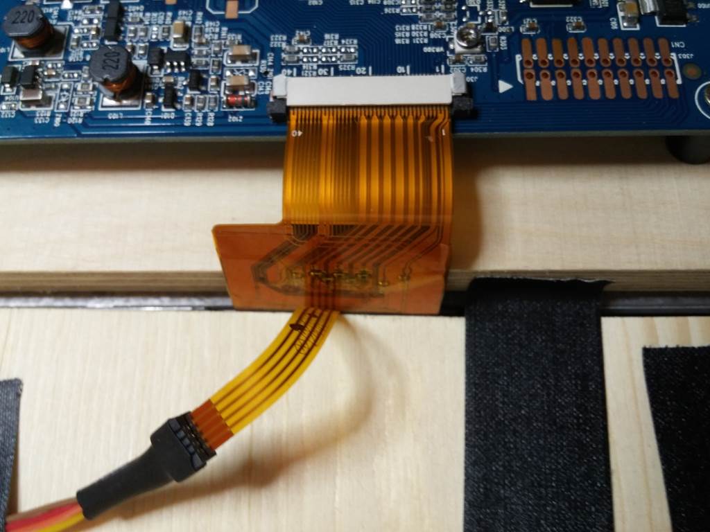
Activate the Touchscreen

If you have put everything together in the first step (mechanical setup) the chances are good that the screen is already working.
With the screen I have, there are several issues:
- First of all the native resolution is 1024x600. This is not common to the raspian and I had to adjust the settings to fill the screen.
- Second there is no native touchscreen support in the kernel that is in the raspbian. So we have to fix this.
Log in to the raspberry pi and go to /boot.
Then make a backup and edit the file: config.txt
Add or uncomment and change the following lines:
overscan_left=-32<br>overscan_right=-32 <br>overscan_top=-20
overscan_bottom=-20<br><br>hdmi_force_hotplug=1<br><br>framebuffer_width=1024<br>framebuffer_height=600<br><br>hdmi_mode=19
First of all hdmi_force_hotplug=1 activates the HDMI-output. No matter if there is a display or not. If you see a picture, you don't need this.
The framebuffer_width and height are adjusted to fit the native size of the panel used.
Because the frame itself hat black surroundings I adjusted the overscan-parameters with negative values. If your screen seems to be bigger than the display, try to use positive values.
hdmi_mode=19 means the output is 720p over HDMI. For further information about all the settings in this file look at this link: http://elinux.org/RPiconfig
With the statement:
disable_camera_led=1
You can disable the annoying red led on the pi camera.
Compile a New Kernel for Touchscreen-support
When you want to use the touchscreen you have to compile the kernel, because in the standard-kernel there is no touchscreen-support.
UPDATE: I wrote this chapter some time ago and in the current version of the raspbian image there is already a Touchscreen-driver included. so just try and skip this part. But I didn't want to delete it, because it might be useful for new unknown touchscreens or other hardware you need to compile a kernel for!
HOW TO COMPILE A CUSTOM KERNEL:
There are a lot of touchscreen controller out there! If you have the same controller as I have, you can use my kernel. In any other case you have to compile it by yourself.
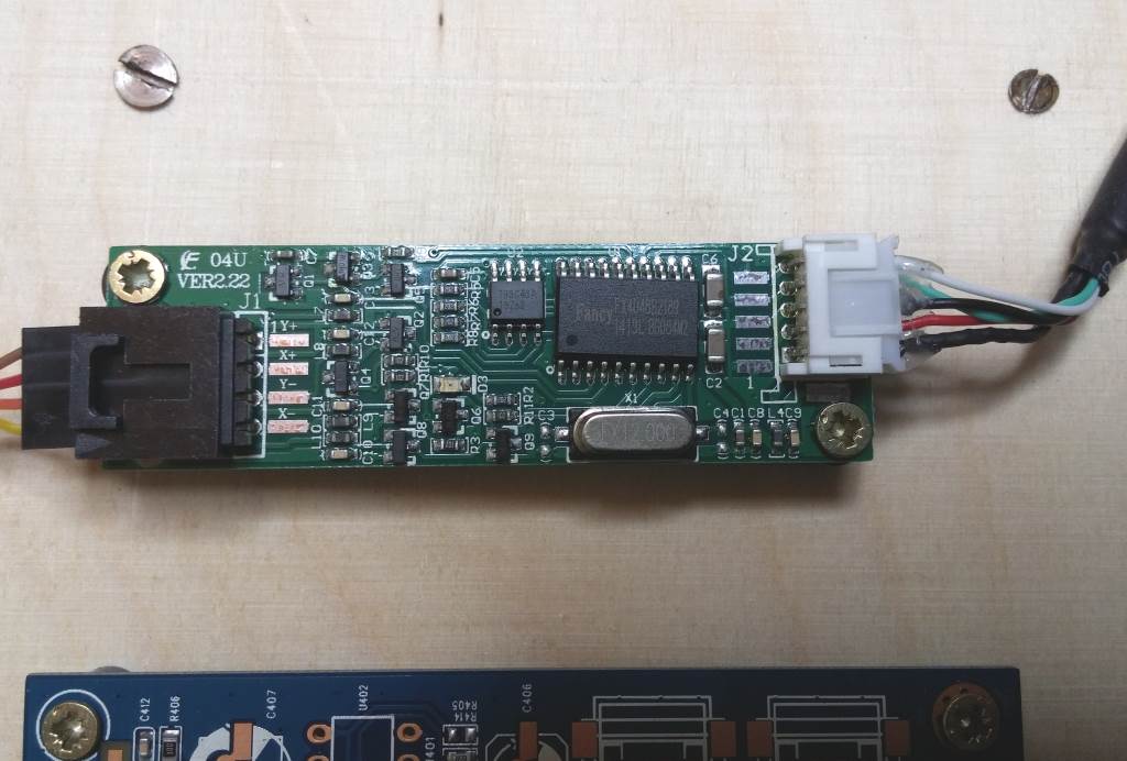
How to find out which controller you have do:
sudo dmesg -c >dmesg.bkplog
this will save the system-messages from bootup into the file "dmesg.bkplog" and clear the system messages. You will see no output. The backup is just to make sure you have it when you need it. Maybe there have been some fails during boot or other crazy stuff, it is all in this file now! If everything is o.k. you can delete it again. Just wait a second until a new line in the console appears. Now plug in the usb-cable from the touch controller and run
sudo dmesg >touch.log
This will save the system-messages that you touch-controller provoked into the file touch.log.
You can now view the content of this file with
cat touch.log
It might look like this:
[  202.843625] usb 1-1.5: new low-speed USB device number 5 using dwc_otg<br>[  202.949360] usb 1-1.5: New USB device found, idVendor=0eef, idProduct=0001
[  202.949400] usb 1-1.5: New USB device strings: Mfr=1, Product=2, SerialNumber=0
[  202.949418] usb 1-1.5: Product: Touch
[  202.949434] usb 1-1.5: Manufacturer: eGalax Inc.
[  202.972591] input: eGalax Inc. Touch as /devices/platform/bcm2708_usb/usb1/1-1/1-1.5/1-1.5:1.0/0003:0EEF:0001.0001/input/input0
[  202.975579] input: eGalax Inc. Touch as /devices/platform/bcm2708_usb/usb1/1-1/1-1.5/1-1.5:1.0/0003:0EEF:0001.0001/input/input1
[  202.977143] hid-generic 0003:0EEF:0001.0001: input,hidraw0: USB HID v1.12 Pointer [eGalax Inc. Touch] on usb-bcm2708_usb-1.5/input0
[  203.027388] usbcore: registered new interface driver usbtouchscreen
We can see in line 6 and 7 that the controller is recognized as an Input of "eGalax Inc. Touch". There are in fact two inputs and you have to try out which one works. I don't know why this is so.
To know if the new kernel really works type
uname -a >kernelold.txt
This will write the information about the current kernel to a file called kernelold.txt.
To install the new kernel just download the tar.gz which sticks to this step. You might need to rename it to kernel.tar.gz and then unpack it on your raspberry.
Now make a backup of the original kernel and move the zImage-file to /boot/kernel.img
sudo mv /boot/kernel.img /boot/kernel.img.bkp<br>sudo mv ./zImage /boot/kernel.img
The make a backup of the /lib/firmware and the /lib/modules folder and move the unzipped folders to /lib
sudo mv /lib/firmware /lib/firmware.bkp<br>sudo mv /lib/modules /lib/modules.bkp<br>sudo mv ./firmware /lib/firmware<br>sudo mv ./modules /lib/modules<br>sudo reboot
After reboot, log in again and type
uname -a >newkernel.txt
Now you can compare these two files and should see that the new kernel works.
If you compiled the kernel by yourself and the raspberry isn't starting up. Just mount the sd-card in some laptop or PC and delete the current kernel, firmware and modules and use the backup. You have another try...
If your touch-controller is of a different kind, just take the name and google it together with raspberry pi! Compiling a kernel is a whole instructable itself. But a good point to start on how to compile a kernel is: http://elinux.org/RPi_Kernel_Compilation or http://www.raspberrypi.org/documentation/linux/kernel/building.md
Downloads
Install Webserver
Well, for the operation we need a few more software packages.
I followed roughtly this tutorial: http://www.penguintutor.com/linux/light-webserver
For the webserver we need:
sudo apt-get install lighttpd mysql-server php5-common php5-cgi php5 php5-mysql
During the install there is a prompt request for a password. The password is for the mysql root user.
To enable the server to handle php scripts the fastcgi-php module should be enabled by issuing in the command
sudo lighty-enable-mod fastcgi-php
Then reload the server using
sudo service lighttpd force-reload
So far only root has access to the directory of the webserver. Because this is not what we want we change the directory owner and group to www-data (the user running the webserver):
sudo chown www-data:www-data /var/www
allow the group to write to the directory
sudo chmod 775 /var/www
and add the pi user to the www-data group
sudo usermod -a -G www-data pi
Now the user pi can also read and write to the directory where the webserver-content is stored.
After a reboot you can try to connect to the server by entering the ip-adress of the pi to a webbrowser.
You should see the lighttpd-default website. Gratulations!
Install Camera and Python Modules
For the camera and python-control we need
sudo apt-get install python python-dev python-imaging imagemagick
No further configurations have to be made on these software.
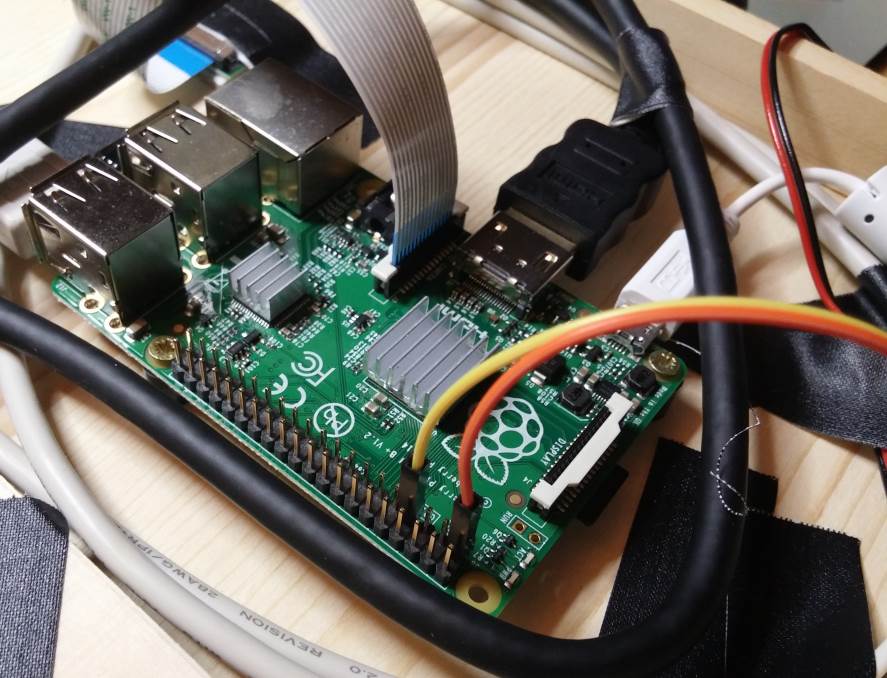
I just added a mechanical pushbutton to shut down the complete system, because once there is something wrong with the access point and the python software uses the display it gets really hard to shut down the raspberry pi safely.
So this is some kind of handy shutdown solution.
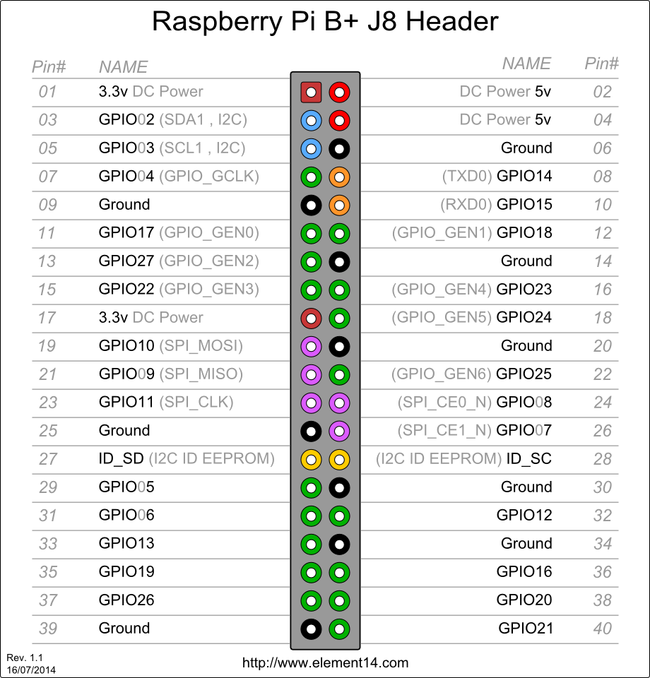
It is so easy: The pushbutton connects pin1 (3.3V) and pin7 (GPIO4) if it is pressed. In software we activate the internal pulldown for pin7 (GPIO4) and wait for a rising edge. Then the interrupt-callback is executed, which shuts down the raspberry pi.
For more information on how to use python, buttons, callbacks and everything else look here:
http://makezine.com/projects/tutorial-raspberry-pi-gpio-pins-and-python/
Install Qrencode to Generate QR-Codes
The main purpose it to share the pictures once they are taken.
And to ease this step, I decided to generate a QR-code for each set of images. So after the four pictures are taken, the software generates the strip and calculates a QR-code which leads directly to the image on the webserver.
All you need to do is call:
sudo apt-get install qrencode
That's it. If you want to learn more how to use this go to https://fukuchi.org/works/qrencode/
Add a RTC to Your Raspi
After my photobooth was finished I thought o.k. works fine. But then I began wondering where all the pictures are?
As you can see from the script, I use the current date and time as the file-name for the pictures. This is very comfortable, because you never have to mess with pictures of the same name. And all pictures are instantly in a chronological order.
But because the raspberry pi is now an access point with no connection to the NTP-server, the clock is never set again! And in this case the raspi saves the last date and time and continues from there at the next reboot. That means, each birthday or wedding the photobooth will be some days or weeks off.
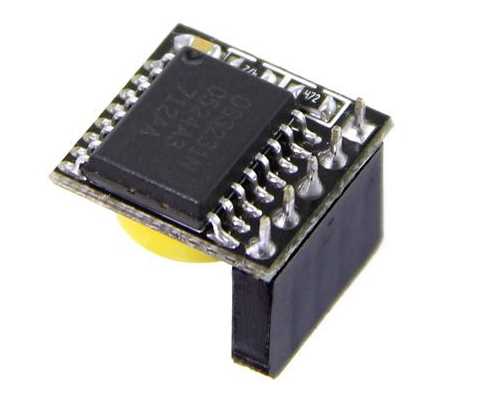
There is an easy solution for that: An hardware RTC for the raspberry pi, which is below 5€.
I chose a DS3231 that comes with a back-up-battery and a nice little connector that fits straight to the raspberry pi.
After installation, you only have to adjust if once and then read the current date time every time after boot.
Just follow this easy tutorial: http://www.drewkeller.com/blog/adding-hardware-clock-raspberry-pi-ds3231
Get the Photobooth-software
Now this is the easiest step in the whole instructable:
just take the zip provided by this step and put it into /home/pi/pb/
It contains:
- the pythonscript itself
- the shell-script for the imagemagick and the QR-code
- the count-down-images
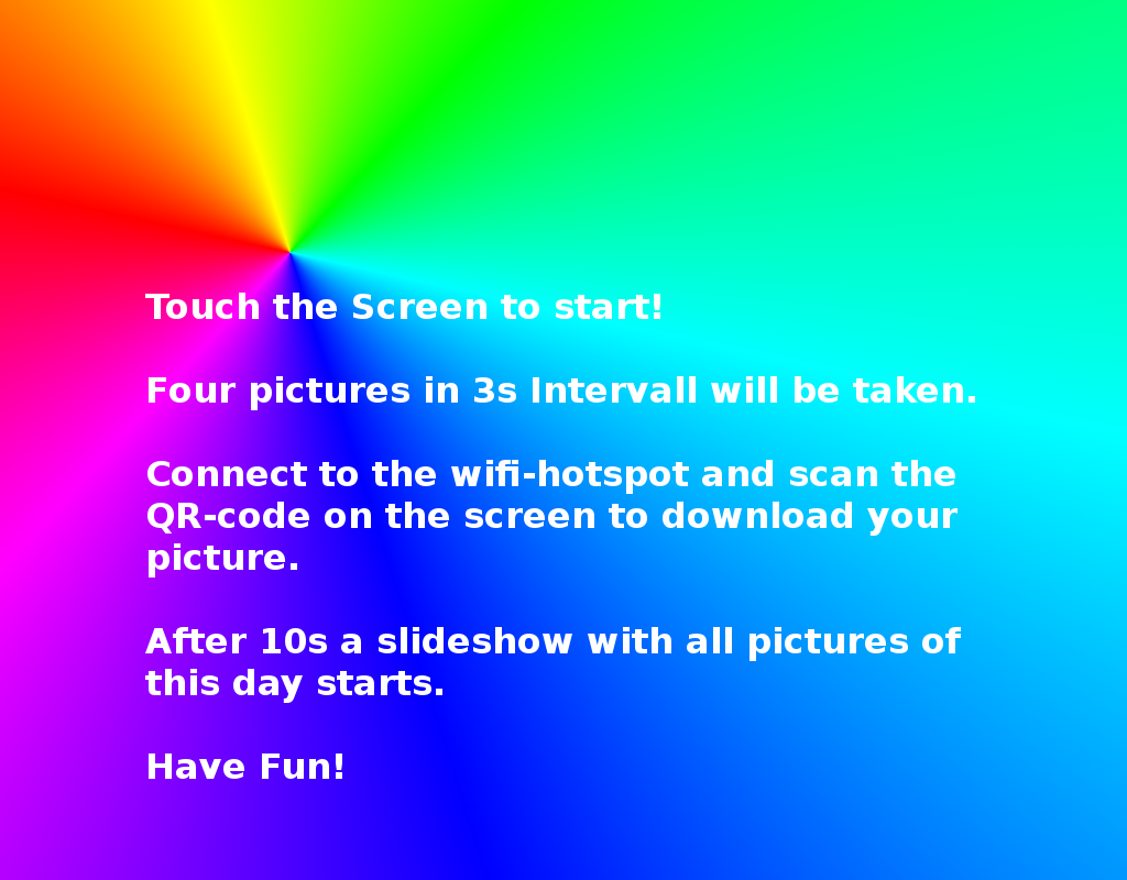
- the instructable-screen (startup)
- a startup-script which is called by crontab
The index.php.zip contains the website. This goes to /var/www/ and replaces the existing index.php which is there.
After you installed everything into /home/pi/pb just add
@reboot /home/pi/pb/startup.sh
to crontab and reboot you pi.
Then you should see the boot-screen and right after that the instructable-screen. If you have a different size of screen you might want to update this picture. I made it with gimp.
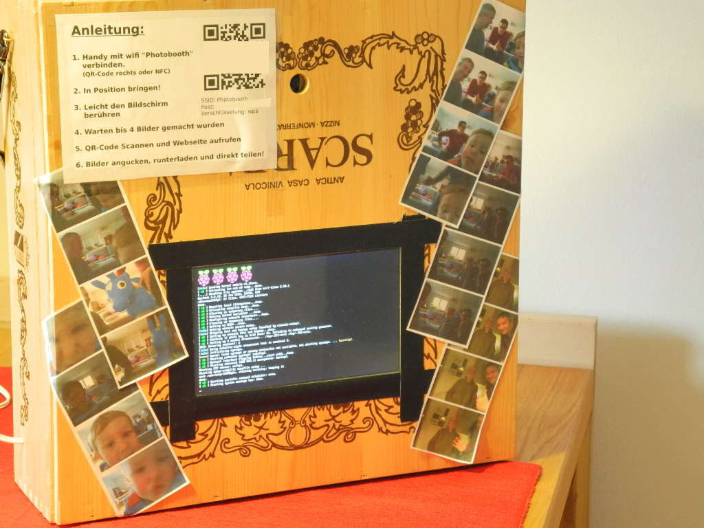
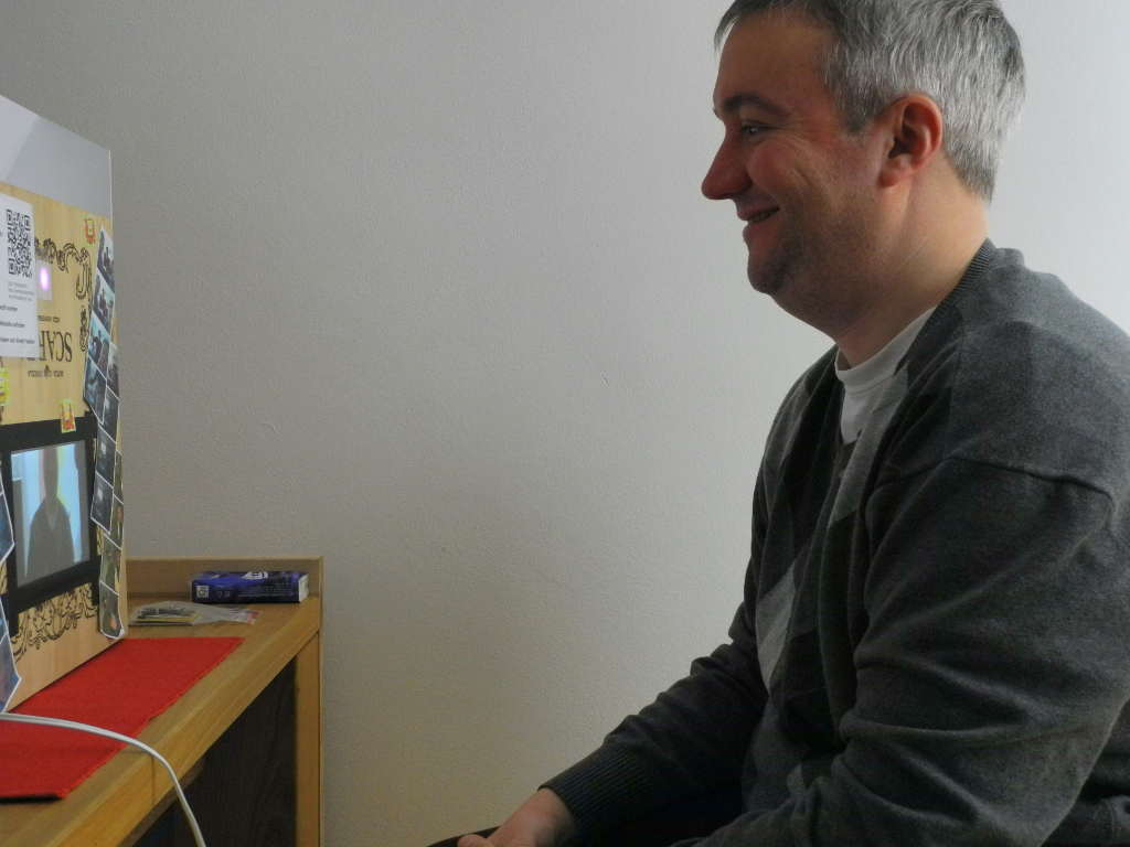
Setup and Use
You only need a power source and something to put the device on. I added an strap to hang it to a nail on the wall, but you can also place it on the table.
On the device itself I printed the instructions together with the info for the wifi-access point. And to make it really complete I also added an NFC-Tag beneath the description with the wifi-settings! There is no way to miss it!
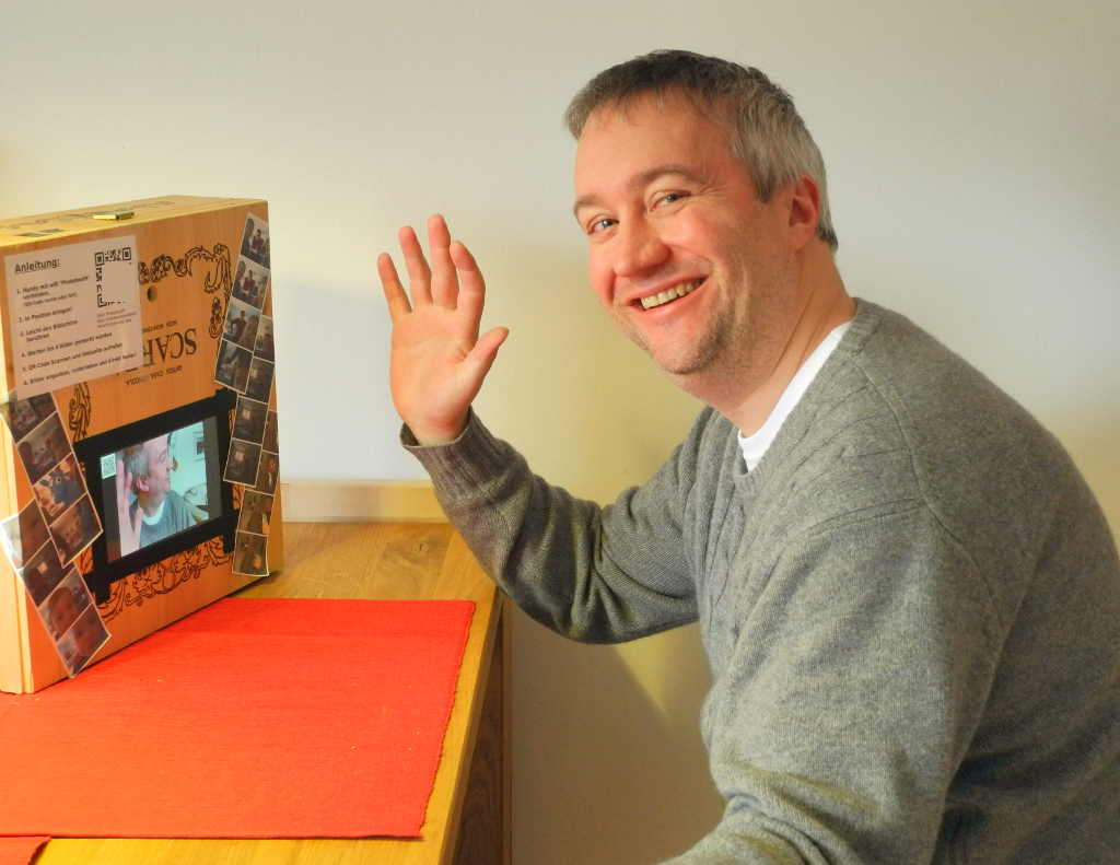
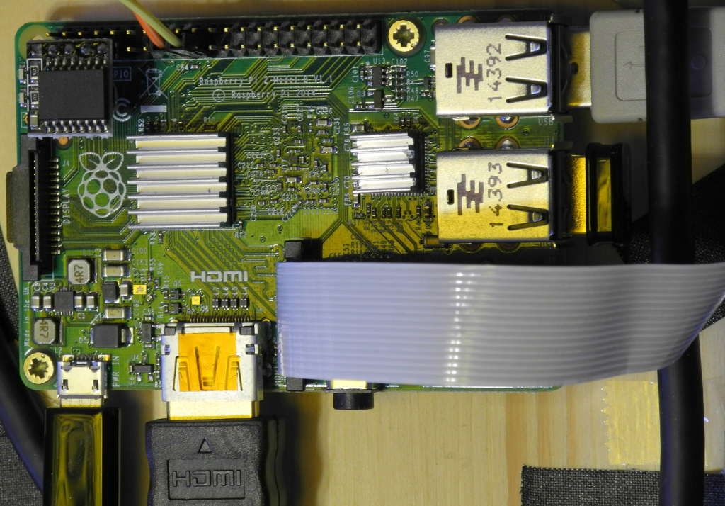
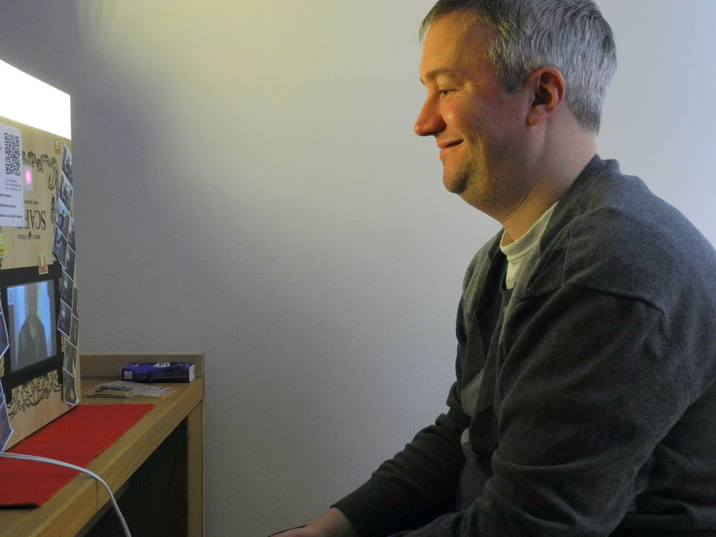
One thing I would make different the next time: The distance of the camera to the screen.
As you can see in the picture this is some 10cm. But as most of the people are looking straight to the screen, on the pictures it looks as if they looking slightly off. But I still might alter that one. You could even think about moving the cam-module itself to the outside instead of using a whole.
Add Artificial Light to the Photobooth

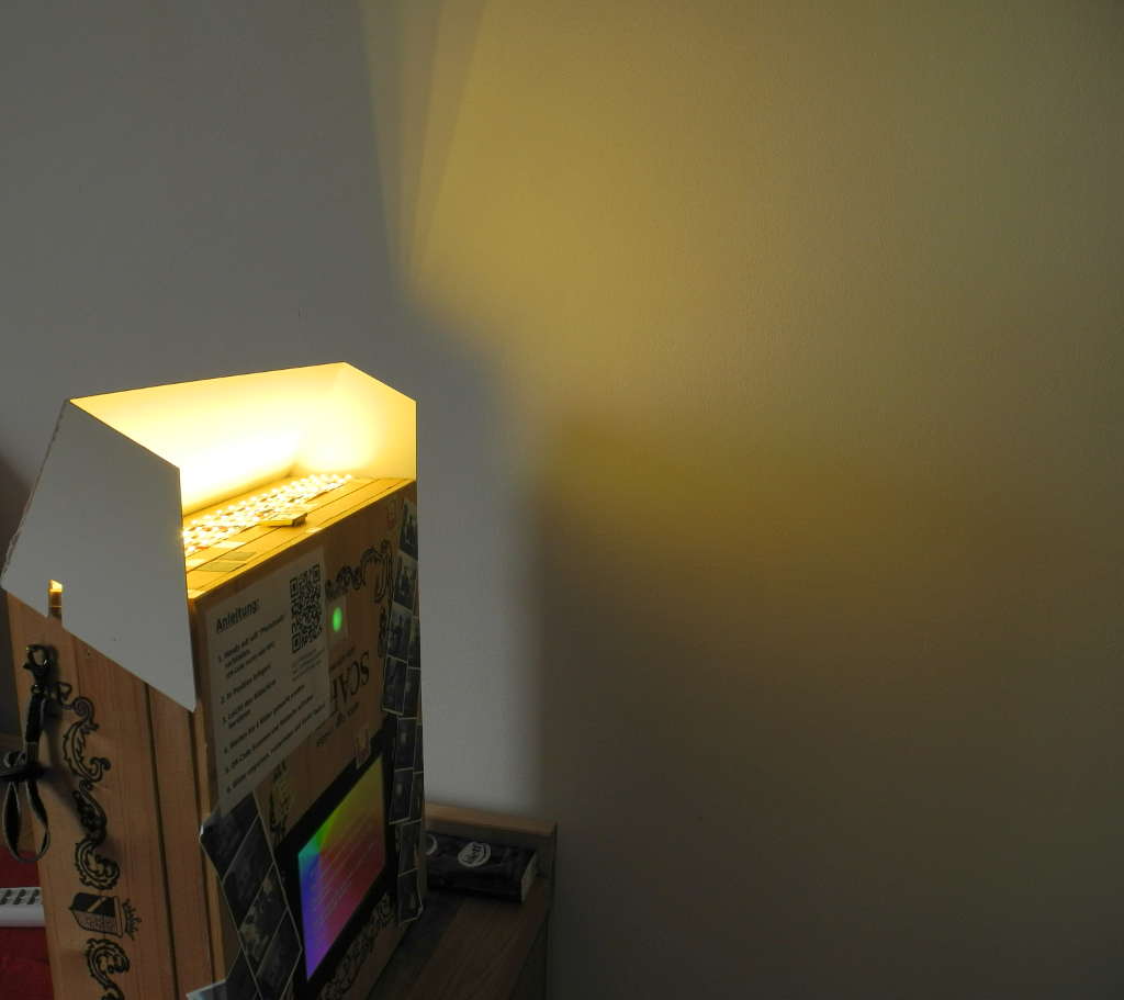
A few weeks ago I used the photobooth at a birthday party. The people had a lot of fun with it, but the camera looked into a rather bright room while the pictures and the faces were rather underexposed.
This is why I added an artificial light to the photobooth.
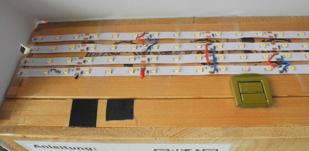
I added it to the top of the box and added a foldable white cardboard so nobody has to look straight into the LEDs. That would have been uncomfortable.
First step was to check how much current one strip needs. One strip with 21 LEDs needs 140mA at 12V. This is very handy, because I needed 12V for the touchscreen too. Altogether I used only 500mA at 12V before adding the light. This is why I could add four strips of 21 LEDs and still use my 2A-powersource.
And I didn't want to control the Light by the Raspberry, because that would have caused additional programming and how should the program know if the pictures are not well exposed? So I just added a switch inside the box and there we go!
Have fun and improve it further! I would like to hear what ideas you have!