Wifi Controlled Car Using MicroPython on ESP8266
by ASinMacc in Circuits > Microcontrollers
1508 Views, 9 Favorites, 0 Comments
Wifi Controlled Car Using MicroPython on ESP8266
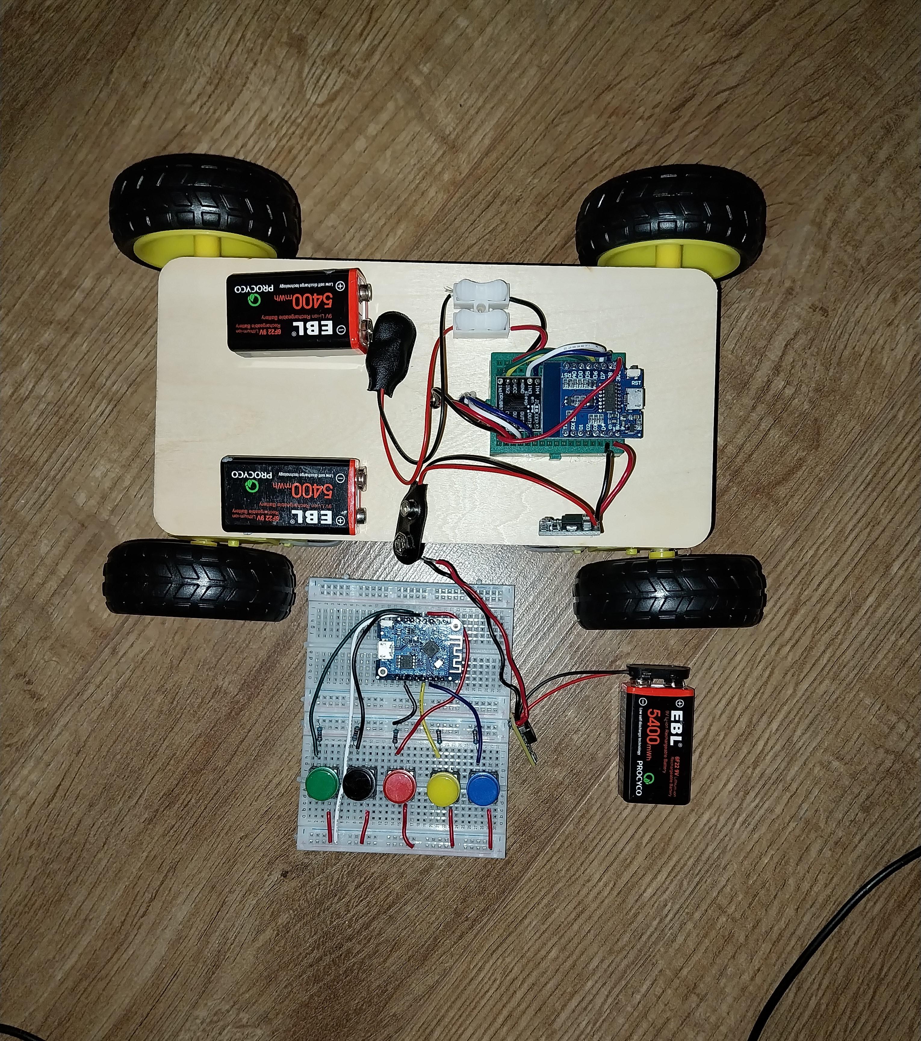
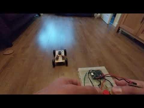
This project is to control a model car over WiFi using MicroPython running on a pair of ESP8266 microcontrollers.
The car is driven using an ESP8266 which creates a WiFi hotspot and a server to wait for commands. A separate ESP8266 is wired to a set of buttons - it connects to the car and sends commands to control it.
This is a project I created previously using C++ and the Arduino IDE - the key difference in this project is the use of MicroPython. It covers
- the PC installation of Python, ESP tools and Thonny IDE
- installation of micropython on the ESP8266 microcontrollers
- build of the WC (WiFi Controlled) Car
- build of the Controller
- The Python code on the car and the controller - including some "gotchas" in the use of micropython
The same project will work with ESP32 or Raspberry Pi Pico. I like the ESP8266 because they are so inexpensive and the small size of D1 Mini Node-MCU fits nicely onto a small breadboard - makes it perfect for the car.
Supplies
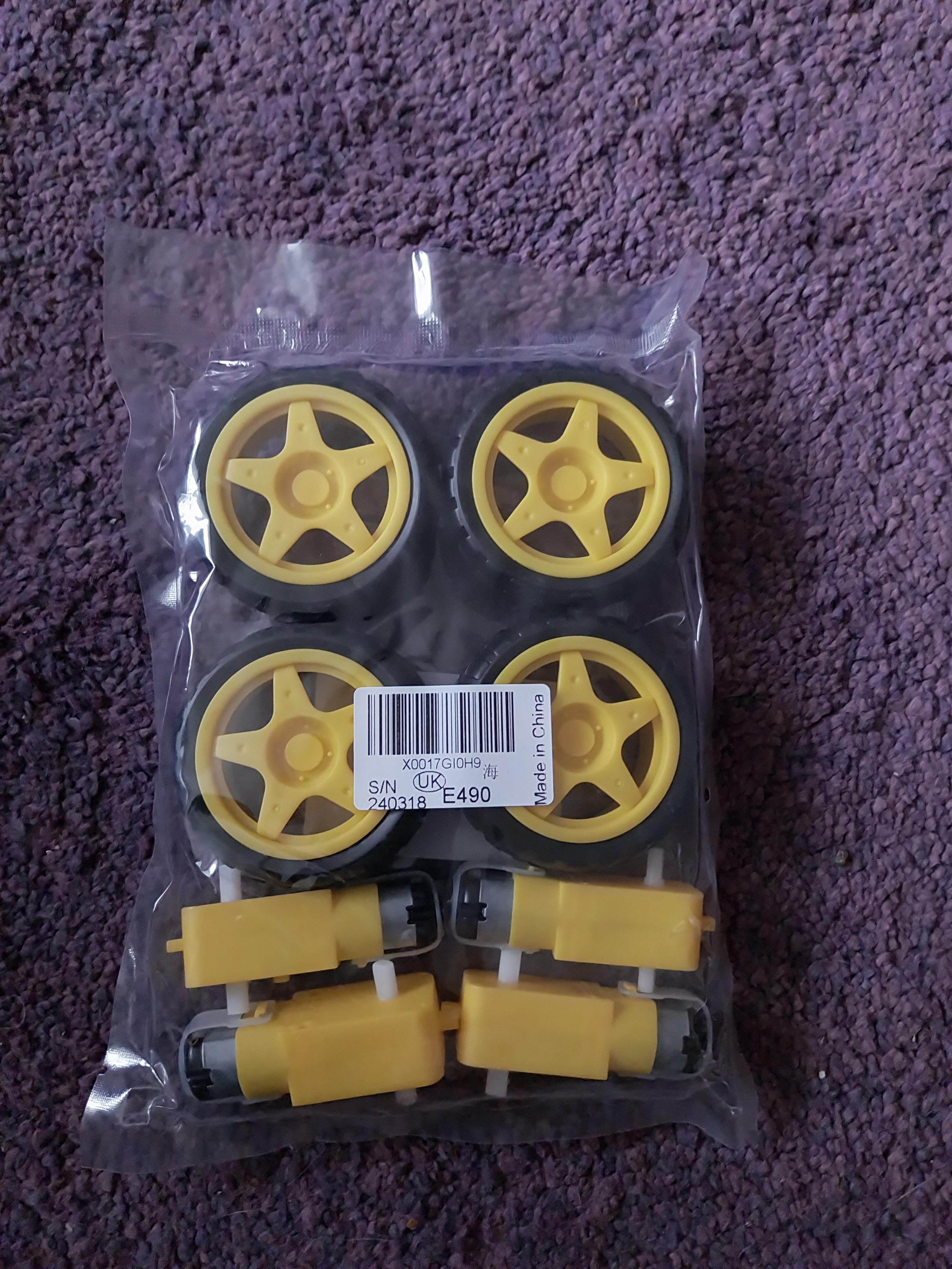
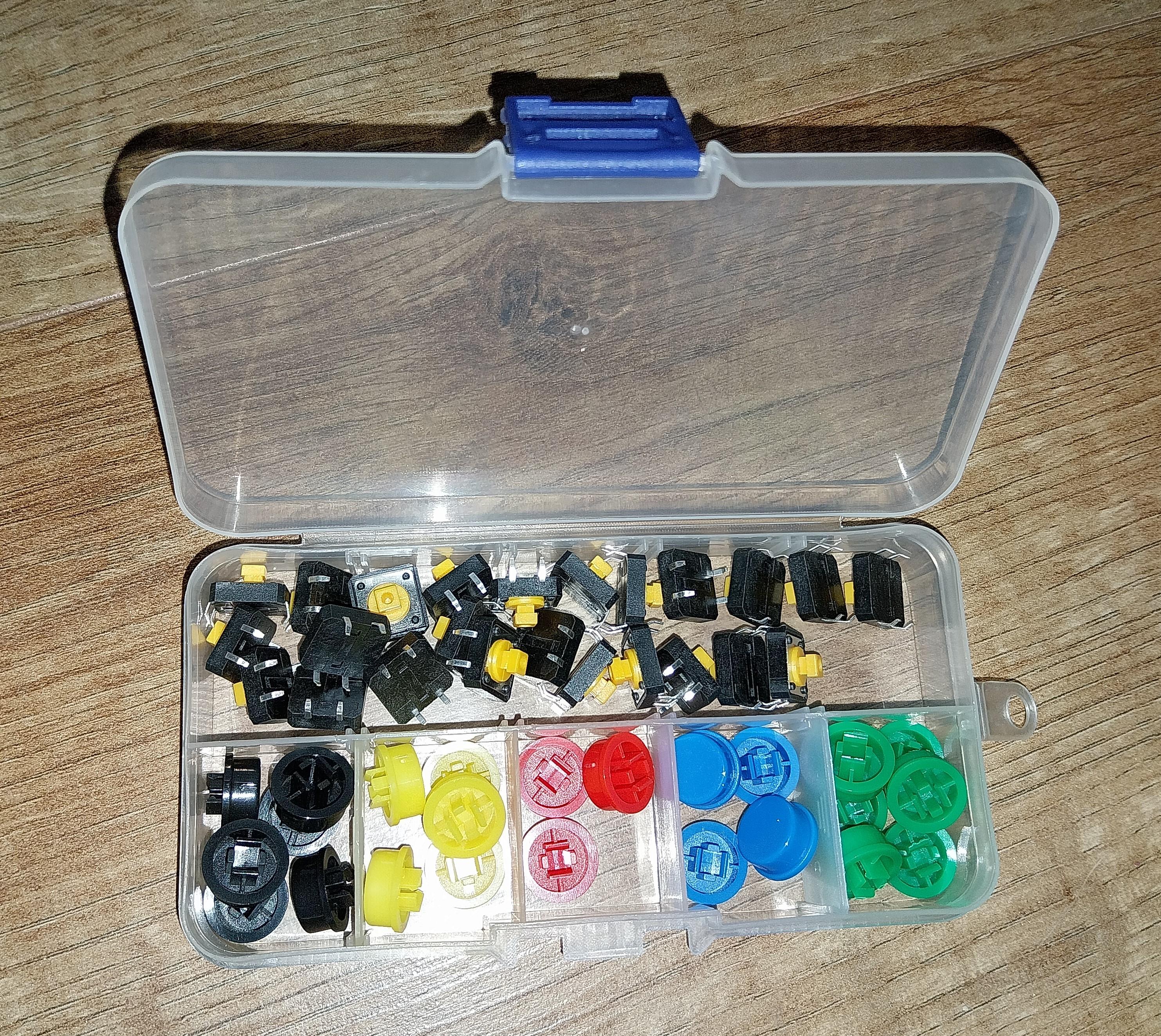
This can be done on a low budget, especially if you have some of these electronics lying around - biggest cost is the motors/wheels. I have put some approximate UK costs in brackets below - the items are all readily available from eBay, Amazon or BangGood but prices vary a lot - shop around..
CAR
- ESP8266 – Mini Node-MCU. The smaller device allows it to be fit on a small breadboard. The cheaper ones come without header pins attached - so you will need to get the soldering iron out. It is possible to pay a little more for pins already soldered - but where's the fun in that? (£3 - can get 5 for less than £15 from Amazon)
- DRV8833 Motor Driver. The L298N driver also works but DRV8833 is smaller and fits onto the breadboard with the Mini NodeMCU. Again, for the cheaper ones, you will need to solder header pins. (£1 - can get 5 for £5)
- Small Breadboard for the electronics in the car (less that £1)
- 4 x Geared Motor with plastic wheels (£8 for 4 motors with wheels)
- Small wooden board as the car chassis (less that £1)
CONTROLLER
- ESP8266 – Mini Node-MCU. (£3)
- Coloured buttons to be mounted on breadboard (can get a big box of coloured button for £5)
- Two Medium breadboards (or one large) for the Controller (£3)
- 5 x Resistors 10K (less that £1)
POWER
- 3 x 9V batteries (£2)
- 2 x Voltage Regulator – to provide a 5V power to the ESP8266 (£2 - can get 10 for £10)
- Battery connectors (£1)
TOOLS & EXTRAS
- Wires
- Hot Glue Gun
- You will need a Windows PC - athough this can all be done with Linux PC
- Multimeter - always useful
- Soldering iron
PC Install
We want Micropython on the MicroController but to get there, we need Python on a PC . The steps are:
- Install Python on the PC
- Install the tools to interact with the ESP8266
- Install Thonny – this is the IDE (the development environment used to manage code)
Download Python from https://www.python.org/downloads/ - the installation is straightforward but couple of things to watch for.
- select a custom install
- install in an explicit path of your choice (override the default ..win/AppData/Local)
- install for all users
- add python to the Path - this means we can run commands from the command line
There are some Python tools that we use to access the microcontroller using Python.
- Open a command prompt
- Check that the Python install worked. Enter command:
- python -V
- We’ll be using the Python package installer pip. Enter command:
- pip-V
- That shows that Python is installed correctly – we can now install our Python tools. Enter command:
- pip install rshell esptool
Now we need Thonny. Thonny is a great IDE that works really well with microcontrollers – we’ll see how later.
You can install Thonny from https://thonny.org/ - which then uses its own version of python -removing the need for the separate Python install. But I prefer explicit control over Python, so install Thonny into my Python install.
- Enter command:
- pip install thonny
We'll be using Thonny later
Install Micro Python on ESP8266
To install the micropython, we need to replace the firmware on the microcontroller.
- Download the latest micropython firmware from here: https://micropython.org/download/ESP8266_GENERIC/
- Connect the ESP8266 to the PC using a USB cable (make sure it is not a power-only cable)
- Open a command prompt and go to the folder containing downloaded firmware. Enter command:
- rshell -l
- “USB Serial Device 10c4:ea60 with vendor 'Silicon Labs' serial '0001' found @COM3”
- This shows the port that our microcontroller is connected to. Usually COM3, COM4, COM5 etc.Whatever value is shown, use that in the commands below
- Backup the existing firmware – this would allows us to revert back to previous setup if we choose later. Enter command:
- esptool --port COM3 -b 460800 read_flash 0x00000 0x400000 flash_Before.img
- Now we delete the existing firmware
- esptool --port COM3 erase_flash
- And now we install micropython – use the filename of the file we downloaded
- esptool --port COM3 --baud 460800 write_flash --flash_size=detect -fm dio 0 ESP8266_GENERIC-20240602-v1.23.0.bin
- Can perform a quick check that python is working - Enter command:
- rshell --port COM3
- This opens a remote shell, then Enter command:
- repl
- We are now in a micropython interpreter
- print("Hello world")
- exit back to command line with Control-X and then Control-Z
Repeat the same for the other microcontroller.
Car Build
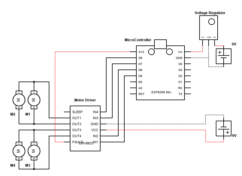
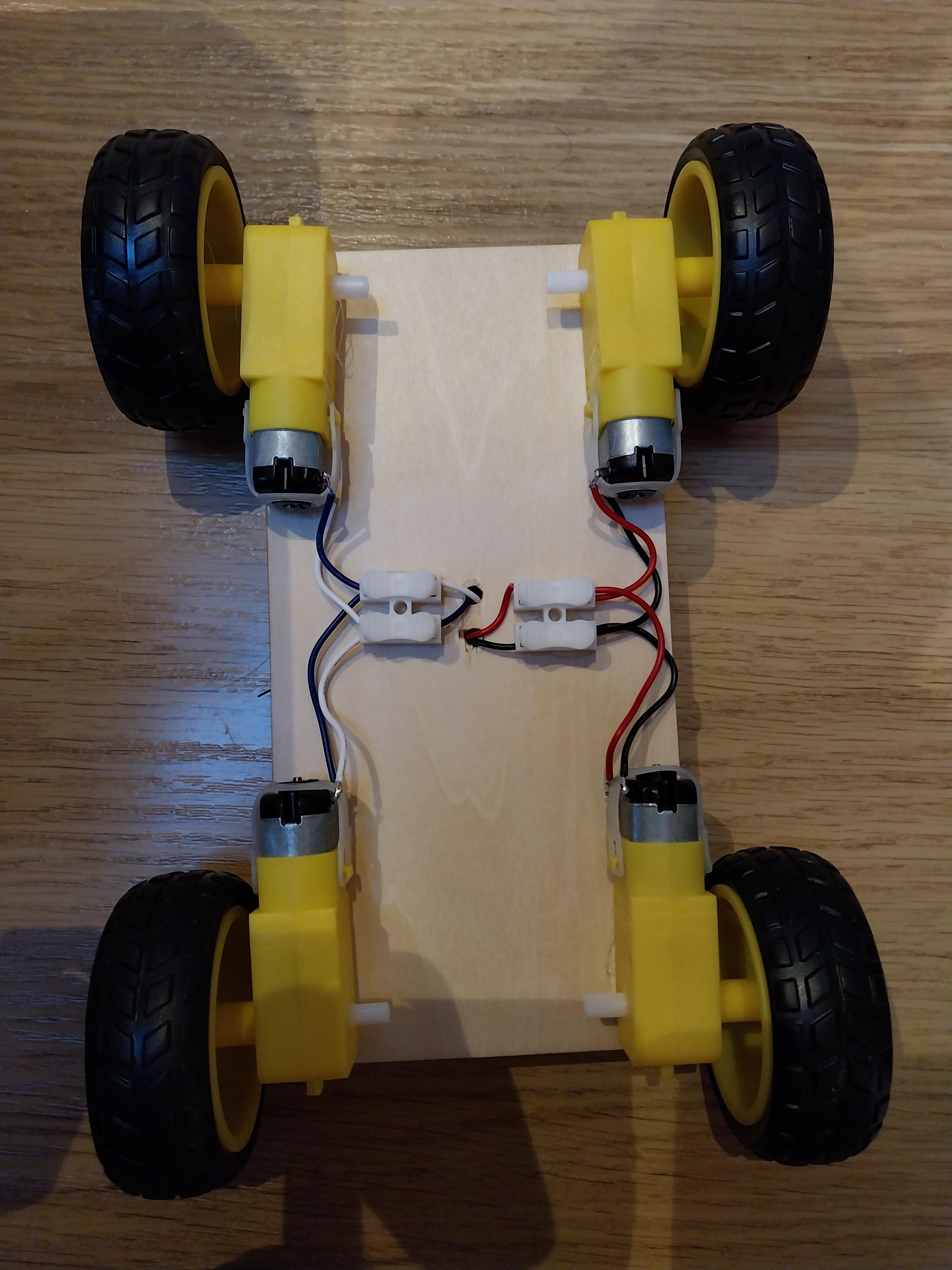
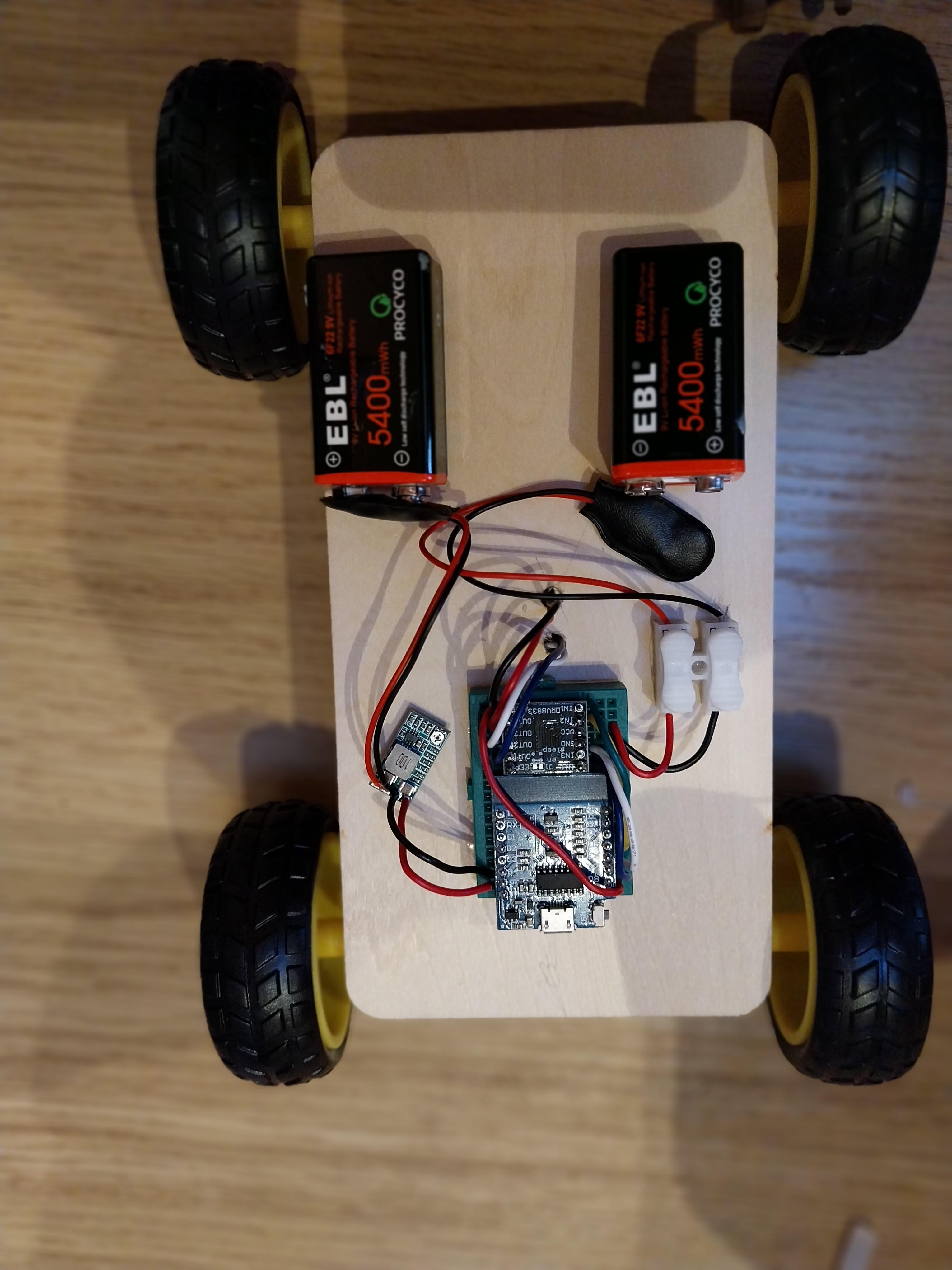
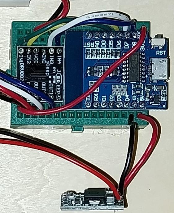
I have built multiple variants of this - including a tank chassis and a "build yourself" model car chassis. The easiest and most fun is to just use the 4 motors and a light piece of wood as a chassis.
- Use a piece of wood as a chassis - drill a hole in the centre which will take the wires from the motors
- Alternatively use Lego plate as the chassis
- Using hot glue, affix the 4 motors to the underside of the chassis and feed the wires from the motors through the hole in the chassis
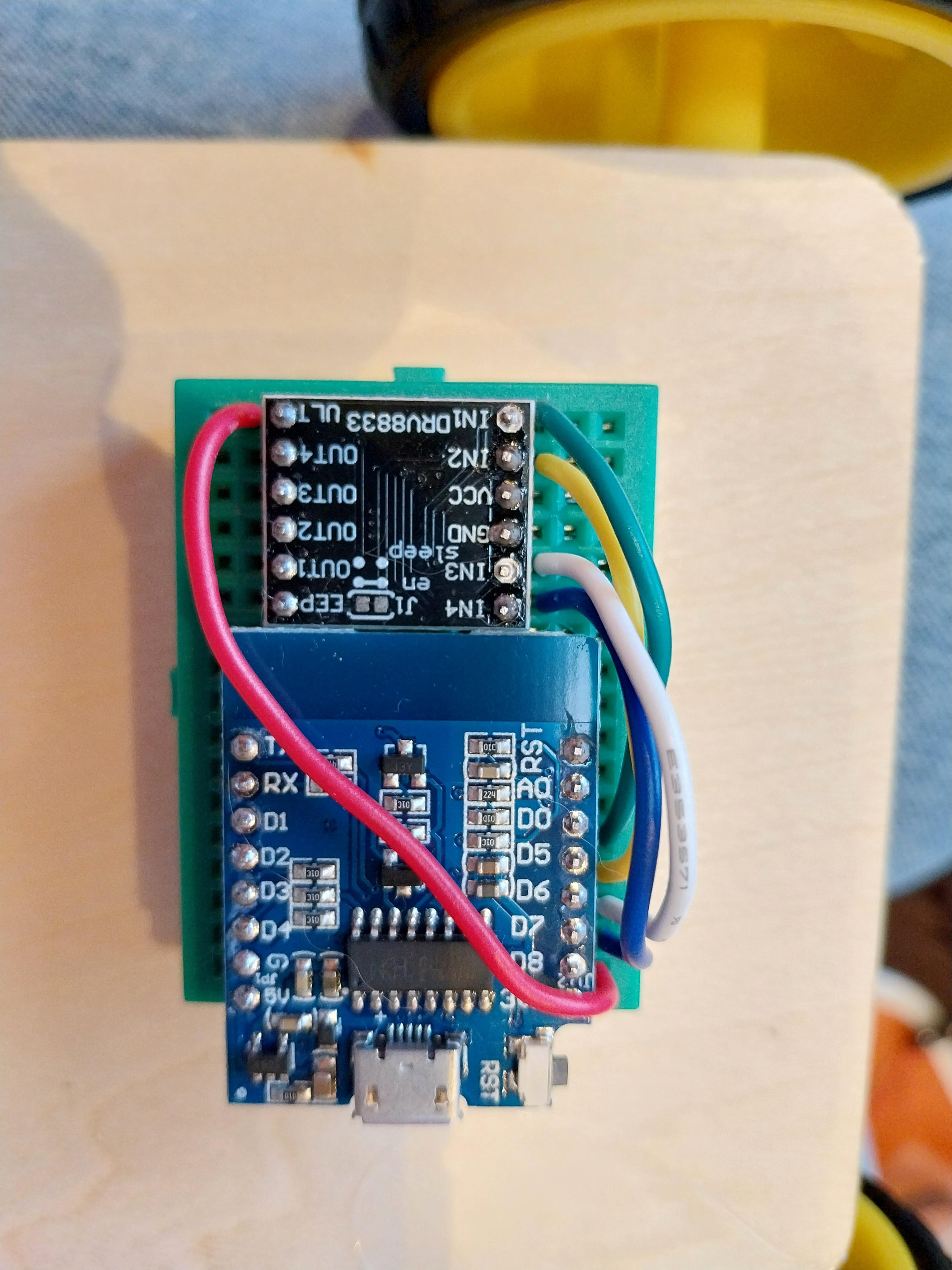
- Use a small breadboard - plug in a microcontroller and a DRV8833 motor driver
- this is a key reason to use a Mini NodeMCU - it is compact enough to fit on the small breadboard with the motor driver
- Connect the wires from the motors to the motor driver - one motor to Out1 and Out2, the other motor to Out3 and Out4.
- Connect the microcontroller to the motor driver
- D5 to In1, D6 to In2
- D7 to in3, D8 to In4
- 3v3 to "Fault"
- The car needs 2 batteries to be connected
- One battery needs the 5V regulated voltage connected to the microcontrollers 5V and GND.(see step 5)
- Note that this connection is not needed when the controller is connected to the PC over USB
- The other battery (unregulated) can connect to the VCC and GND of the Motor Driver
- For both connections, we need to make sure that the + and - are the right way around
Controller Build
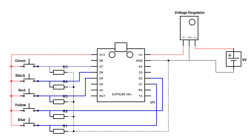
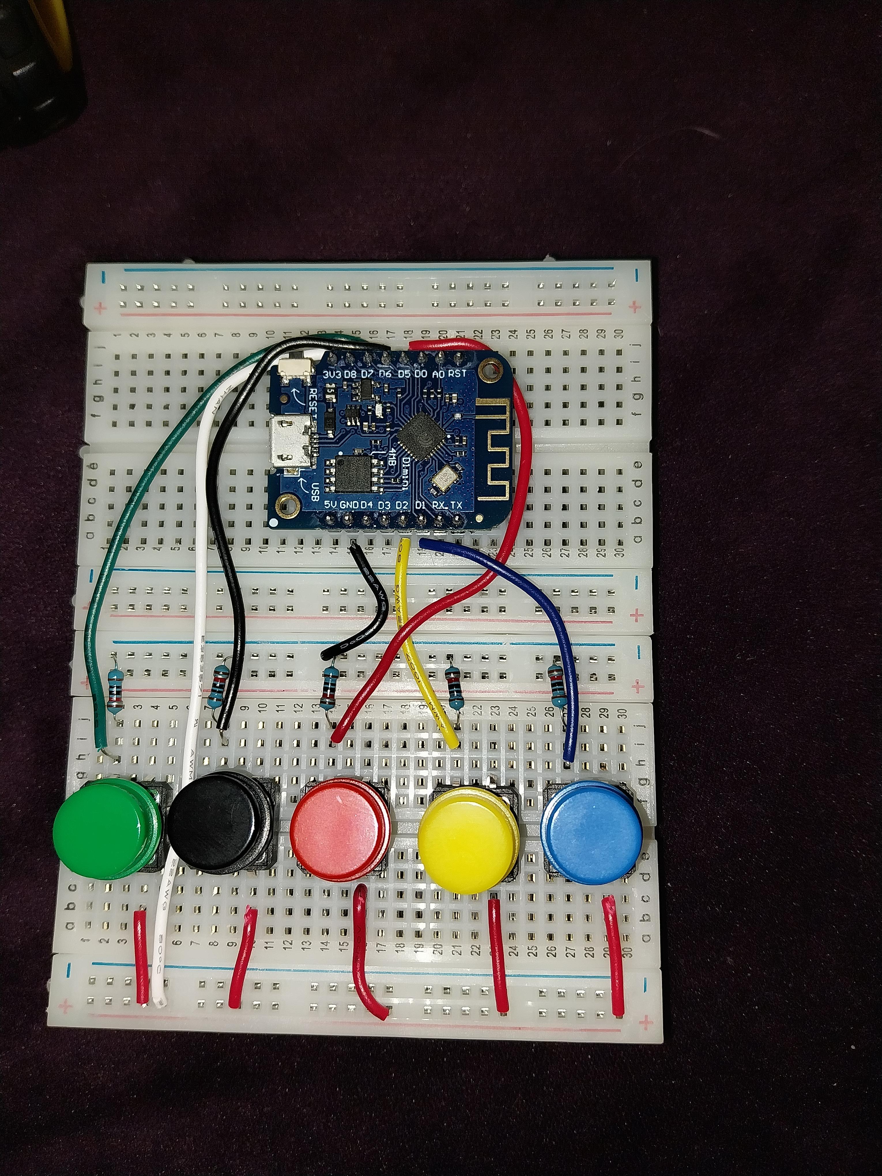
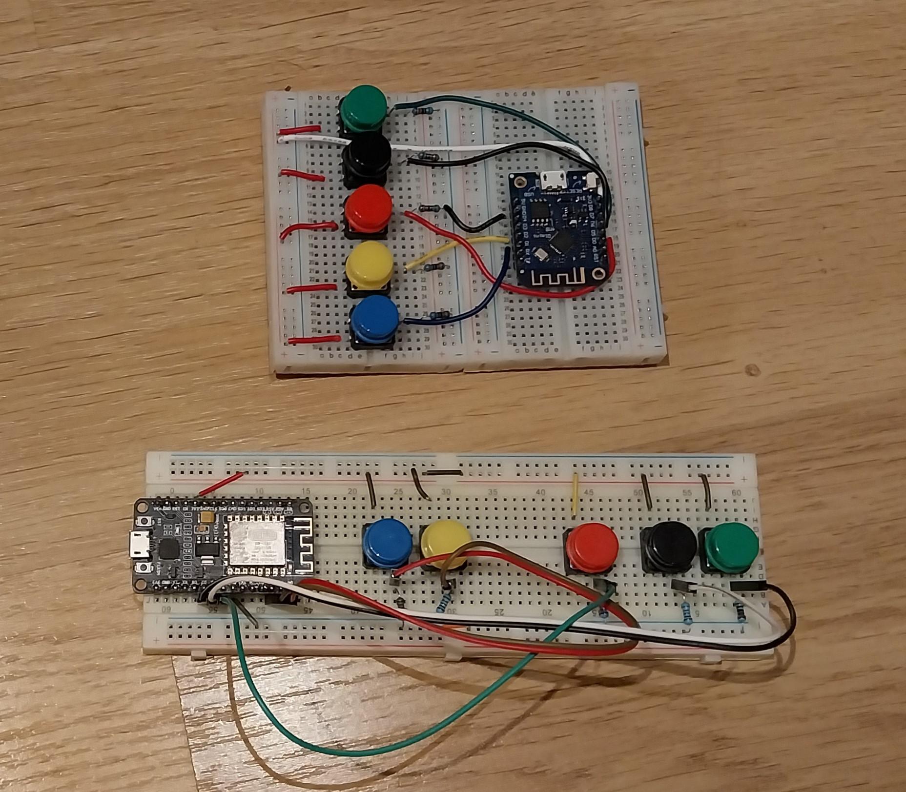
I built the controller with 5 buttons - each a different colour. I used different colours to help explain the code logic. Each button is wired with one side directly to the positive rail, the other side to the negative rail through a 10K resistor and then a connector from the button to a pin on the microcontroller:
- Green to D7 - this drives Left motor Forward
- Black to D6 - this drives Left motor Backward
- Red to D5 - this is not currently used - for a future idea
- Yellow to D2 - this drives Right motor Backward
- Blue to D1 - this drives Right motor Forward
Additionally, we need power to the Microcontroller
- A battery with 5V regulated voltage must be connected to the microcontrollers 5V and GND (see step 5)
- Note that this connection is not needed when the controller is connected to the PC over USB
Battery Power
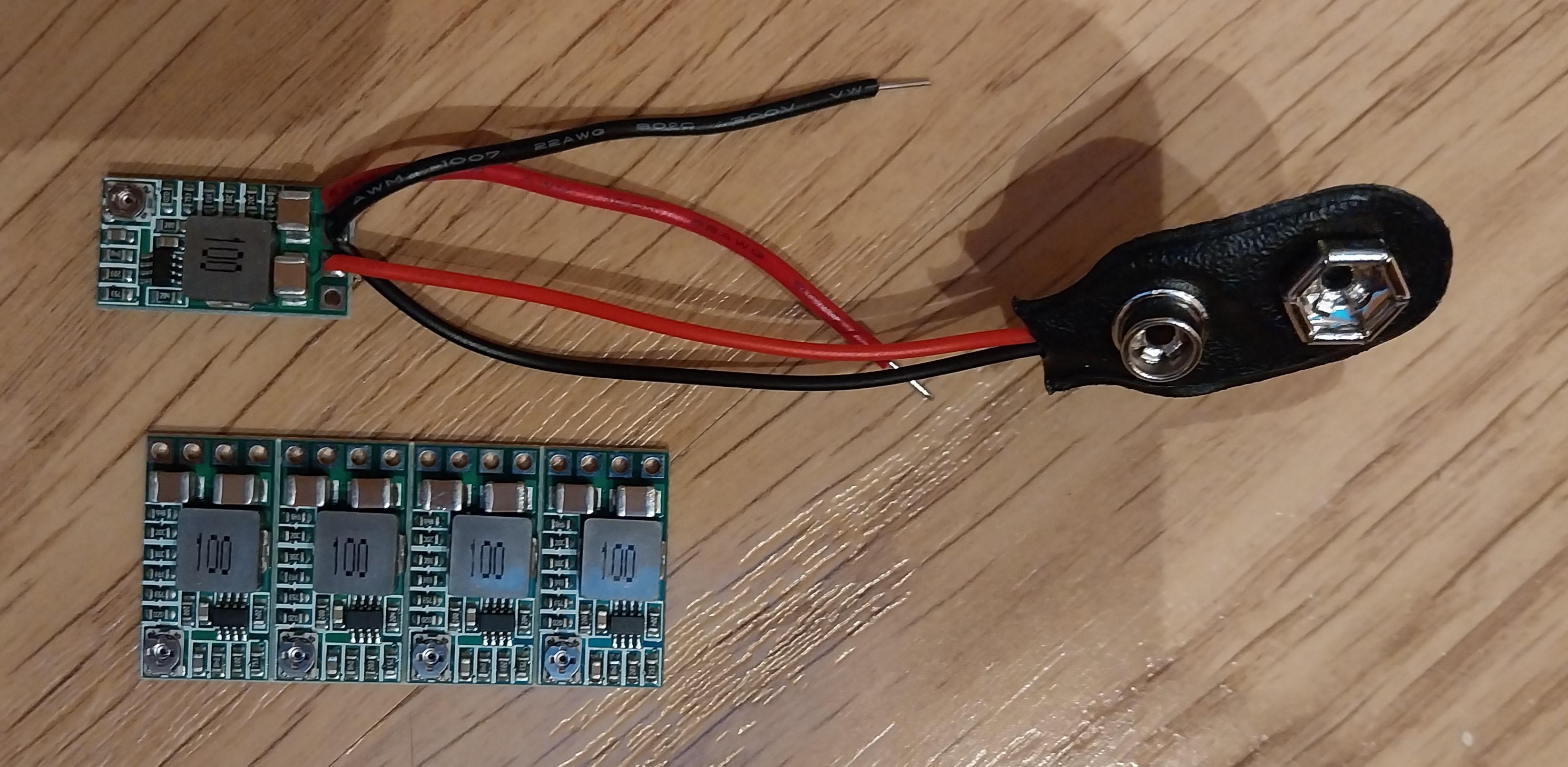
The car needs 2 sources of power - one to power the ESP8266, the other to power the motors. It is possible to use the same battery for both, but I found that the power to the MicroController was not stable enough and caused it to restart regularly. The controller just needs power to the ESP8266.
My preference is to use 9v batteries - I use rechargeable but cheap "pound shop" batteries do the job.
The battery for the motors can just go direct to the Motor Driver - it's slightly too high a voltage but these motors seem pretty resilient. If worried, the use a voltage regulator like below.
The power to the ESP8266 does need to be 5V to the 5V and GND pins. There are multiple ways to get 5V - I like these little Step Down Power Supply modules. They come in a strip of 10 for less that £10. You will need to solder some wires onto it. A battery connector from the IN+ and GND. Then 2 wires to the VO+ and GND.
These are adjustable for the voltage they output.
- either connect the output to a multimeter and just using the small screw until you get near to 5V
- or it is possible to put a small piece of solder on the back to fix it at 5V
When the ESP8266 is connected to a PC over USB (next steps) there is no need to connect a battery.
For all of the wiring, I have a box of use single core 22AWG wire. It is easy to solder, it plugs directly into breadboard and is easy to cut to length.
Python Code - Car
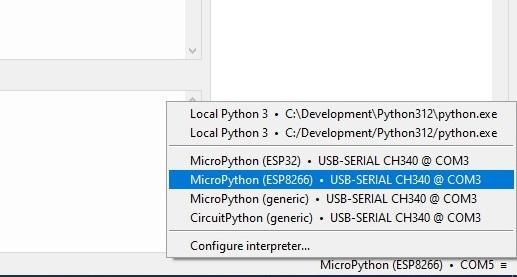
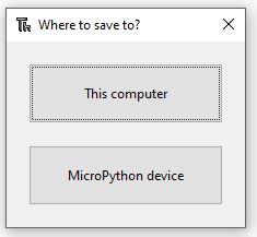
Download the python code files to a local folder, we then need to move the code to the the ESP8266 on the car. Multiple ways to do this but the easiest is to open the file in Thonny and "Save As" to the MicroController.
- Connect the ESP8266 to the computer with a USB cable
- From a command prompt, Enter command rshell -l to just check that it is connected ok
- Open Thonny - as installed in Step 1
- At the bottom right corner of Thonny, should be able to select ESP8266 on the COM Port
- Before loading the car's software, we'll test the motors...
- From local disk, Open the python code MotorTest.py
- SaveAs and select "MicroPython Device" - save with the same name
- With the car lifted off the ground, press Run
- This will move the motors in sequence
- Both motors forward / Both motors Backward
- Left forward / Left backward
- Right forward / Right backward
- Spin Left / Spin Right
- If the motors do not spin as expected, check the connections
- If a motor spins in the wrong direction, may need to reverse the connections on the motor
Once the motor test passes, we can now load the software
- For each of the files WCCar.py WFServer.py boot.py
- Open in Thonny
- Save As to the Micropython Device
How does the code work ?
- The file WCCar.py is the main program to run
- Initialisation will setup the 4 pins to send output to the motor driver
- As part of initialisation it will turn the wheels briefly to show that it is working
- It creates a WiFi hotspot using the settings at the top of the program
- WIFI_SSID = "WiFiCar1"
- WIFI_PWD = "WiFiCar1"
- If you create multiple cars - each one will need a different SSID
- You may change the SSID and password - but a really important point - once the code has been run and an SSID set, the SSID cannot be changed, it will always try to use the same SSID. If you really need to change it, you'll need to erase the firmware and reinstall micropython
- Once the hotspot is created, it creates a server to listen for commands
- It expects 3 letter commands
- The first letter is the control for the left motors : F for Forward or B for Backwards or S for Stop
- The second letter is the control for the right motors : F for Forward or B for Backwards or S for Stop
- The third letter is not used - it is intended for future use (as a weapon)
- There is error checking - if we get no new commands for a period, it will close and re-initialise connections. This will result in the Controller losing its connection
Python Code - Controller
Download the python code files to a local folder, we then need to move the code to the the ESP8266 on the car. Multiple ways to do this but the easiest is to open the file in Thonny and "Save As " to the MicroController.
- Connect the controller ESP8266 to the computer with a USB cable
- From a command prompt, Enter command rshell -l to just check that it is connected ok
- Open Thonny - as installed in Step 1
- At the bottom right corner of Thonny, should be able to select ESP8266 on the COM Port
- Before loading the Controller’s software, we'll test the buttons...
- From local disk, Open the python code ButtonTest.py and Button.py
- SaveAs and select "MicroPython Device" - save with the same name
- For ButtonTest.py, press Run
- Can now press each of the buttons – including multiple at a time
- The Output in Thonny will say which buttons are pressed
- Check each of the buttons
- If a button does not register, check the connections
Once the motor test passes, we can now load the software
- For each of the files Controller.py WFConnect.py boot.py
- Open in Thonny
- Save As to the Micropython Device
How does the code Work ?
- Initialisation first will setup the pins for input
- The Controller will connect to the hotspot of the car and attempt to connect to the server
- The SSID and password in the code must match those used on the Car (WCCar.py)
- In a loop, the code will assess what buttons are being pressed (if any)
- If there is a change to which buttons are pressed
- Work out from the buttons whether we want to move the left or right motors Forward / Backward / Stop
- Build a 3 letter command and send to the Car
- The code includes error checking in case the connection has been dropped, it will reconnect to re-establish a connection
Next Steps & Other Options
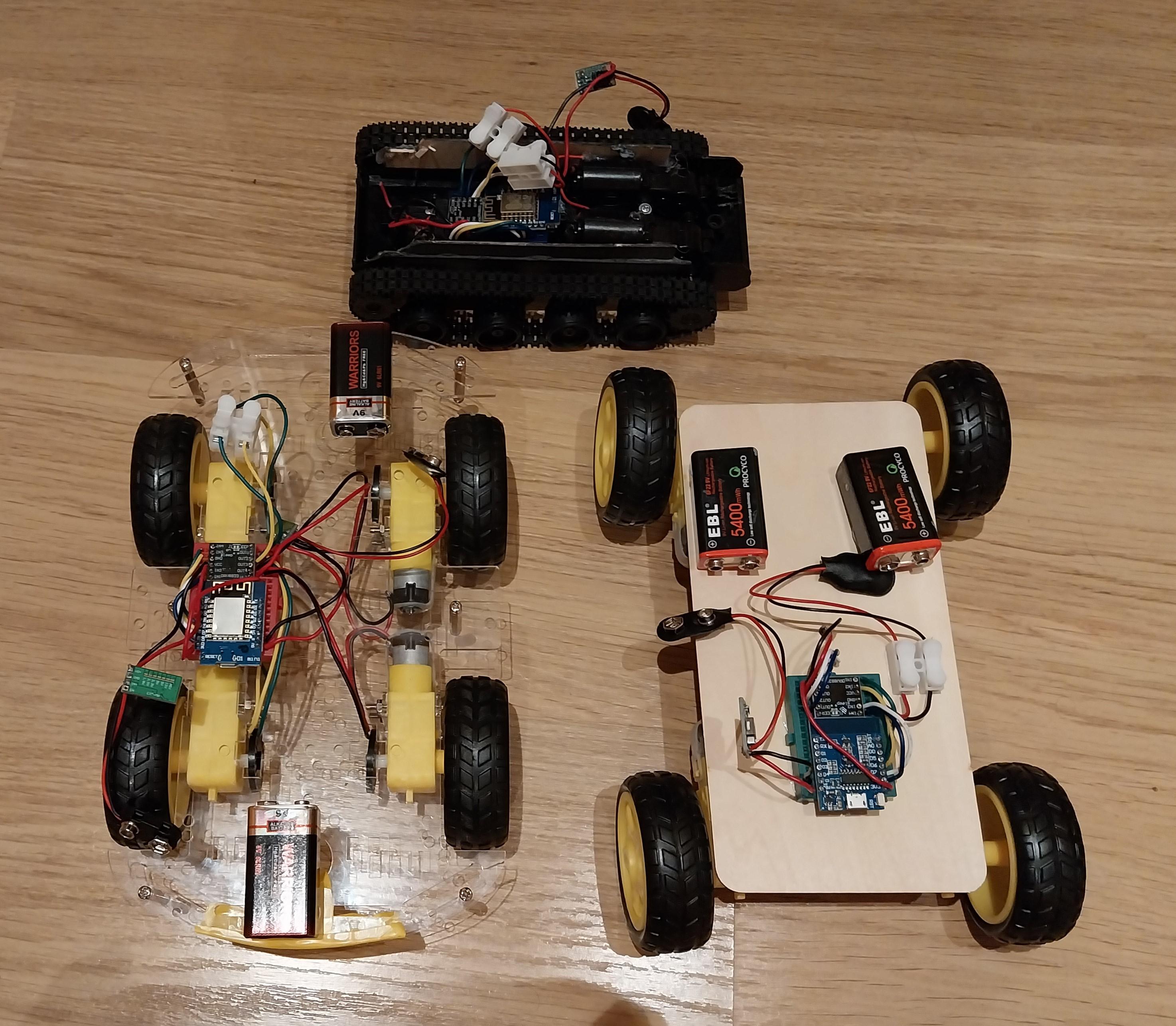
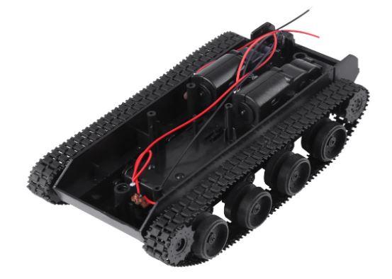
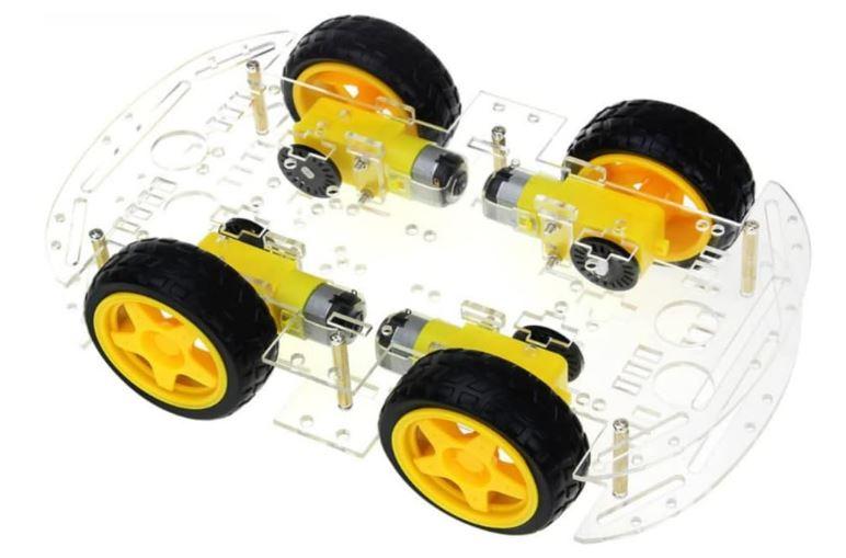
Gluing motors to a piece of wood does not look great, you can buy something a little neater. Including
- A tank chassis with 2 motors, tank tracks and battery compartment underneath. The wiring and the code is the same as described above
- A "screw together" car chassis with 4 motors. There is a 2 motor and 4 motor variant (use the 4 motor) - but wiring and code is the same
Next Steps for advancement
- Get a PCB instead of using a breadboard - avoids issues with wires coming loose
- Build a body/roof for the car
- Use the extra button... Ideas including wiring a laser to use as a "weapon" to hit light sensors
- Alternate control mechanism making it easier to control.
- The code needs tidying up - needs to go on GitHub