When IoT Meets AI: Home Automation With Alexa and NodeMCU
by mjrovai in Circuits > Wireless
22847 Views, 144 Favorites, 0 Comments
When IoT Meets AI: Home Automation With Alexa and NodeMCU
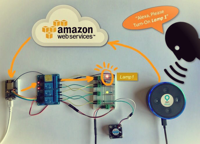
What we will explore on this tutorial, is how to use Alexa, an intelligent personal assistant developed by Amazon Lab126, made popular by the Amazon Echo and Echo-Dot.
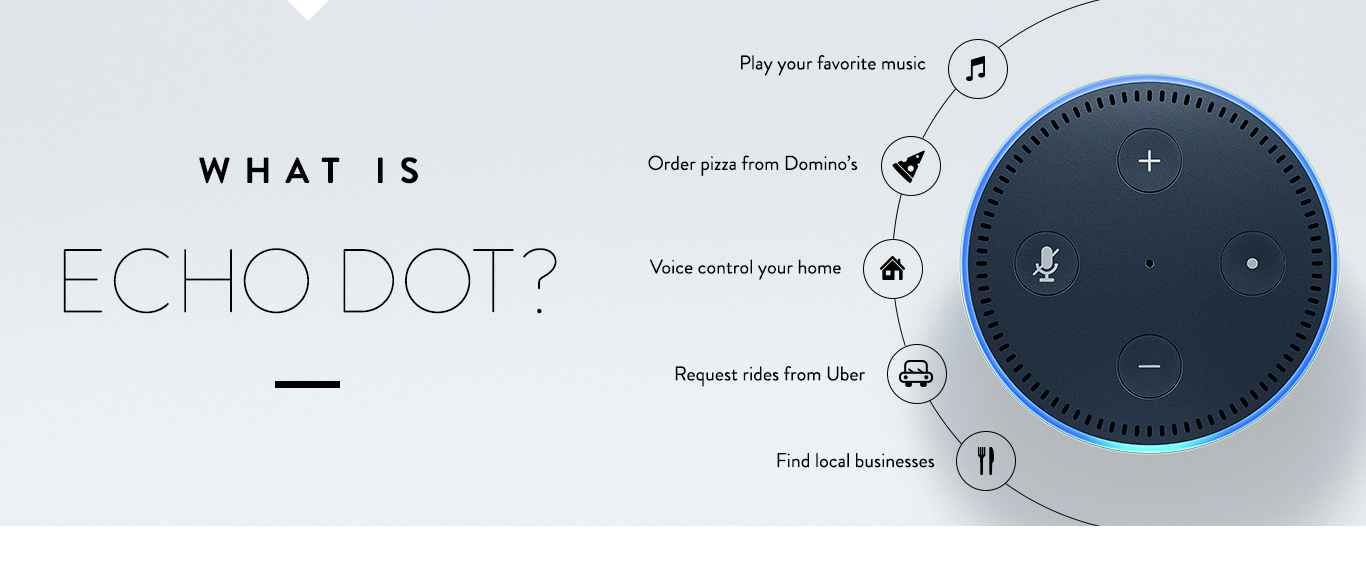
Alexa is capable of voice interaction, music playback, making to-do lists, setting alarms, streaming podcasts, playing audiobooks, and providing weather, traffic, and other real time information. Alexa can also control several smart devices using itself as a home automation hub. We will use on this project, the "Echo-Dot", that allows users to activate the device using a wake-word (such as "Alexa").
In the home automation space, Alexa can interact with several different devices as Philips Hue, Belkin Wemo, SmartThings, etc. In our case, we will emulate the WeMo.
WeMo is a series of products from Belkin International, Inc. that enables users to control home electronics from anywhere. The product suite includes a switch, motion sensor, Insight Switch, light switch, camera and app. The WeMo Switch (our case here) can be plugged into any home outlet, which can then be controlled from an iOS or Android smartphone running the WeMo App, via home WiFi or mobile phone network.
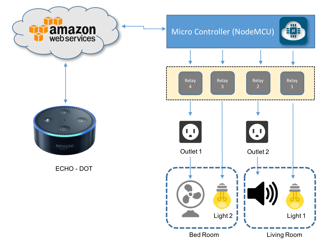
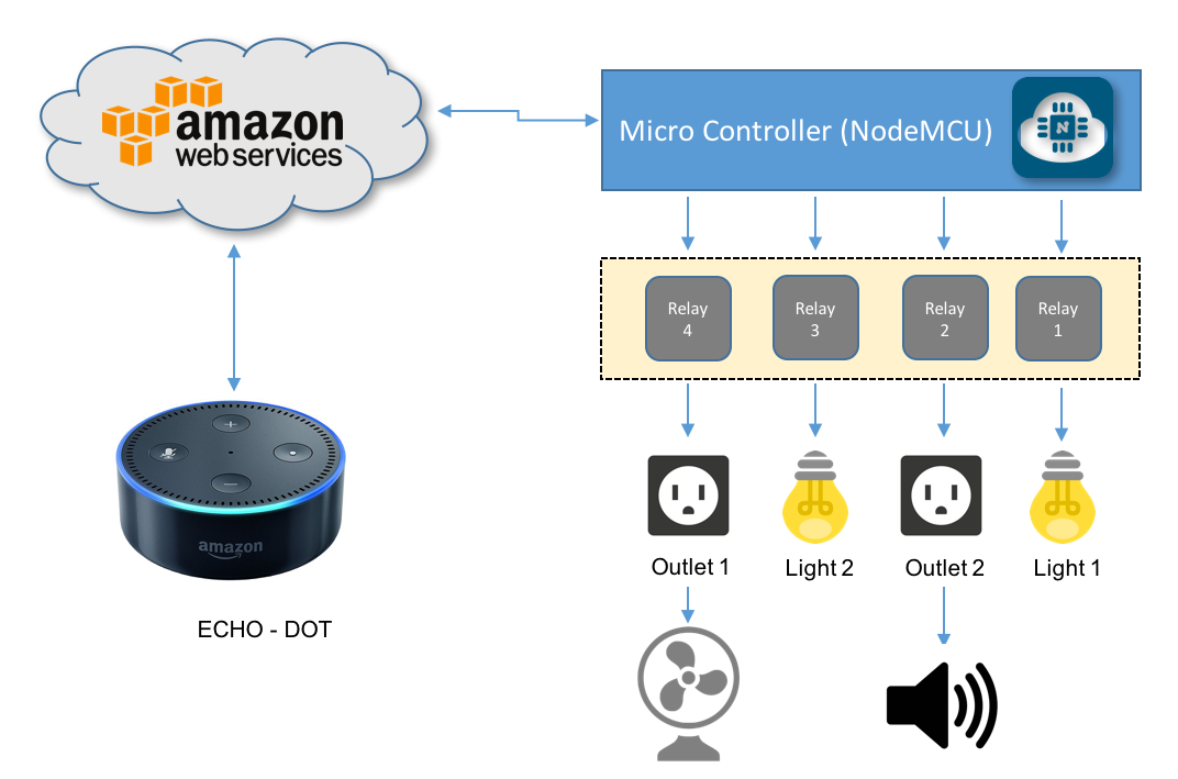
The above block diagram shows what will be developed on our project.
The below video, shows how the project will look like at end:
Bill of Material (BoM)
(All values are referencial in USD)
- NodeMCU ESP8266-12E ($8.79)
- Echo Dot (2nd Generation) - Black ($49.99)
- Mini BreadBoard ($1.00)
- 400-point Experiment Breadboard Breadboard ($ 4.97)
- 4-Channel Relay Module ($8.49)
- LEDs (Red and Green) ($1.00)
- 2 x Resistor (220 ohm)
- 5V 2 Terminals Electronic Continuous Sound Buzzer ($1.00)
- Male-Female Dupont Cables ($1.00)
- DC 5V 0.2A Cooling Fan ($4.00)
- External 5V power Supply or battery
WeMo Emulation
In the article: HOW TO MAKE AMAZON ECHO CONTROL FAKE WEMO DEVICES, wrote by Rick Osgut you can learn the bases of WeMo emulation.
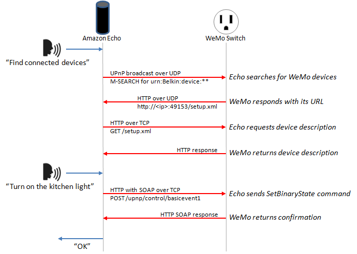
The WeMo devices use UPnP to perform certain functions over the network. The device detection function starts out with the Echo or Dot (in our case here, the Dot) searching for WeMo devices using UPnP. The device then responds to the Dot with the device’s URL using HTTP over UDP. The Dot then requests the device’s description using that HTTP URL. The description is then returned as an HTTP response.
The actual “on/off” functionality of the WeMo devices is simpler since the Dot already knows about the device. The Dot simply connects to the WeMo over the HTTP interface and issues a “SetBinaryState” command. The WeMo then obliges and returns a confirmation via HTTP. See the Echo/Dot Communication diagram above.
Another great source of information used to built the project were the post: Building an IoT power switch with the ESP8266 (and control it with your Amazon Echo!) by Wai Lun and the GitHub depository: Amazon Alexa + WeMos switch made with Arduino D1 Mini by Aruna Tennakoon.
And finally, I learned a lot from Christopher Kuzma and his projects using NodeMCU. Staring from his code and changing some parts with I learned from the other sites, I finished with a test code that you can download from my GitHib : Alexa_LED_Control_V2_EXT.ino
Verify if you have all necessary libraries to run the code, like: ESP8266WiFi.h, ESP8266WebServer.h and WiFiUdp.h. You can get them here: Arduino core for ESP8266 WiFi chip.
Creating Our WeMo Device With NodeMCU
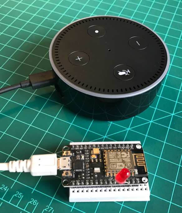
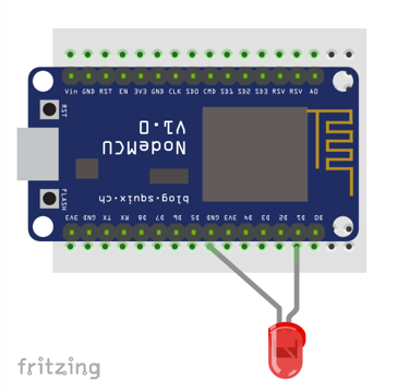
For our first test, let's connect a LED at NodeMCU pin D1 as shown at above diagram.
Open the file Alexa_LED_Control_V2_EXT.ino that you downloaded from my GitHub and change the dummy wifi credentials, with your own:
const char* ssid = "YOUR SSID";
const char* password = "YOUR PASSWORD";
Confirm that you have properly defined the pin where the LED is connect and give a name for your device:
String device_name = "lights";  // Name of device
int relayPin = D1;              // Pin to toggle
In my case, the device will be named "Lights". Here in this example is a single LED, but could be connected to a relay that will turn on the lights of my office.
Upload the code to your NodeMCU.
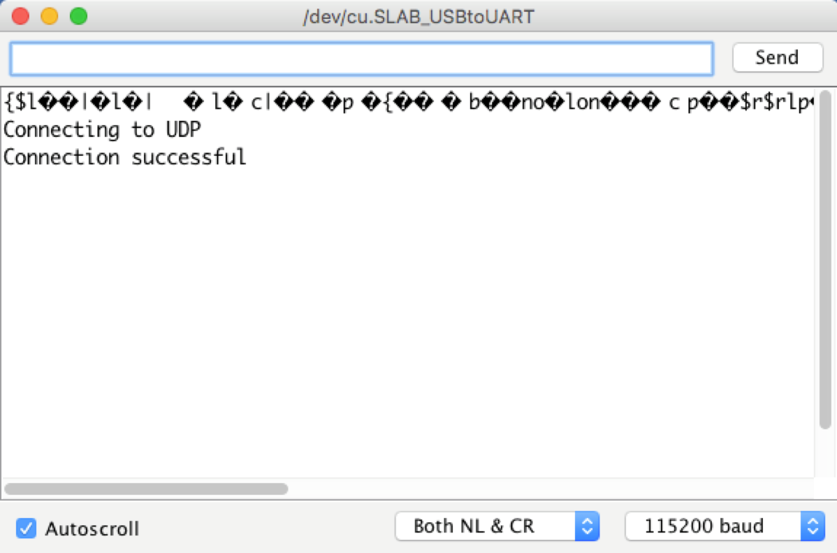
On Serial monitor you can see the message "Connecting to UDP" and "Connection Successful". This means that from NodeMCU's side it all OK.
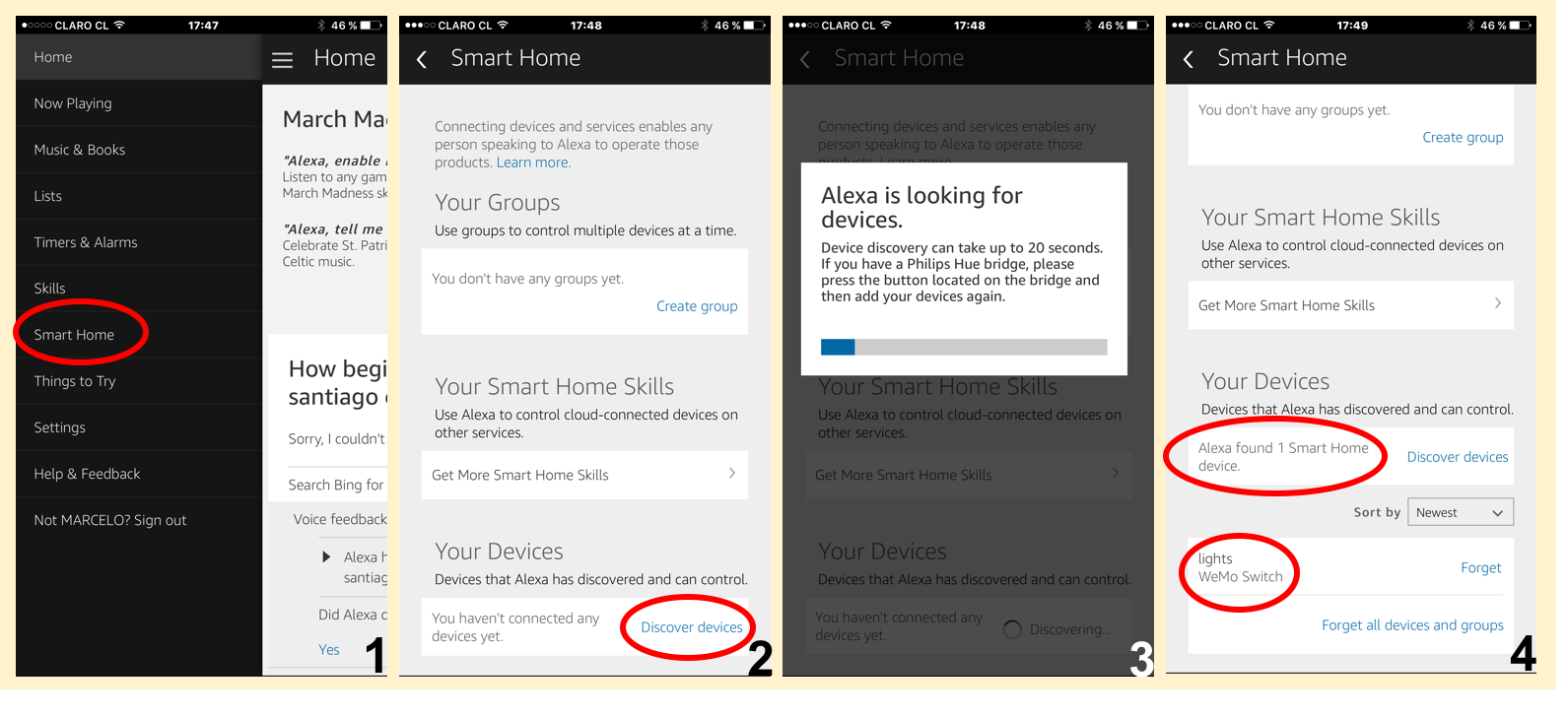
Now, let's ask to Alexa to find your device. There are 2 methods to do it:
- Using the Alexa App in your Smartphone as shown on the photos. In our case, Alexa will find "1 Smart Home device": lights WeMo Switch.
- Asking Alexa to do it directly using voice command, like: "Alexa, Find connected devices" as shown at the video below:
Once Alexa has discovery your device, you can give her voice commands as shown bellow:
Working With Multiple Devices
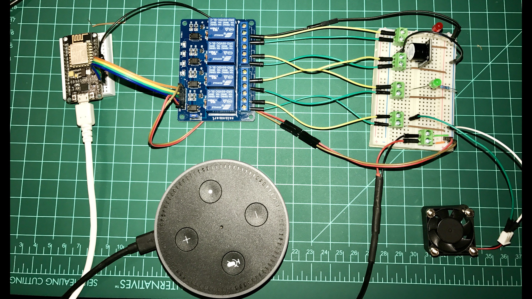
Let's go deeper and develop a more realistic circuit with multiple devices that can be used with home automation.
We will use a 4 Channel relay module to control 2 lamps and 2 outlets. This segment of the project was based on the great tutorial post by Charles Gantt, How To: DIY Home Automation With NodeMCU and Amazon Alexa.
Follow the below instructions:
Connect the Relays inputs with NodeMCU's pins as bellow:
int relayOne = 14;  // NodeMCU pin D5
int relayTwo = 15;  // NodeMCU pin D8
int relayThree = 3; // NodeMCU pin RX
int relayFour = 1;  // NodeMCU pin TX
Our "smart devices" will be 2 fixed Lamps and 2 general Outlets. As you saw on the previous steps, we must emulate "WeMo Devices" and to do that we must name them as below:
- Light One
- Light Two
- Outlet One
- Outlet Two
Next we must define them in our code, so Alexa can understand it. We will also define 2 commands (on and off) and one Port number for each device.
The general format should be:
    lightOne = new Switch("Light One", 80, lightOneOn, lightOneOff);
    lightTwo = new Switch("Light Two", 81, lightTwoOn, lightTwoOff);
    outletOne = new Switch("Outlet One", 82, outletOneOn, outletOneOff);
    outletTwo = new Switch("Outlet Two", 83, outletTwoOn, outletTwoOff);
Now, you must define the 2 functions related with each device condition:
For Lights:
void lightOneOn() {
  Serial.print("Switch 1 turn on ...");
  digitalWrite(relayOne, LOW);   // sets relayOne on
}

void lightOneOff() {
  Serial.print("Switch 1 turn off ...");
  digitalWrite(relayOne, HIGH);   // sets relayOne off
}

void lightTwoOn() {
  Serial.print("Switch 2 turn on ...");
  digitalWrite(relayThree, LOW);   // sets relayTwo on
}

void lightTwoOff() {
  Serial.print("Switch 2 turn off ...");
  digitalWrite(relayThree, HIGH);   // sets relayTwo Off
}
And for Outlets:
void outletOneOn() {
  Serial.print("Socket 1 turn on ...");
  digitalWrite(relayFour, LOW);   // sets relayThree on
}

void outletOneOff() {
  Serial.print("Socket 1 turn off ...");
  digitalWrite(relayFour, HIGH);   // sets relayThree off
}

void outletTwoOn() {
  Serial.print("Socket 2 turn on ...");
  digitalWrite(relayTwo, LOW);   // sets relayFour on
}

void outletTwoOff() {
  Serial.print("Socket 2 turn off ...");
  digitalWrite(relayTwo, HIGH);   // sets relayFour off
}
In my case here I choose to test the 4 WeMo smart switches with devices powered with external 5 VDC. Once we have relays, we could have any type of real devices as TVs, refrigerators, etc.
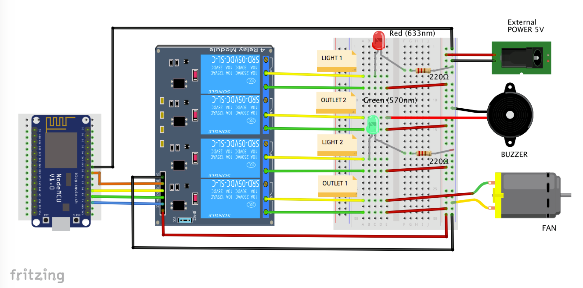
- As "Light 1", we will use a Red LED
- As "Light 2", we will use a GREEN LED
- As Outlet 2, we will use a small buzzer (you can imagine a Radio or a TV! ;-)
- As Outlet 1, we will use a small 5V fan
Follow the above electrical diagram to finish the HW connection.
Download the complete code: NODEMCU_ALEXA_WeMos_4X_Serial_Monitor_EXT.ino from my GitHub.
Change the dummy wifi credentials, with your own:
const char* ssid = "YOUR SSID";
const char* password = "YOUR PASSWORD";
And that's it!.
Follow the same procedure as defined on previous step to let Alexa find your 4 devices.
The video below shows a demo of this step:
Home Automation
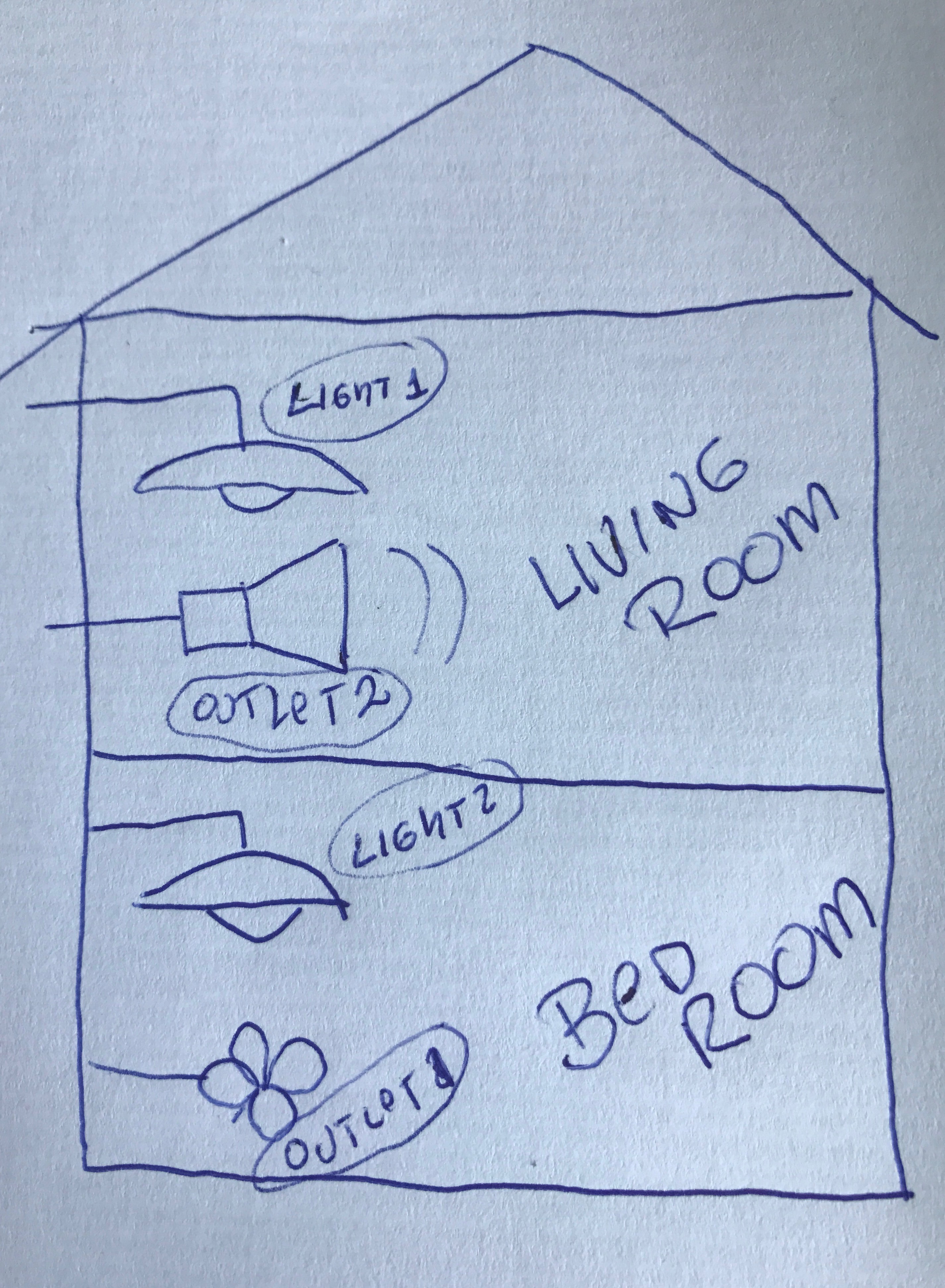
Now we have 4 smart devices working properly that can be individually turned on and off. But suppose that we want to group our devices to be used on our home. What should be done?
For example, suppose that our home has 2 rooms:
- Bed Room
- Living Room
Now, suppose that you want to have one lamp and one outlet in each room. So, let's group our 4 devices as shown at the introduction block diagram:
- Bed Room
- Light 2
- Outlet 1 (Fan)
- Living Room
- Light1
- Outlet 2 (Buzzer)
We will also to create another group to deal with all devices at same time, turning on/off all device at same time.
So, let's create a version 2 of our code were "3 new switches" should now be identified by Alexa, adding the following steps to our code:
1. Switch's definition:
Switch *allDevices = NULL;
Switch *bedRoom = NULL;
Switch *livingRoom = NULL;
2. Group of devices on/off callbacks declaration:
void allDevicesOn();
void allDevicesOff();
void bedRoomOn();
void bedRoomOff();
void livingRoomOn();
void livingRoomOff();
3. Now, at setup(), let's associate the switches with the new callbacks and Ports (remember that we have a maximum of 14 devices that can be handled with this code):
    allDevices = new Switch("All Devices", 84, allDevicesOn, allDevicesOff);
    bedRoom = new Switch("Bed Room", 85, bedRoomOn, bedRoomOff);
    livingRoom = new Switch("Living Room", 86, livingRoomOn, livingRoomOff);
4. Adding Switches upnp Broadcast Responder at setup():
    upnpBroadcastResponder.addDevice(*allDevices);
    upnpBroadcastResponder.addDevice(*bedRoom);
    upnpBroadcastResponder.addDevice(*livingRoom);
5. Append the lines to loop():
    allDevices->serverLoop();
    bedRoom->serverLoop();
    livingRoom->serverLoop();
6. And finally, let's create the proper group devices functions to react when Alexa receives a voice command:
void allDevicesOn()
{
  Serial.print("All Devices turn on ...");
  digitalWrite(relayOne, LOW);   // sets relay1 on
  digitalWrite(relayTwo, LOW);   // sets relay2 on
  digitalWrite(relayThree, LOW);   // sets relay3 on
  digitalWrite(relayFour, LOW);   // sets relay4 on
}

void allDevicesOff()
{
  Serial.print("All Devices turn off ...");
  digitalWrite(relayOne, HIGH);   // sets relay1 off
  digitalWrite(relayTwo, HIGH);   // sets relay2 off
  digitalWrite(relayThree, HIGH);   // sets relay3 off
  digitalWrite(relayFour, HIGH);   // sets relay4 off
}

void bedRoomOn()
{
  Serial.print("Bed Room turn on ...");
  digitalWrite(relayThree, LOW);   // sets relay3 on
  digitalWrite(relayFour, LOW);   // sets relay4 on
}

void bedRoomOff()
{
  Serial.print("Bed Room turn off ...");
  digitalWrite(relayThree, HIGH);   // sets relay3 off
  digitalWrite(relayFour, HIGH);   // sets relay4 off
}

void livingRoomOn()
{
  Serial.print("Living Room turn on ...");
  digitalWrite(relayOne, LOW);   // sets relay1 on
  digitalWrite(relayTwo, LOW);   // sets relay2 on
}

void livingRoomOff()
{
  Serial.print("Living Room turn off ...");
  digitalWrite(relayOne, HIGH);   // sets relay1 off
  digitalWrite(relayTwo, HIGH);   // sets relay2 off
}
The above procedure should be follow for any adicional device or group of devices that you want to add to your project.
You can download the complete code from my GitHub:
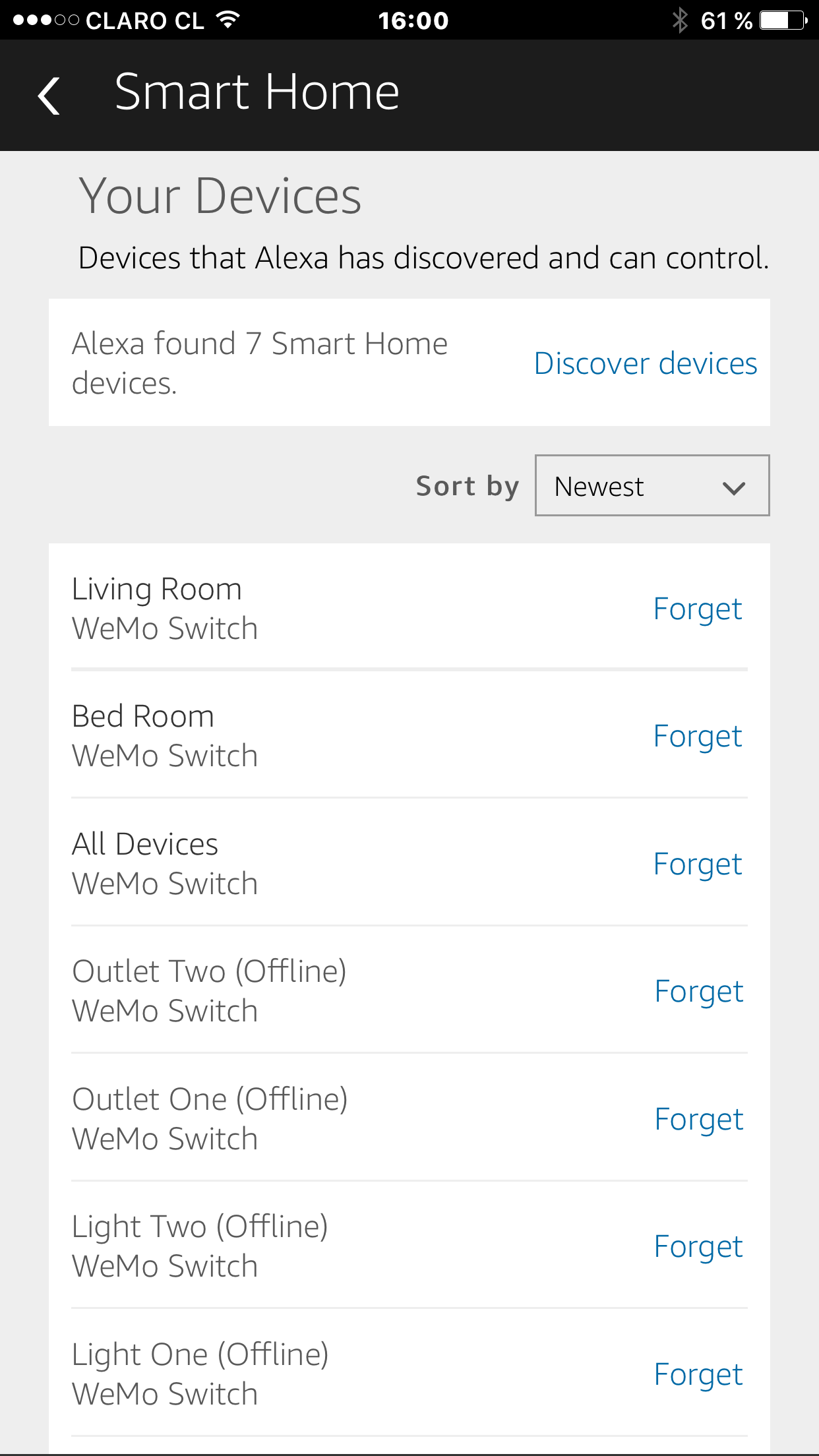
After the code is uploaded to NodeMCU, it is time to ask Alexa to "FIND DEVICES". As explained before, you can do it using a voice command or the Alexa App. On both cases, the result can be verified at app as shown above. Seven devices ("WeMo Switches") should be found now by Alexa:
- Living Room
- Bed Room
- All Devices
- Outlet One
- Outlet Two
- Light One
- Light Two
The video below shows how our complete Home Automation project will work:
Conclusion
As always, I hope this project can help others find their way in the exciting world of electronics and IoT!
Please visit my GitHub for updated files:
Home-Automation-with-Alexa-and-NodeMCU
For more projects, please visit my blog: MJRoBot.org
Saludos from the south of the world!
See you at my next instructable!
Thank you
Marcelo