WebApp Puzzle LED Lamp With ESP32
by NicolasB50 in Circuits > LEDs
3550 Views, 19 Favorites, 0 Comments
WebApp Puzzle LED Lamp With ESP32
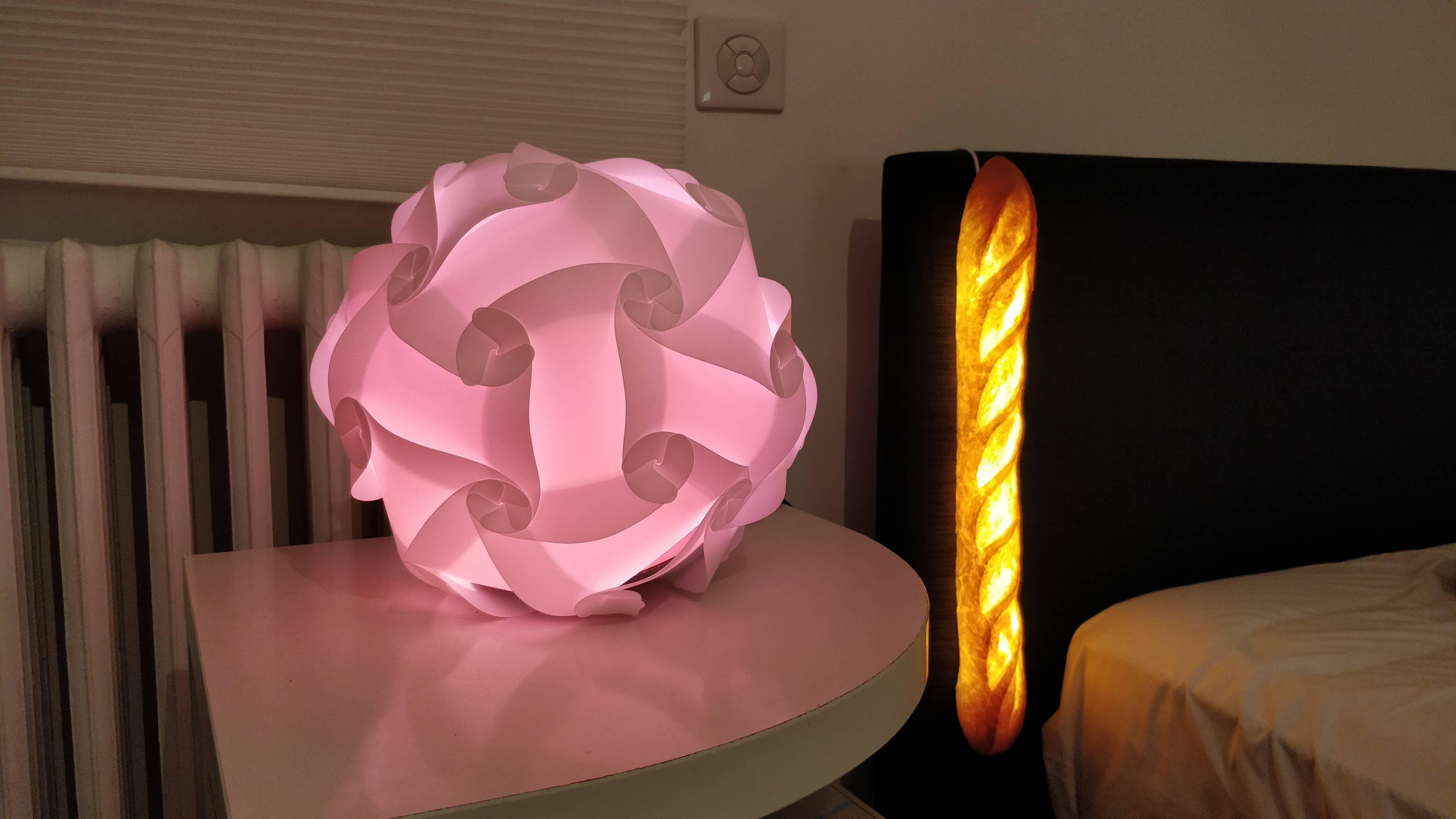
I've been playing around with LED strips for years, and recently moved into a friend's place where I couldn't make big changes like mount the strip on the walls, so I put together this lamp that has a single wire coming out for power and can be placed on any surface or hung upside-down.
In this project, I use very few parts and recycle cardboard where I can.
I didn't write the firmware for the microcontroller as the one I found on Github was very well done, but I will explain how to install it (which the Github is lacking).
Buying everything on the supplies list comes up to about $70, not low-cost! But if you're doing electronics projects then you should have a lot of these already or will use these in future projects.
Disclaimer: Wrote this for the LED Strip Speed Challenge, please go and vote!
Supplies
- IQ Puzzle Lampshade (or make your own!) - $8.99 or less
- Addressable LED Strip (This one is 1 meter with 60 LEDs, I use 1 meter with 30 LEDs in mine) - $10.99
- ESP32-based microcontroller development board - $14.99 (2-pcs)
- Logic-level voltage shifter - $7.49 (10-pcs)
- Female 0.1" header cables
- 5V power supply (12A = enough to power 200+ LEDs)
- 2-lead wire
- Toilet paper roll
- Flat cardboard
Assemble the Lampshade

.JPG)
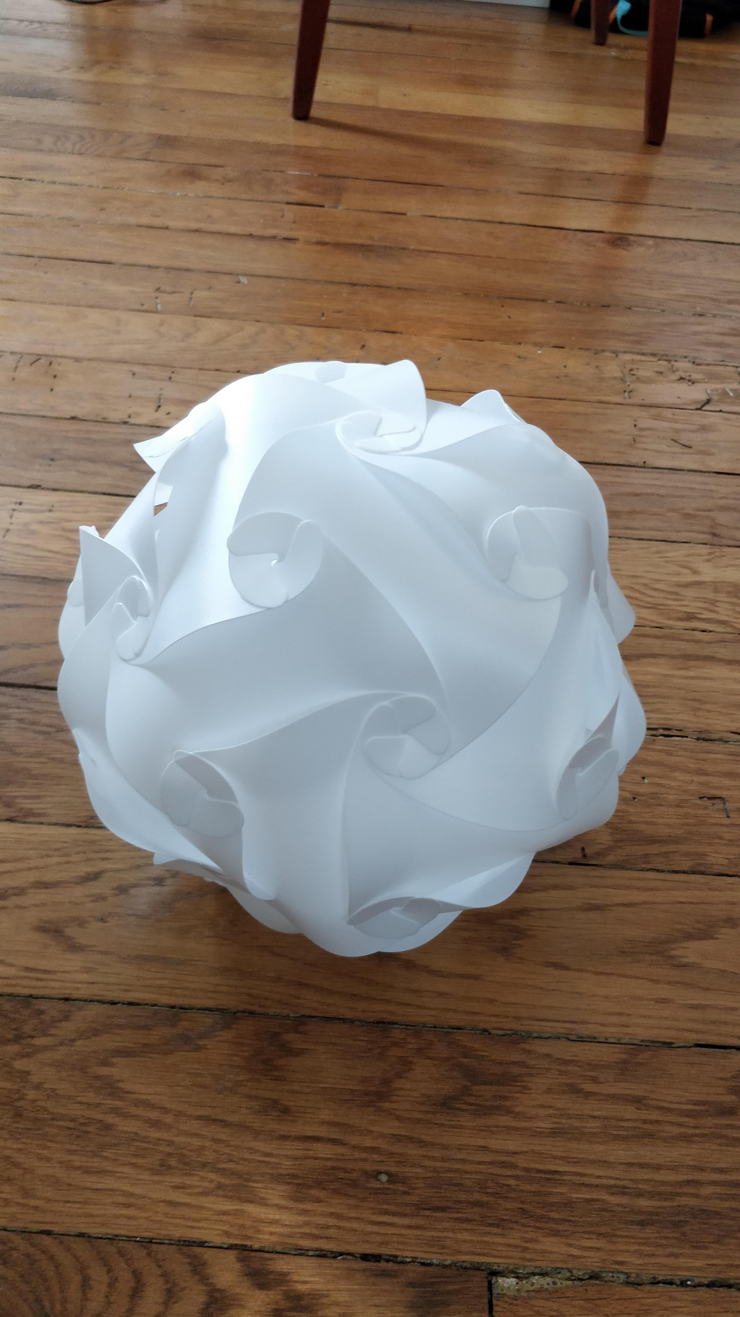
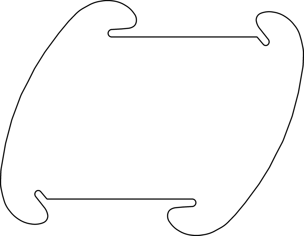
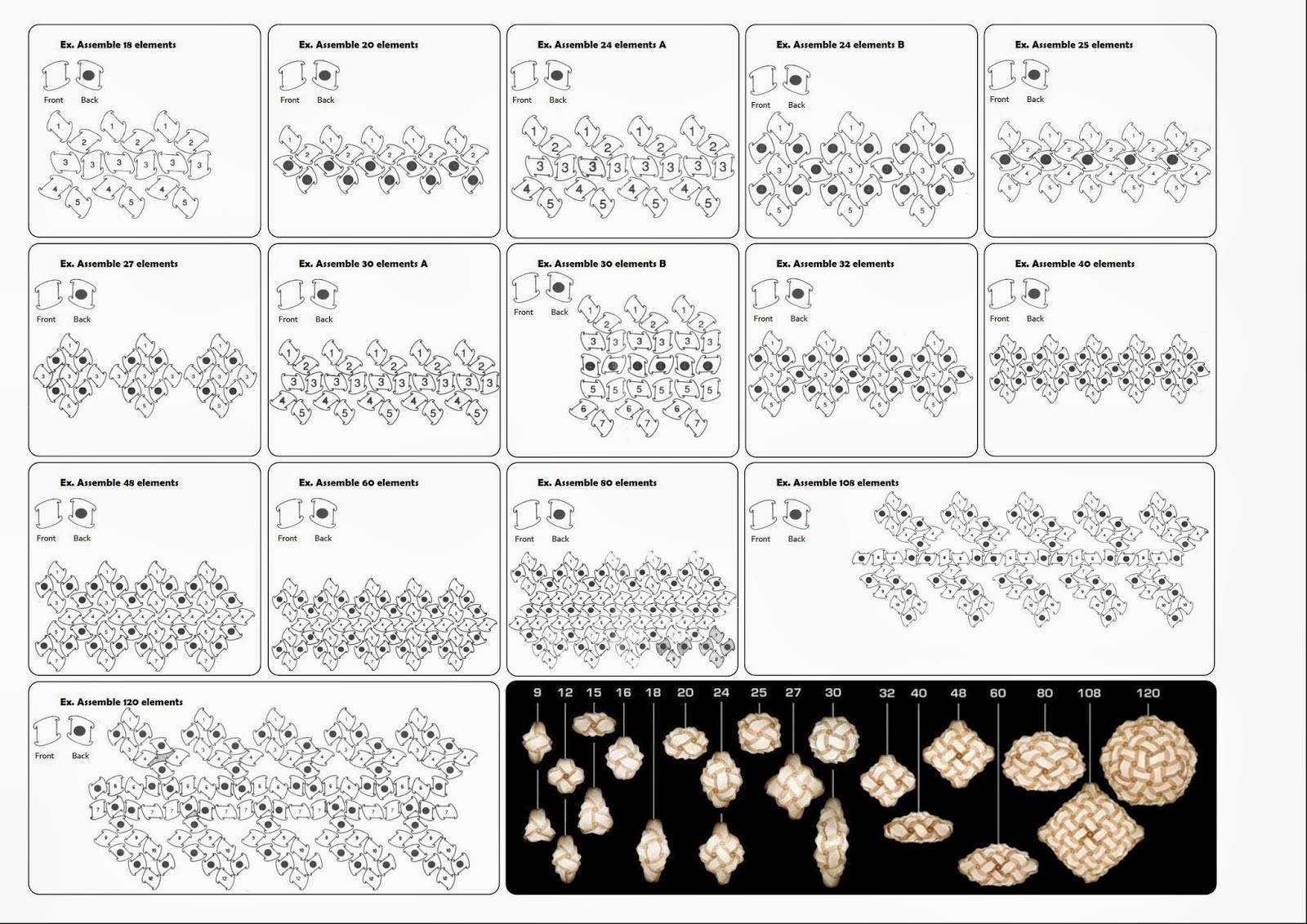
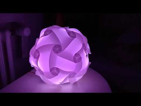
This is a fun lampshade that I've seen in some boutiques, and I found a kit online for about $10 (Amazon link). These can be made at home as well by making a stencil with the pattern provided in the pictures or laser cut for more accuracy. I made the standard design with 30 pieces, but would love to see some interesting shaped ones! If you make the pieces at home, I recommend using a flexible and durable material as the puzzle pieces are bent quite a bit when assembled. I also recommend using a white translucent material as this will let through the true color of the LEDs and diffuse the lights for a cool effect.
There are a few instructables on how to make your own puzzle lamps, I liked this one.
Wire Up the Controller
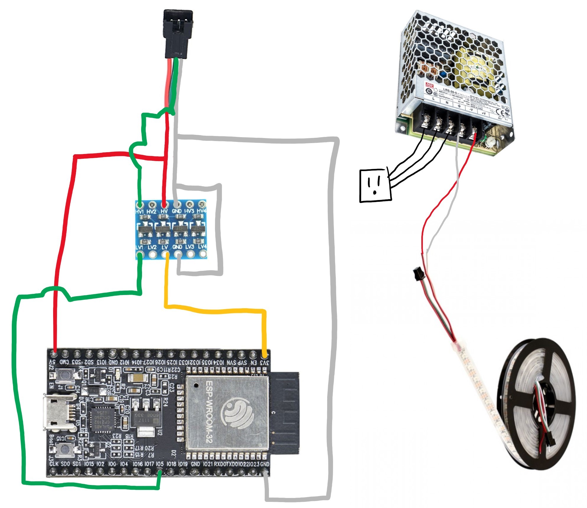
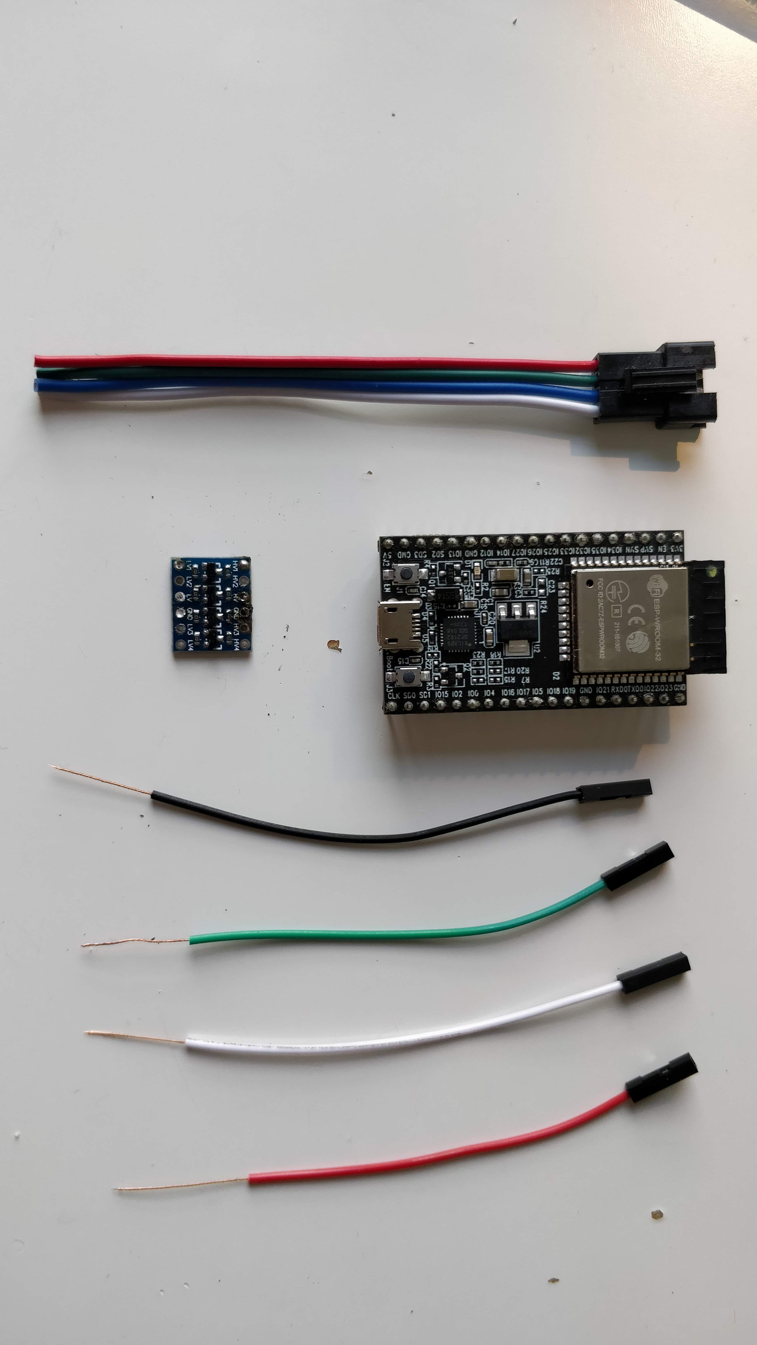
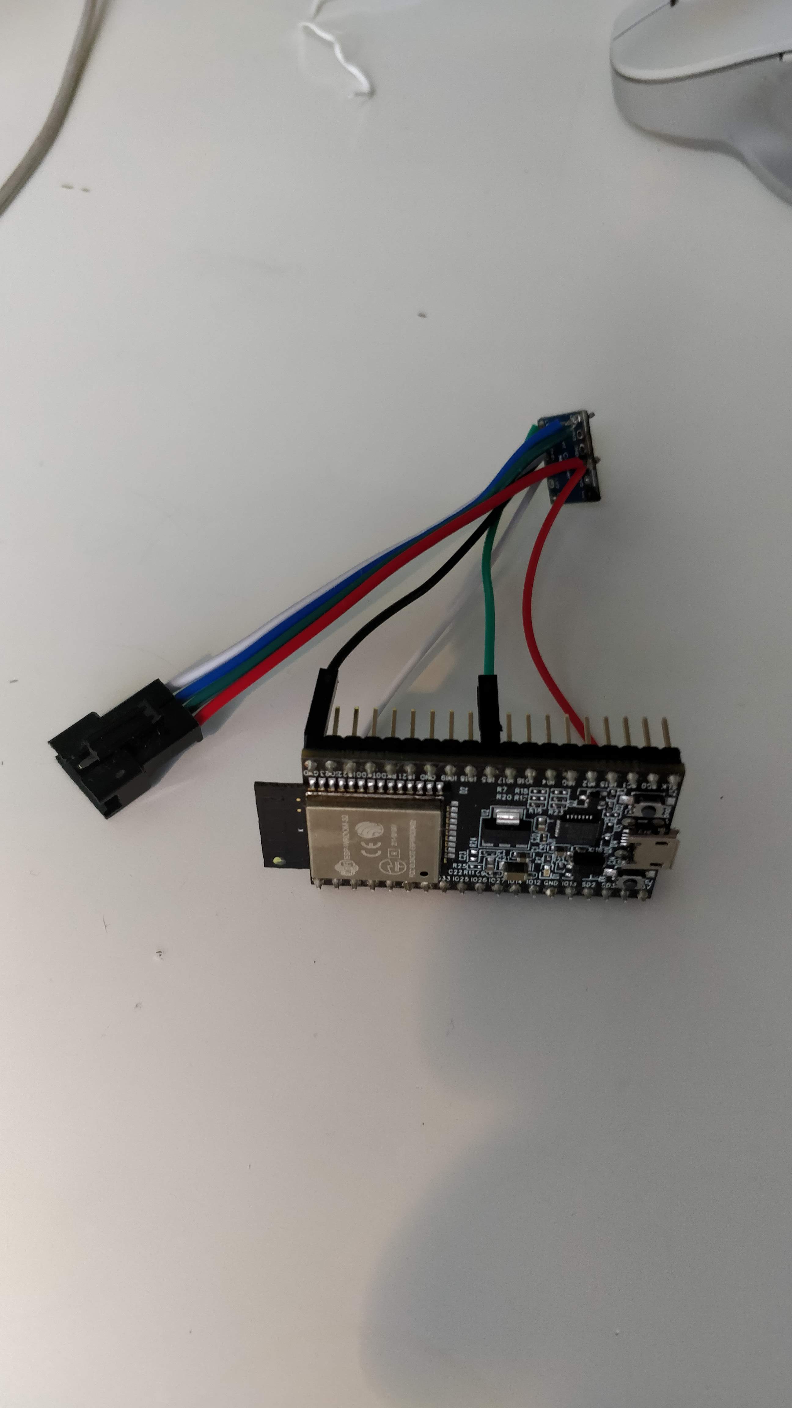
Now let's wire up the microcontroller to the LED strip plug.
The LED strip I use requires a 5V signal and the ESP32 outputs 3.3V, so to avoid any possible issues I use a logic level voltage shifter which takes the high-voltage (5V) reference from the power supply (wired through the LED strip connector) and the low-voltage (3.3V) reference from the ESP32 on-board voltage regulator.
See the drawing for more information on how to wire the entire system.
I use female header cables and splice them with the LED plug where I can to reduce the number of connections I need to solder.
You can use any 5V power supply for this project, but I recommend getting one like what I link to, as it has plenty of power and can be used for lots of projects (see 2nd note).
Notes:
- On safety: Be VERY CAREFUL when dealing with mains power!!! Always disconnect the cable from the wall before messing about with anything near the power connections, and be sure to close the plastic lid over the connectors before putting it away. Always follow proper precautions and ensure the plug is correctly wired up before plugging it in! Here is a guide to color codes for wiring up the Line (L), Neutral (N), and Ground (⏚) on your power supply)
- On power consumption: This type of LED strip will use about 60mA per LED at max brightness, so consider this when selecting your power supply. The strip I link to in the 1st step has 60 LEDs, so the current requirement is 60*60mA=3600mA=3.6A. To get the power requirement, we use Watts=Volts*Amps so 3.6A*5V=18W. This is not much, and the microcontroller uses very little (>1/4W), but this can increase quickly with a longer strip or more LEDs per meter.
Mount the LEDs
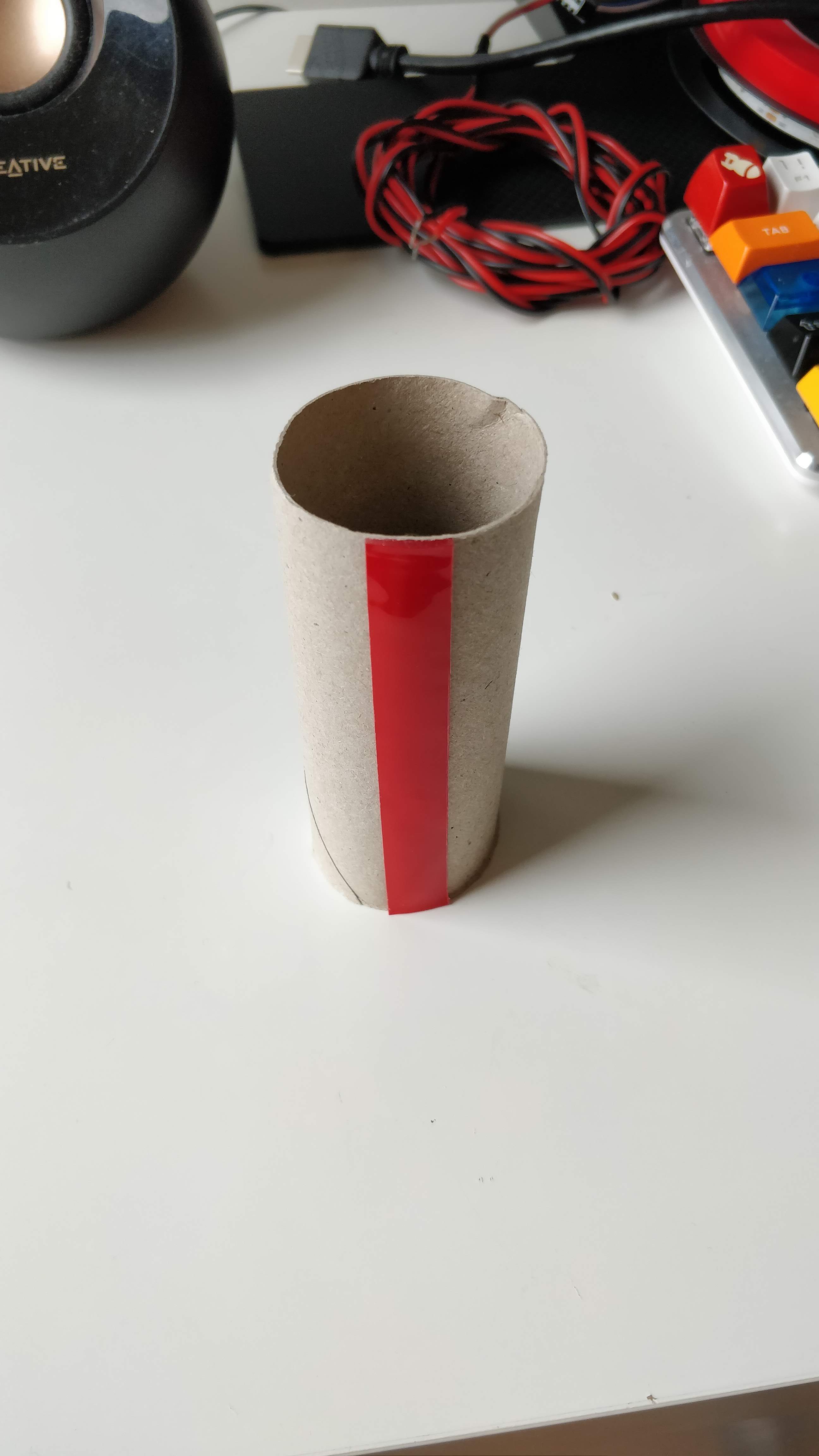
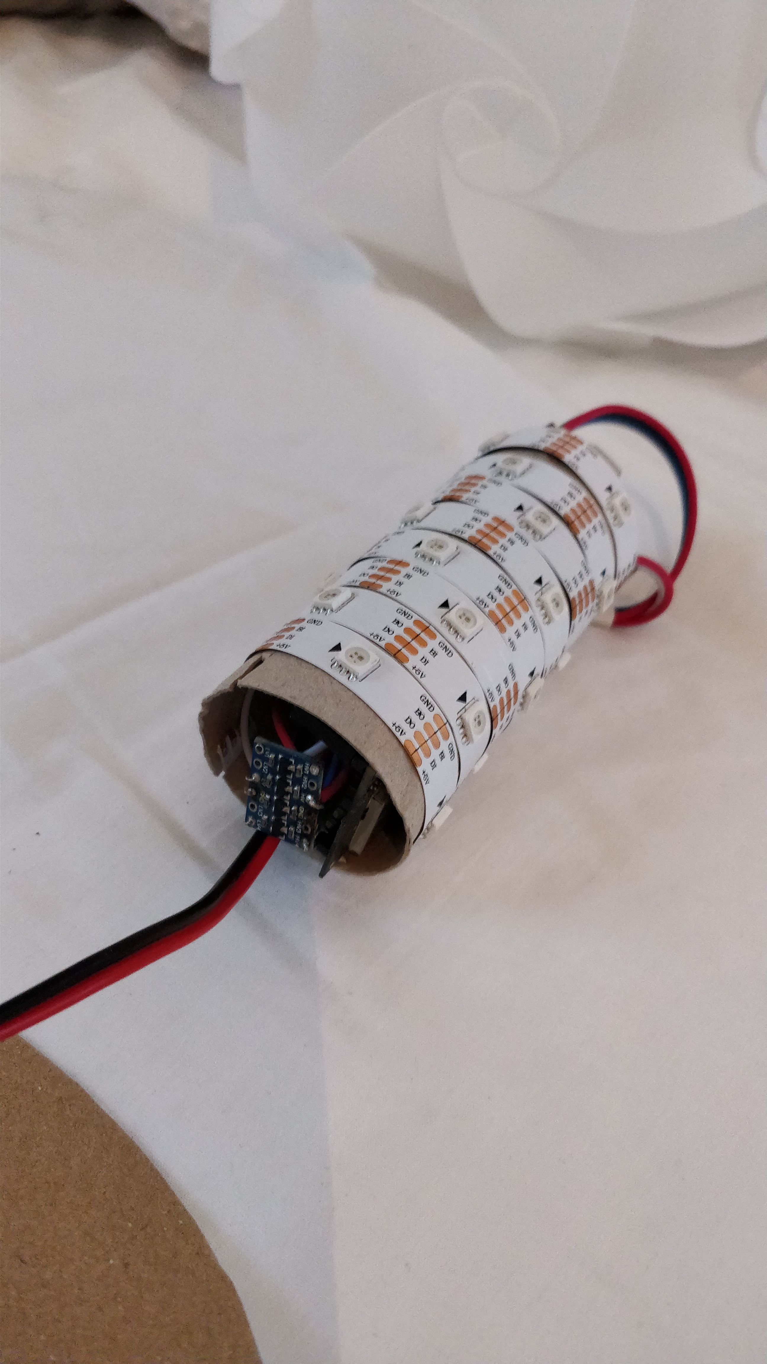
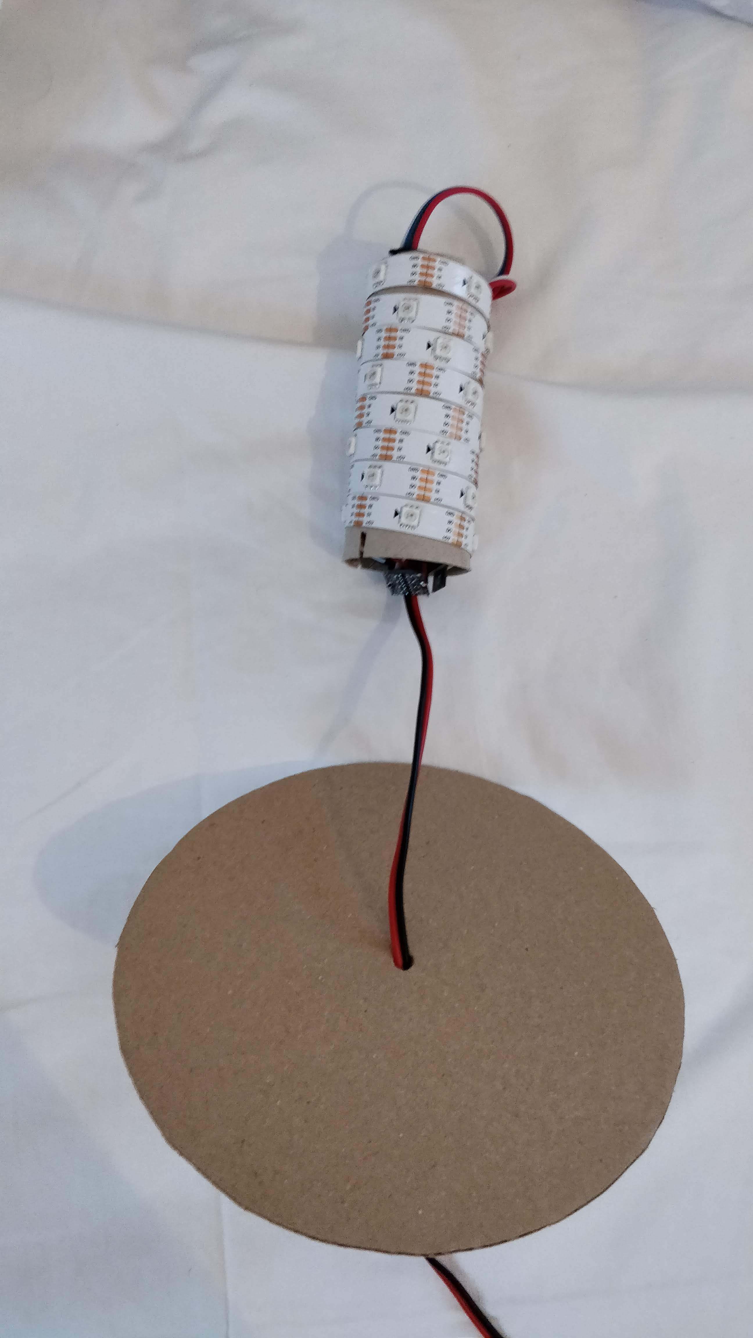
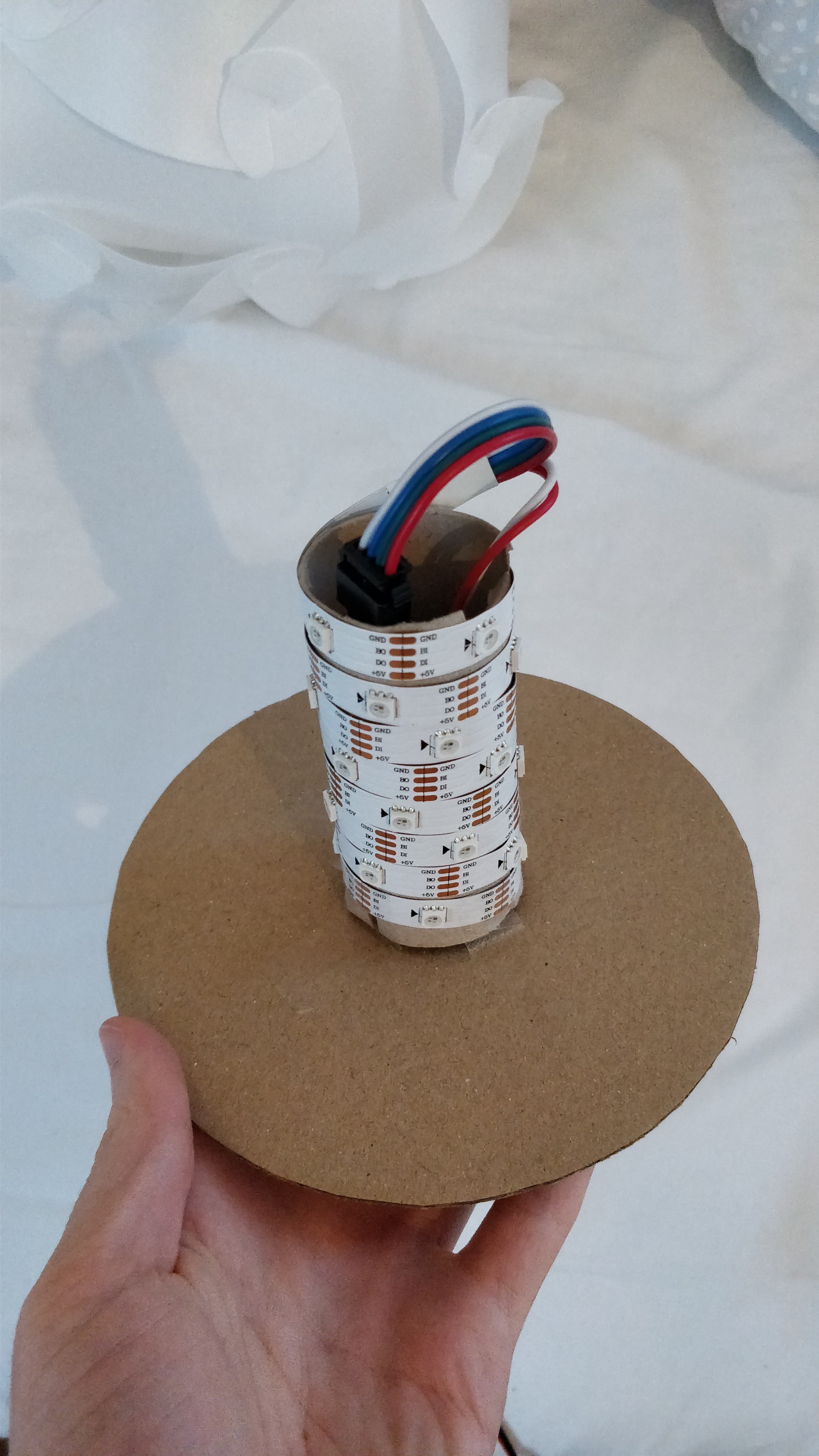
To get the LEDs to evenly illuminate the lampshade, I wrapped them around a toilet paper tube. I secured them on there with a strip of double-sided glue, and put the plug through the tube with the microcontroller and voltage shifter hidden away in there.
I made a cardboard disc to keep the tube centered and upright inside the ball, I made it approximately 6in (15cm) diameter and it works well with my lampshade. I then strung the power cable through the center and connected it to the power supply.
Note: you should leave the tube unsecured to the disc before getting the firmware uploaded (next step) so that you can debug and get the IP address through the serial monitor.
Set Up the Controller Firmware



Set up the Arduino IDE on your computer and then add the ESP32 board:
- Start Arduino and open Preferences window.
- Enter the release link below into Additional Board Manager URLs field. You can add multiple URLs, separating them with commas.
- Open Boards Manager from Tools > Board menu and install esp32 platform (use the search box).
- Close the Arduino IDE for the next steps
Download the repositories from Github:
- Firmware: https://github.com/jasoncoon/esp32-fastled-webserv...
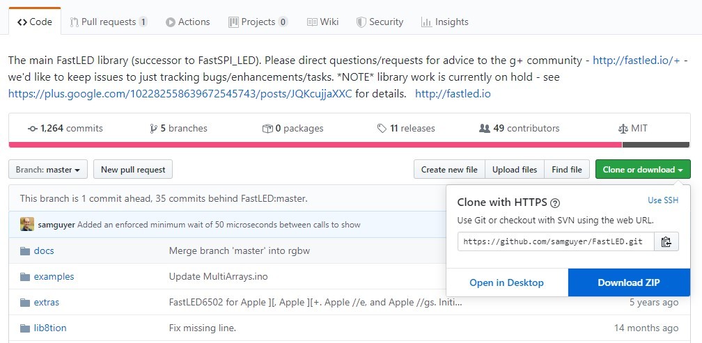
- Sam Guyer fork of FastLED: https://github.com/samguyer/FastLED
- Note: Make sure to use this version of FastLED, the main fork that's available from the library manager in the Arduino IDE doesn't work for ESP32 boards!
- Arduino ESP32FS Plugin: https://github.com/me-no-dev/arduino-esp32fs-plugi...
Put the repos in the right places:
- Unzip all the downloaded repositories
- Rename esp32-fastled-webserver-master to esp32-fastled-webserver (just remove '-master' at the end) and move it to your Arduino sketchbook folder
- Move the FastLED folder into your 'libraries' folder in your sketchbook folder
- Create the 'tools' folder in your sketchbook folder if it doesn't yet exist and move the ESP32FS folder into it
Reopen Arduino IDE and set up the firmware:
- Open the downloaded sketch (File > Sketchbook > esp32-fastled-webserver)
- In the 1st tab (esp32-fastled-webserver), edit lines 72-81 and 192-205 as detailed in the pictures (this sets up how many LEDs you have and where they are wired to the microcontroller)
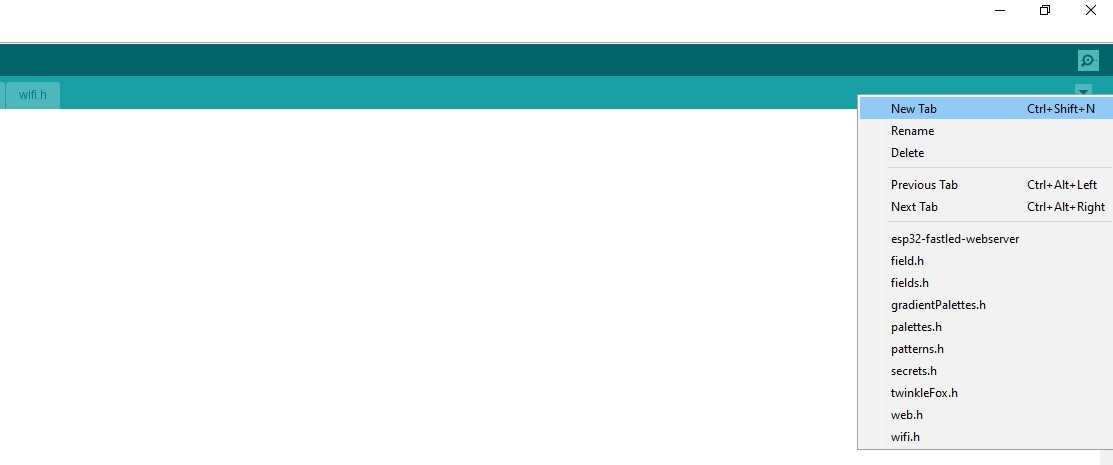
- Create a new tab and name it secrets.h, then copy in your Wi-Fi info as shown in the pics
Upload to the ESP32:
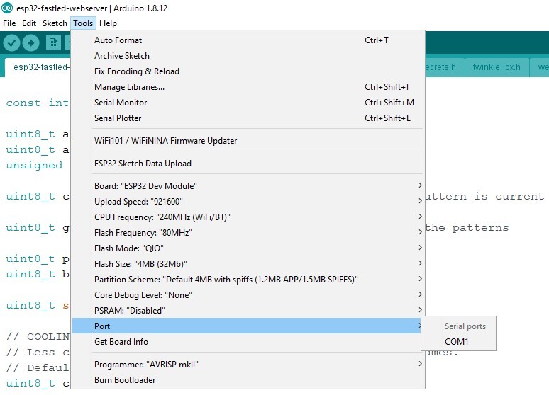
- Select your board (picture 7)
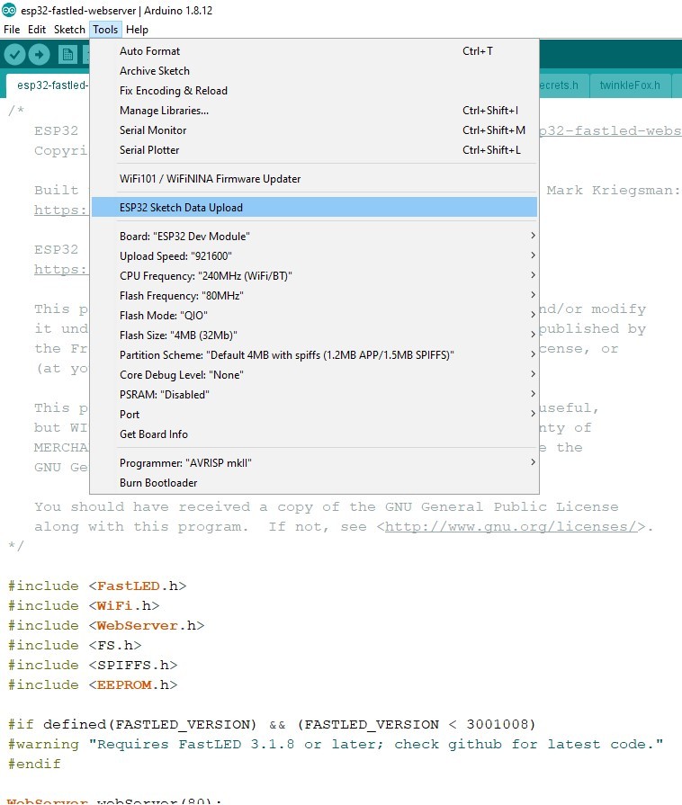
- Upload the data file using the ESP32FS tool we installed (picture 8)
- Open your serial monitor and set the baud rate on the bottom right to 115200 baud
- Upload your sketch to the board and observe setup through the serial monitor
Test, Assemble, and Enjoy!
)
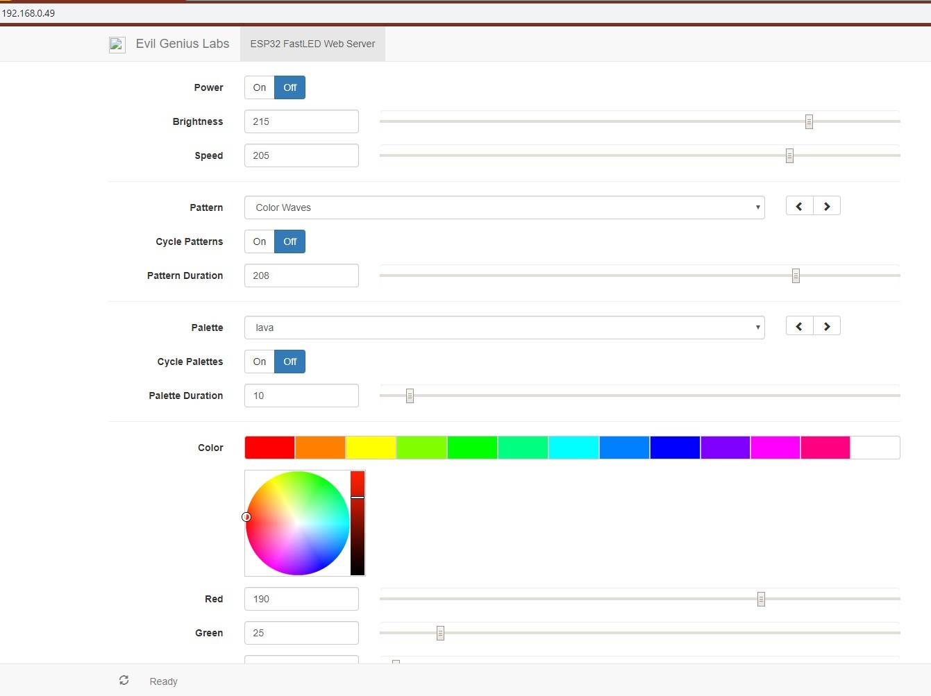
Once your board tells you the IP address, you can visit this address by typing it into your address box (should be something like '192.168.0.15') and if you followed all the steps correctly, the page should load and you can control the LEDs!
If something is not working, try checking your edits to the firmware and reuploading to the board.
Now unplug the board and finish assembling the lamp by fitting the ESP32 and voltage shifter in the tube and taping the tube to the disc with the power cable going out the bottom.
Connect the power cable to the power supply and fit the disc with tube into the lampshade ball so that it sits nice and centered. Reassemble the lampshade with the power cable coming out of the bottom (or top, if you plan on hanging it from your ceiling!).
Turn on the power and watch your lamp come to life! Log into the server again (should be the same address if you don't take too long to reassemble) and take control of your creation! Play with different patterns
Note on server address: Your Wi-Fi router can reassign the address if you turn off the lamp, so if you're no longer able to connect to it you can do a network scan and find the IP address of your ESP32 (I use Fing on my phone to scan and the ESP32 shows up as Espressif).
Enjoy!
Huge shout-out to those that made all this possible: Jason Coon, Sam Guyer, Espressif, and Me No Dev