Web-app Controlled Lighting
by Brandon Wood in Circuits > Arduino
5788 Views, 74 Favorites, 0 Comments
Web-app Controlled Lighting
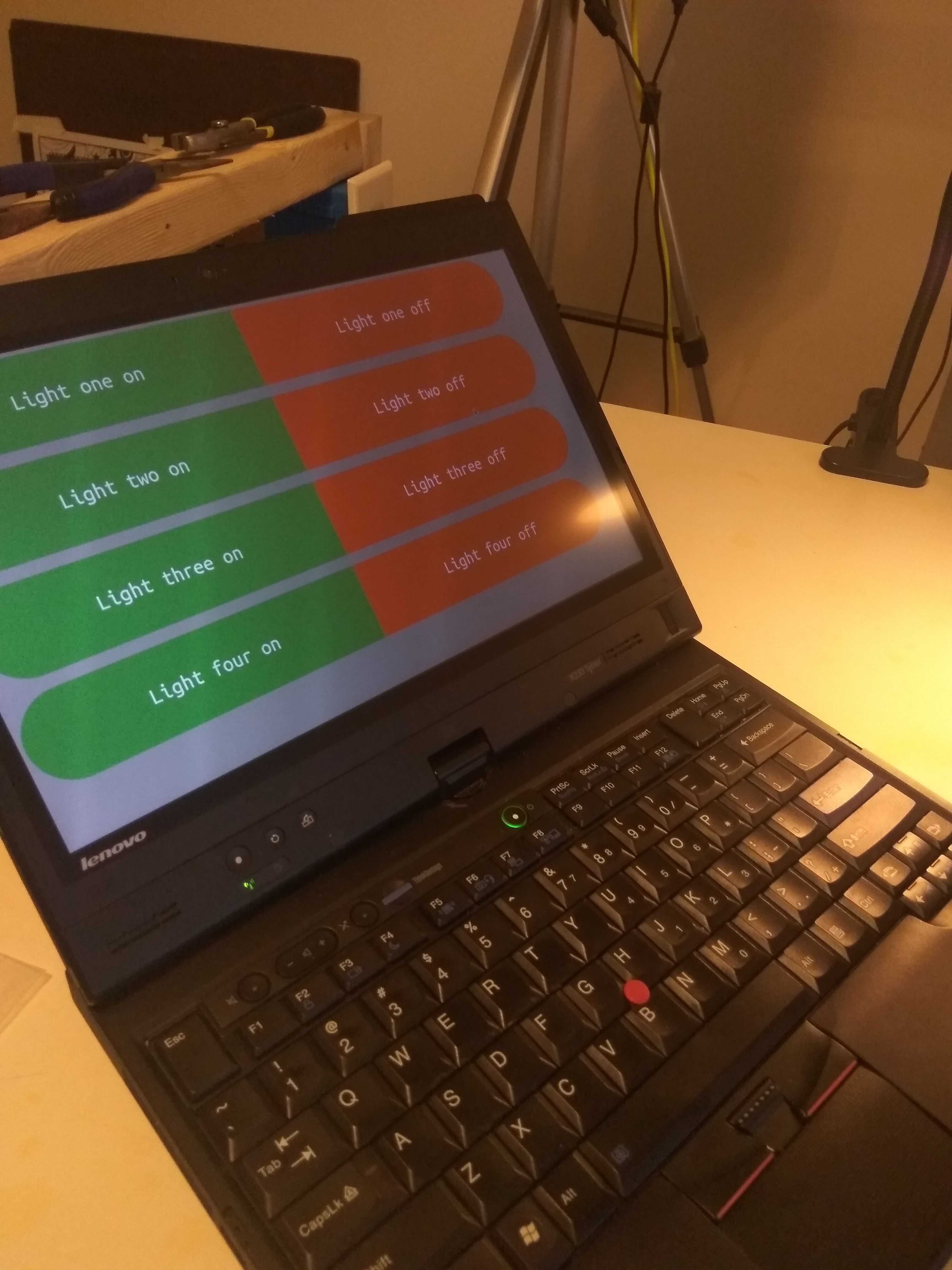
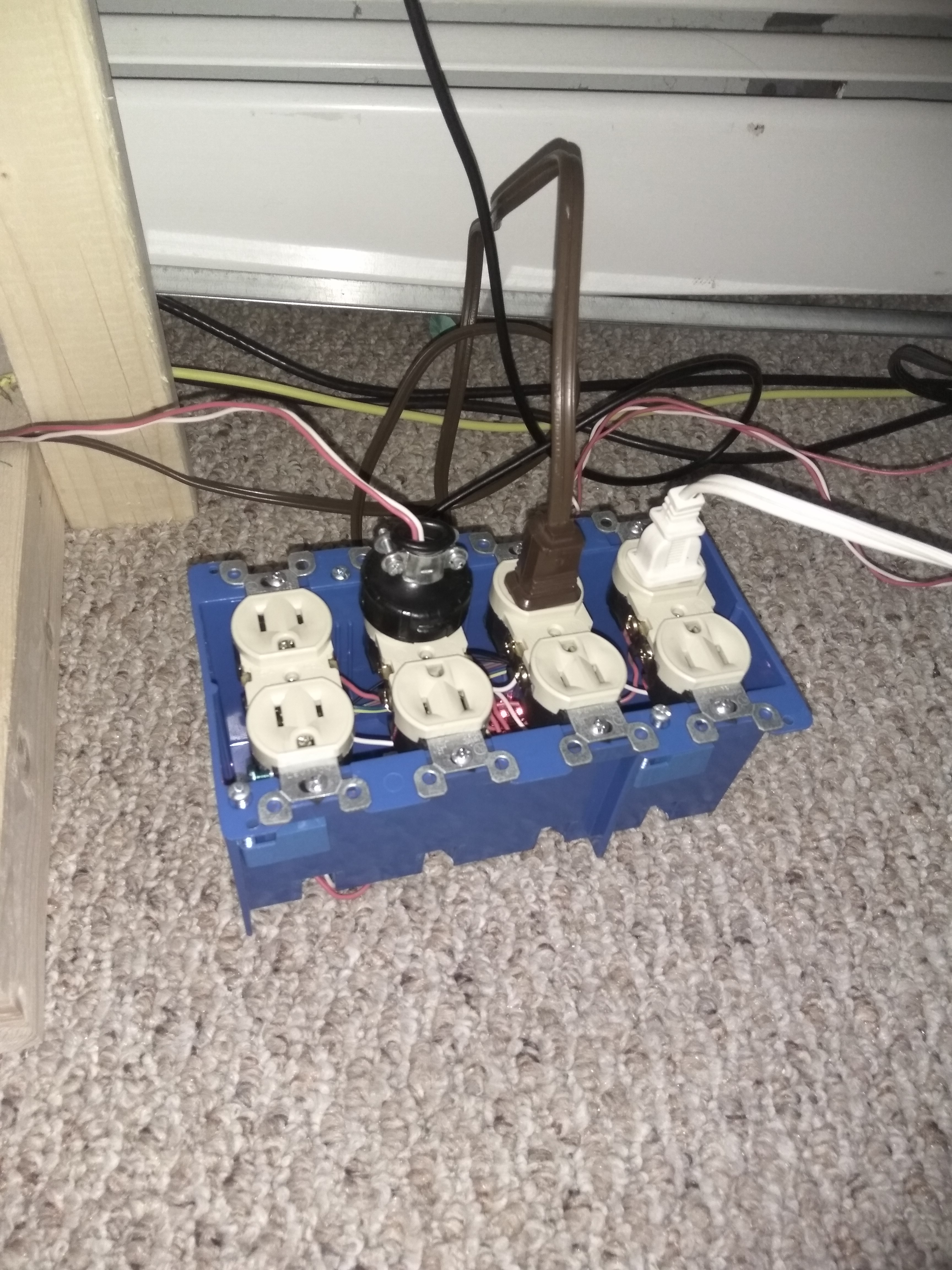
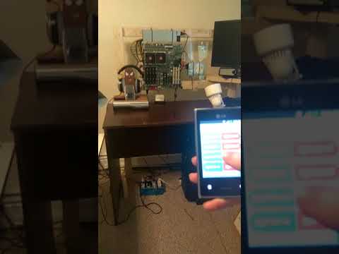
This is an instructable on how to create computer/voice controlled lights. The idea is to use a microcontroller (I use a Sparkfun Promicro in this tutorial but any smaller board with a 5v VCC, microusb and at least 4 gpios can be made to work) to power and control relays inside an outlet box. The microcontroller is manipulated via serial writes (in Python) from an always-on Linux server that acts as the web server for a web-based application. This tutorial assumes that you are familiar with; residential electrical wiring, simple microcontrollers, soldering, basic tools (drills, screwdrivers, etc), Linux (Debian) and Python programming.
DISCLAIMER: I am not advocating you put yourself in any sort of danger or at risk. Residential electrical current can hurt or kill you. Improperly configured wiring could spark and start life altering fires. I am creating this for educational purposes only. Please be advised.
Tools and Parts Necessary
Tools:
- Soldering Iron
- Solder
- Pliers
- Wire Strippers
- 20 Gauge Electrical wire
- Electric Drill
- Phillips Tipped Screwdriver
- Test Lights
- Electrical Tape
Parts:
-
Microcontroller (Sparkfun Promicro
-
4-Gang Junction Box (Plastic)
-
4X Basic Receptacles
-
2X Wire Caps
-
Zip Ties (Small)
-
1 Residential extension cord plug (male)
-
5v Relay (4 Relay Board, ensure you get a board with built in transistors to protect your Microcontroller, thanks to MaximilianK5)
-
Usb to Microusb Wire (Long)
-
Linux Server (With internet Connection)
Setup Microcontroller
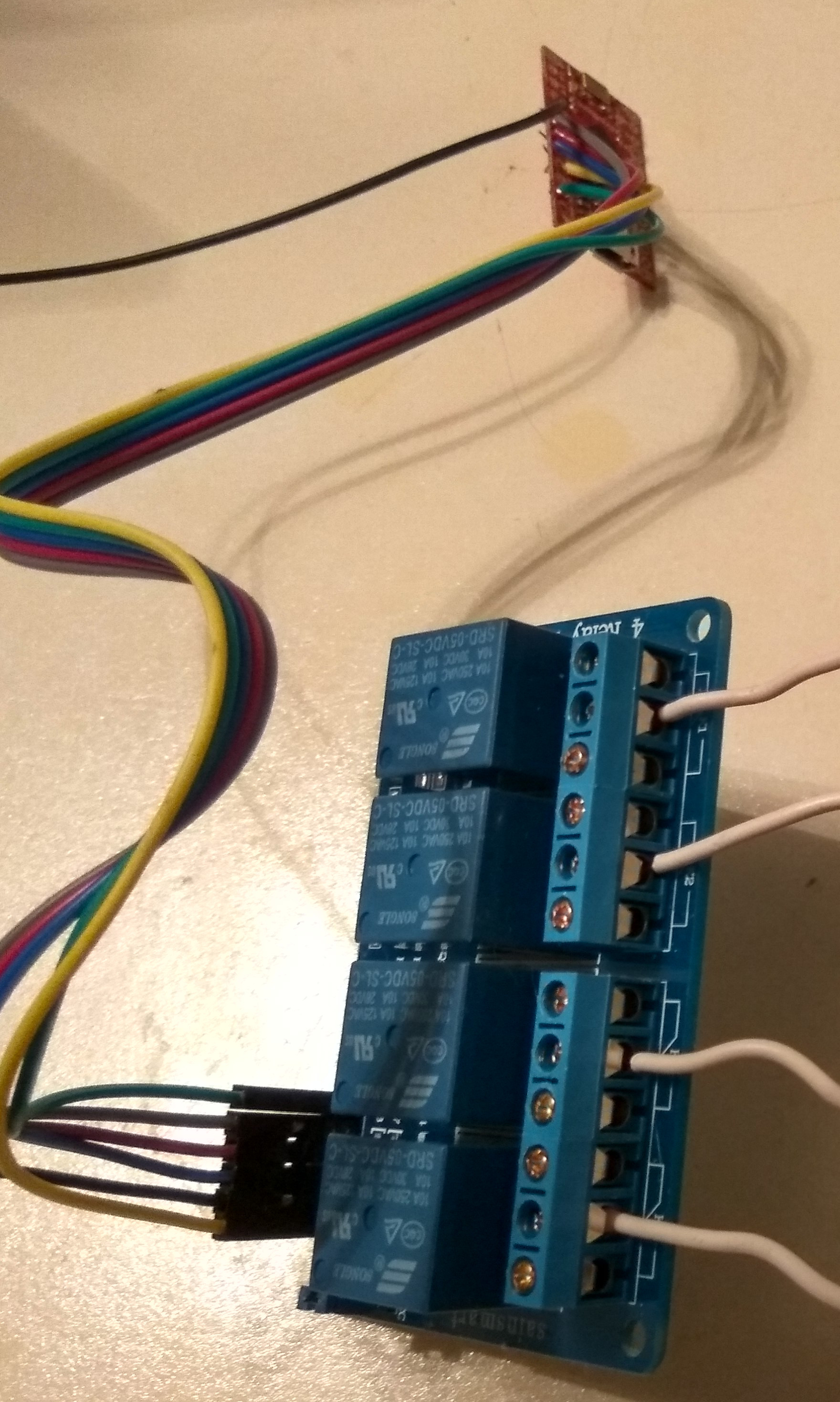
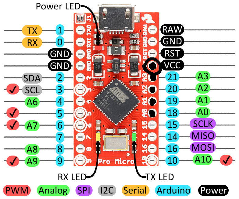
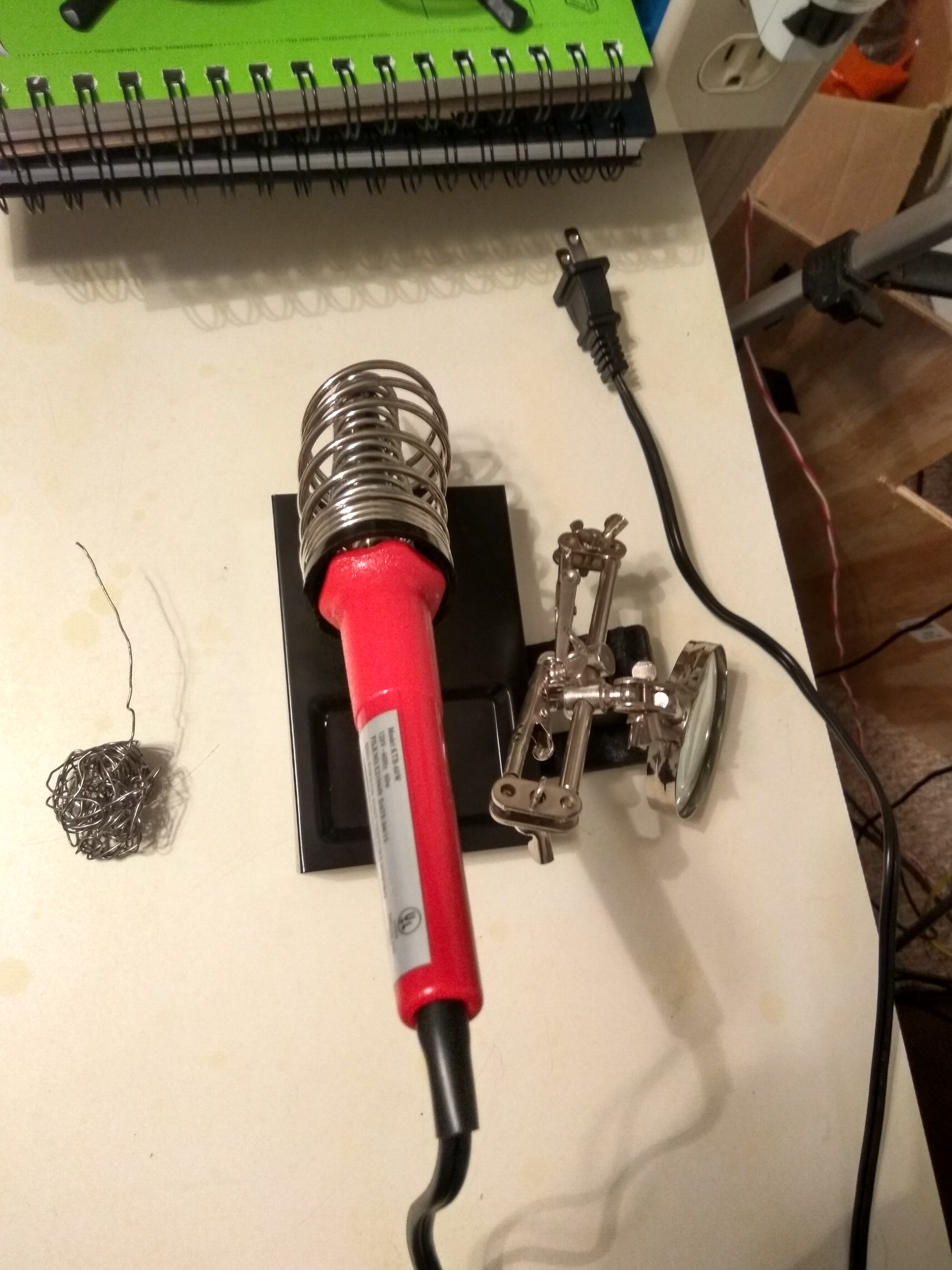
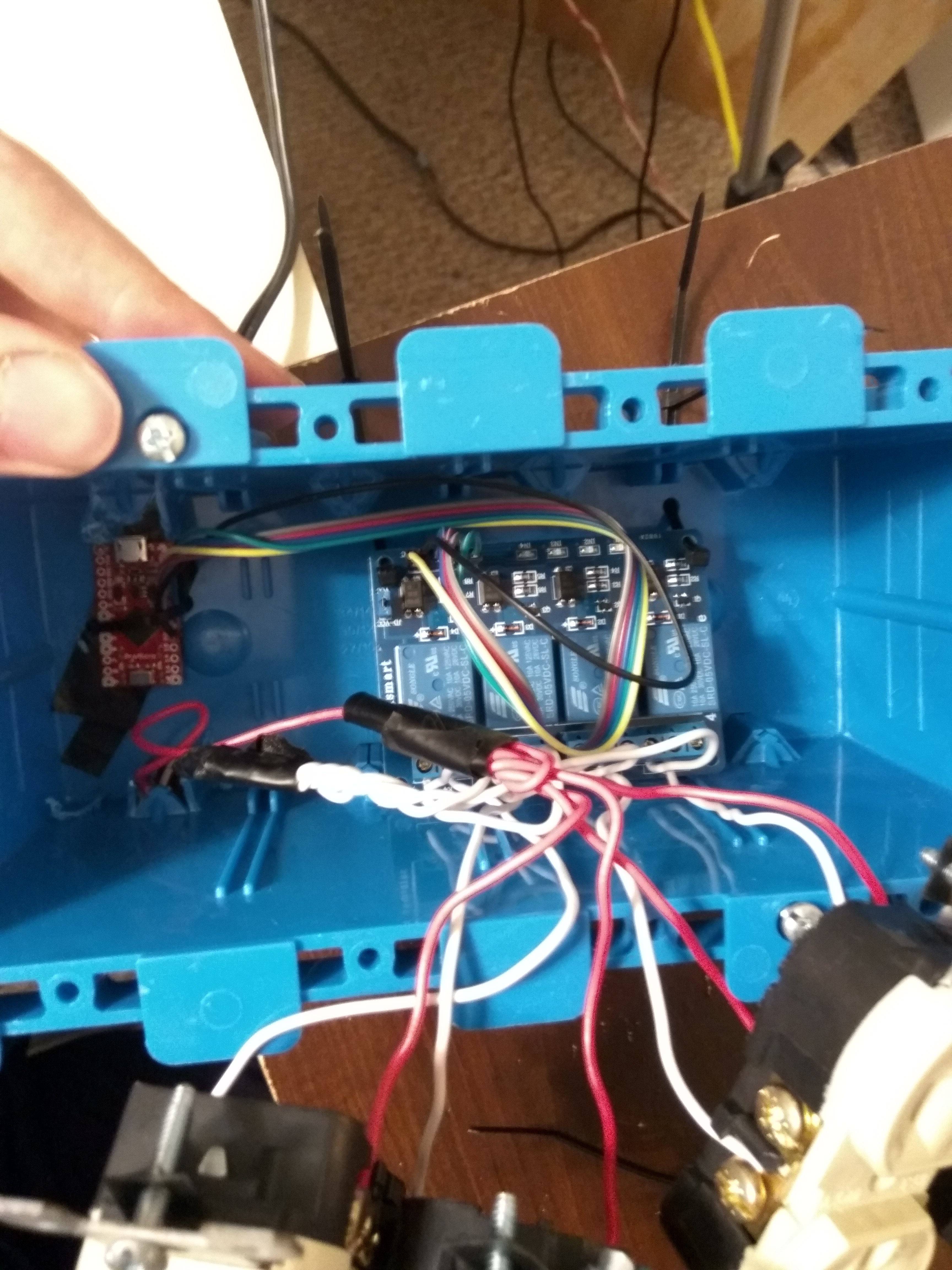
We will start by stripping five wires and soldering them to the board. One wire will go to the VCC slot and the other four will each be soldered to 18, 19, 20 and 21 pin slots. The opposite ends of the wires will hooked to the relay board matching the VCC to the microcontroller VCC wire and then from left to right 18, 19, 20 and 21 wires plugged into the remaining pins.
Drill and Trim Junction Box
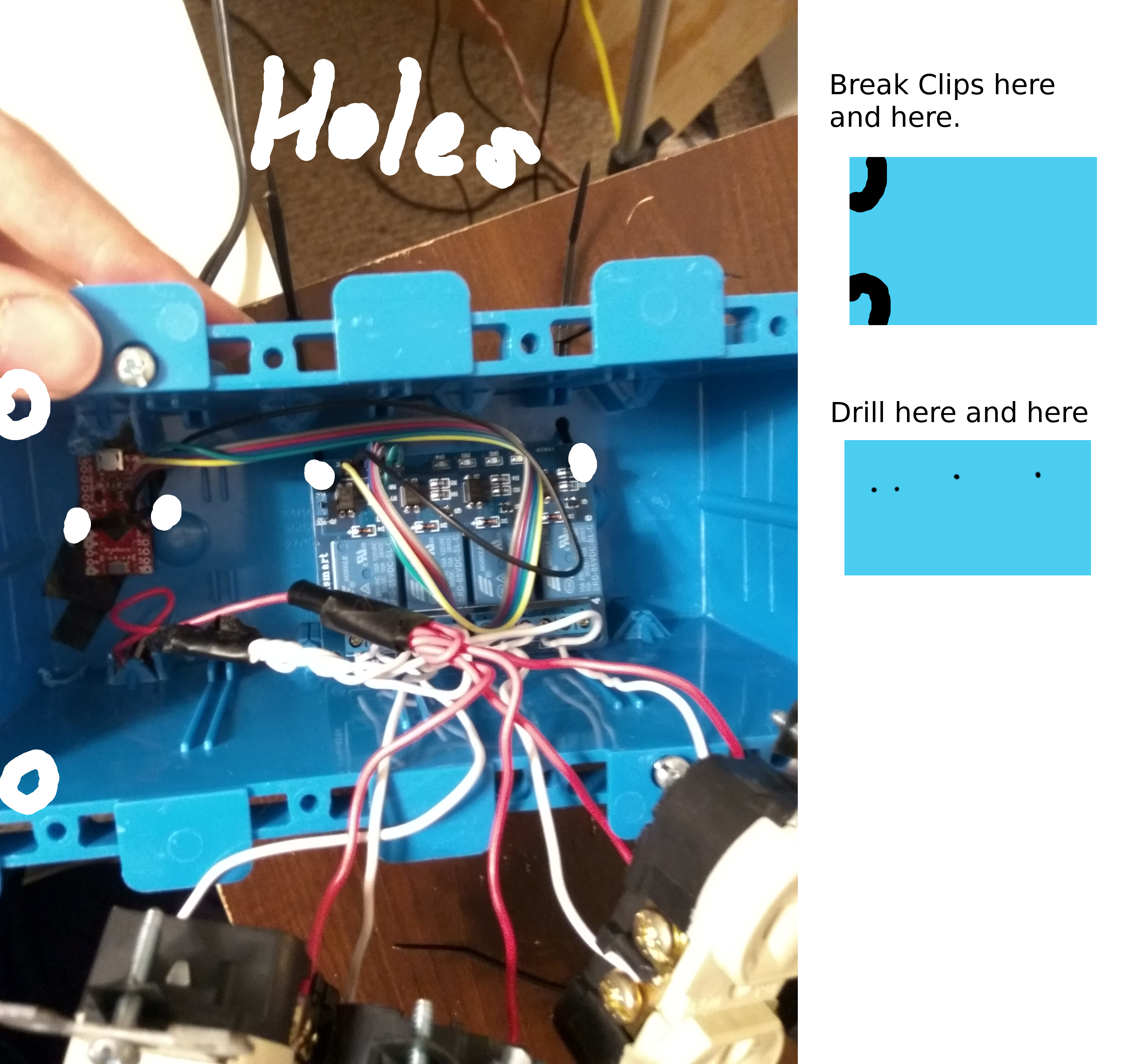
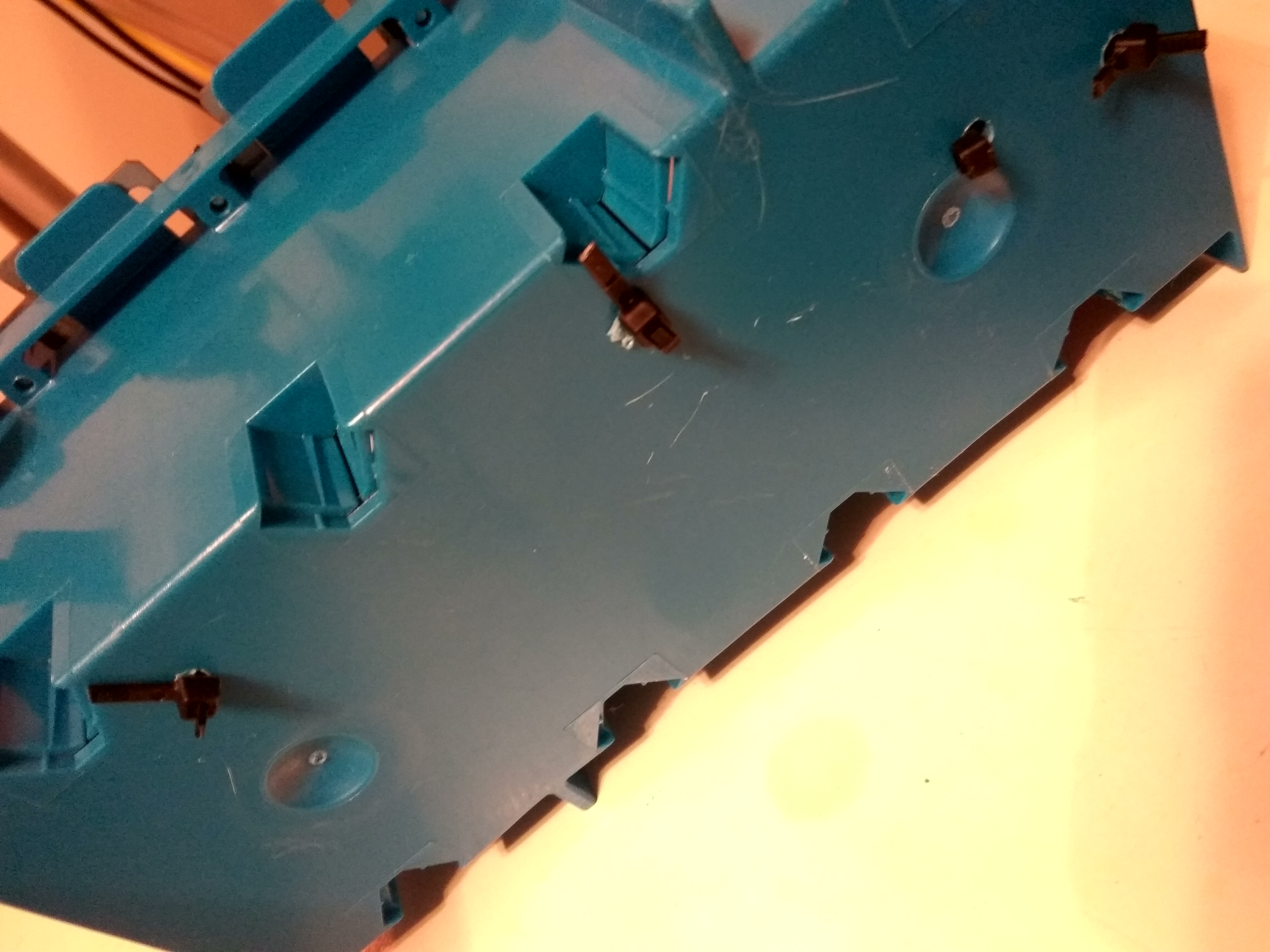
Next you are going to drill four holes in the back of the junction box; two for a zip tie across the microcontroller and two for zip ties that hold the relay board in place. I would just take a sharpie and mark the holes around the two boards to preference. (This is illustrated in the picture above.) You can then break off the wire escapes in the upper left and lower left. Power wires will go through one while the microcontroller will protrude out of the other.
Residential Wiring
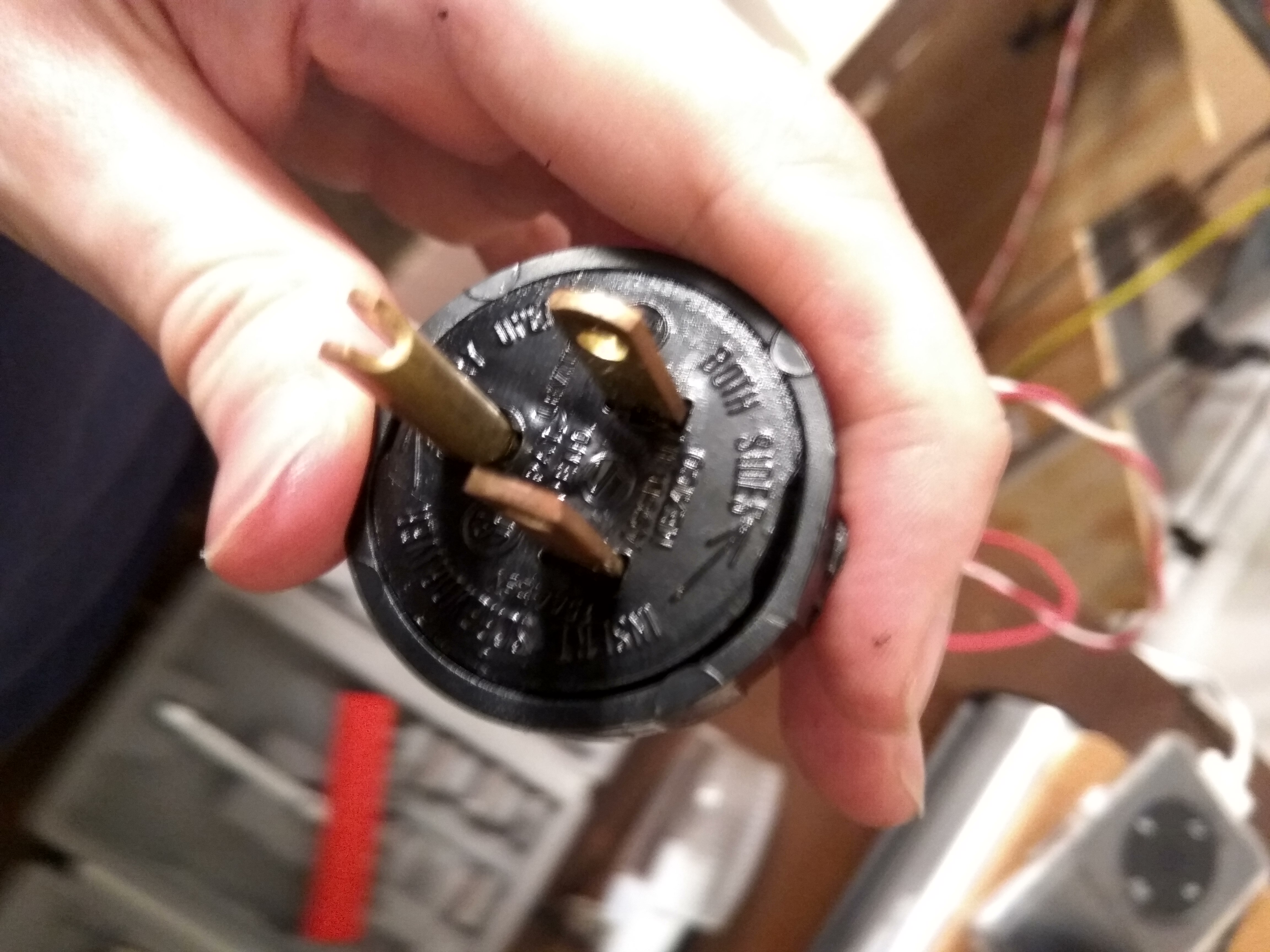
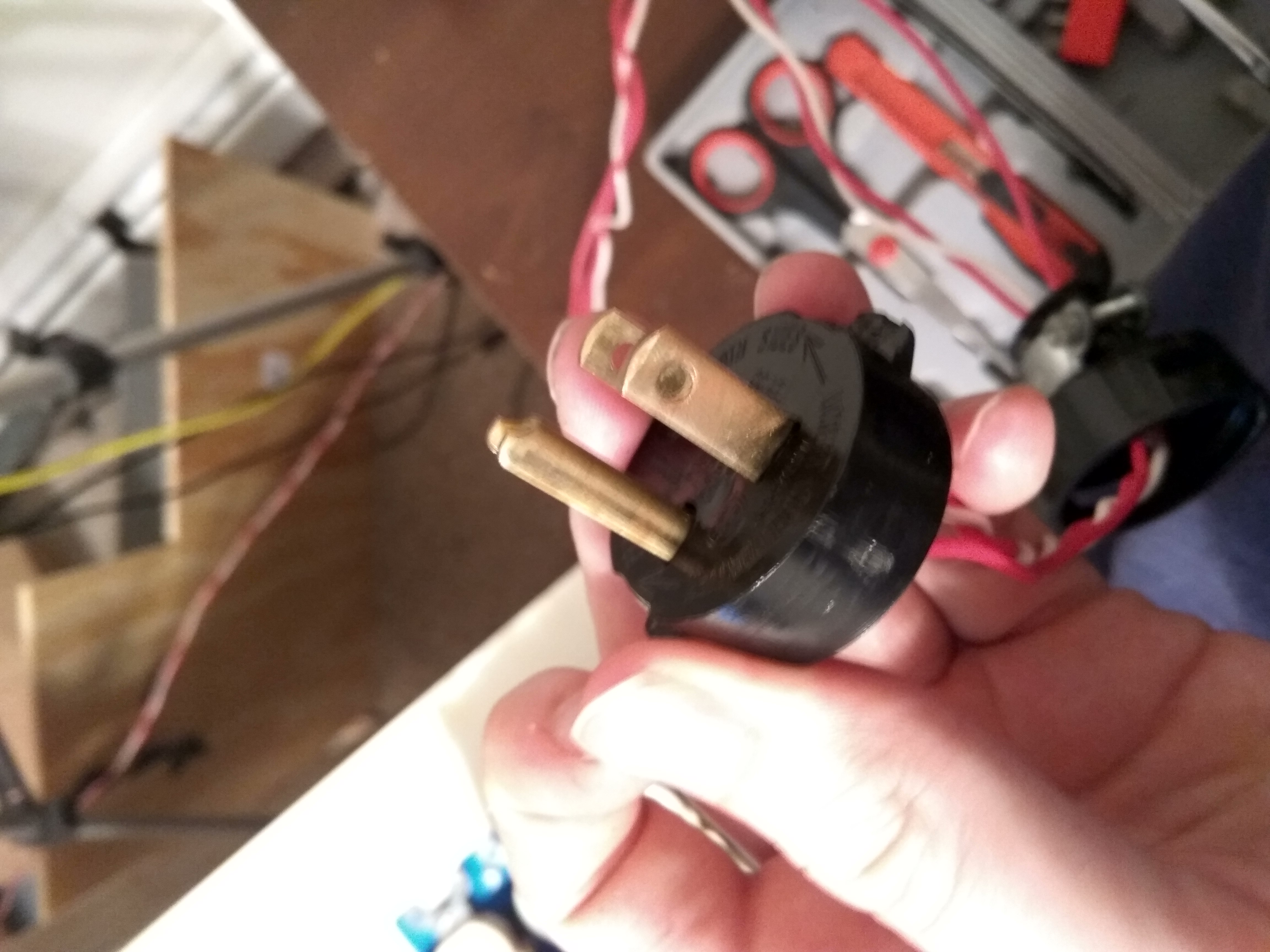
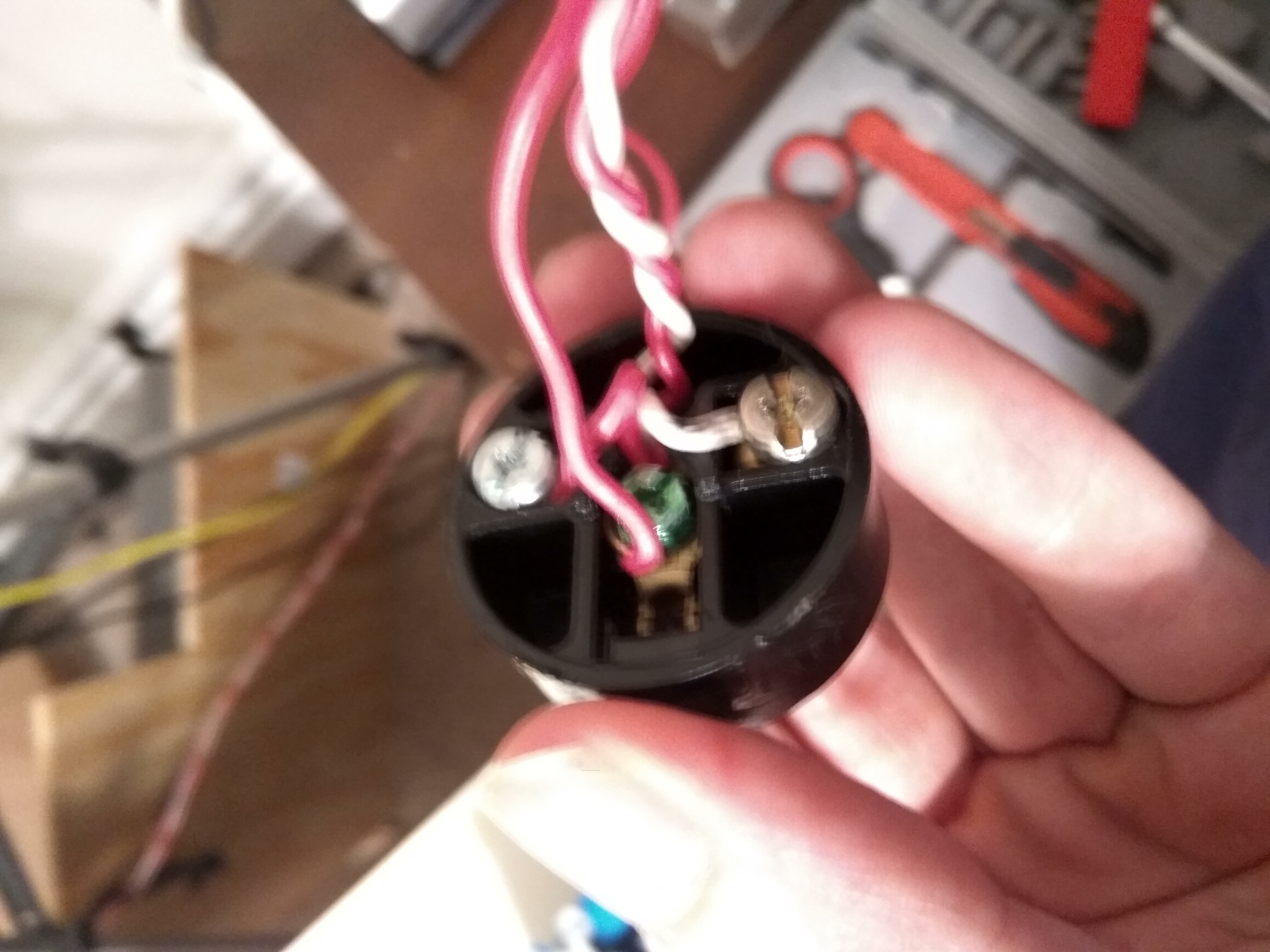
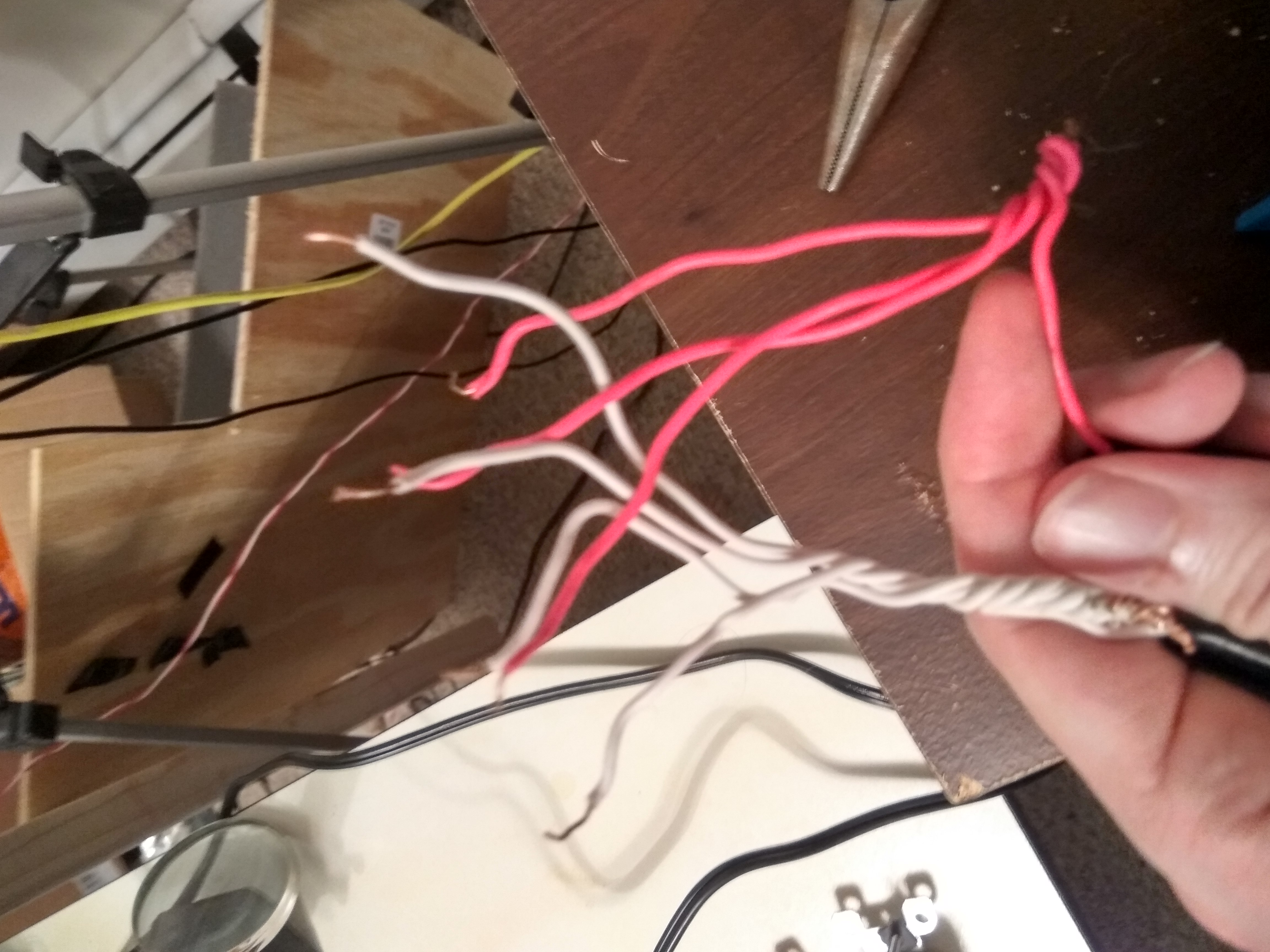
Measure the lengths of wire for bringing power to the outlet box, you will want anywhere from two to three feet and strip both ends. I had a spool of red and white 20 gauge wire laying around to use. Remove the head of the ‘male extension cord plug’, bend, hook and screw on a wire each of the terminals (positive and negative). Finally, replace rubber cap on male plug. (Sorry for blurry pictures on this one.)
Slip the other end of wires into one of the holes you made in the outlet box, bend them so that they will stay while we wire them up and you have about six inches of wire inside the box. Next cut and strip the ends of eight six inch wires; four of red and four of white. Twist the striped ends of the white wires to the white runner that comes into the box from the extension and the same for the red wires to the red runner. Finally cap both off with a wire connector nut.
Wiring Continued
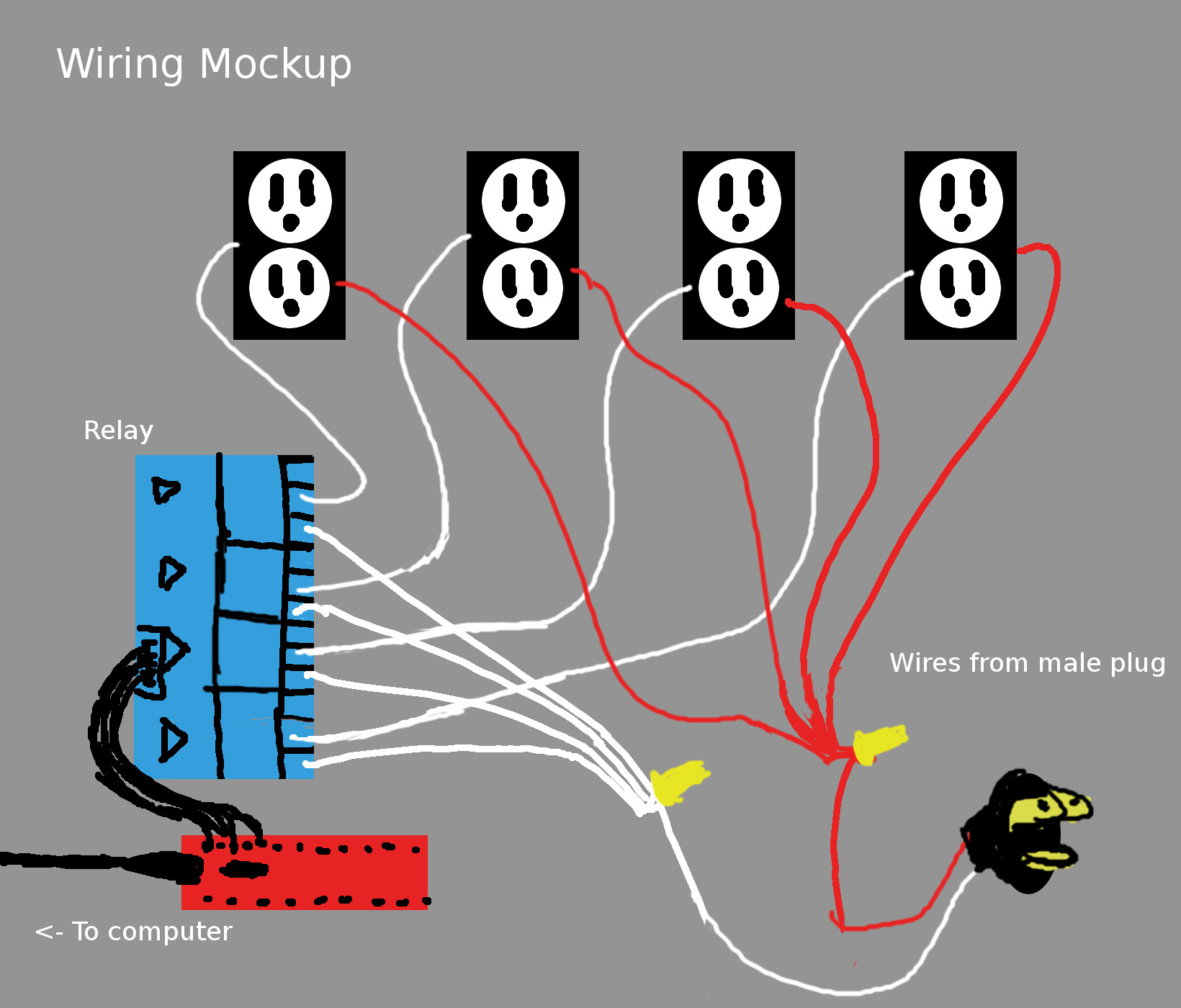
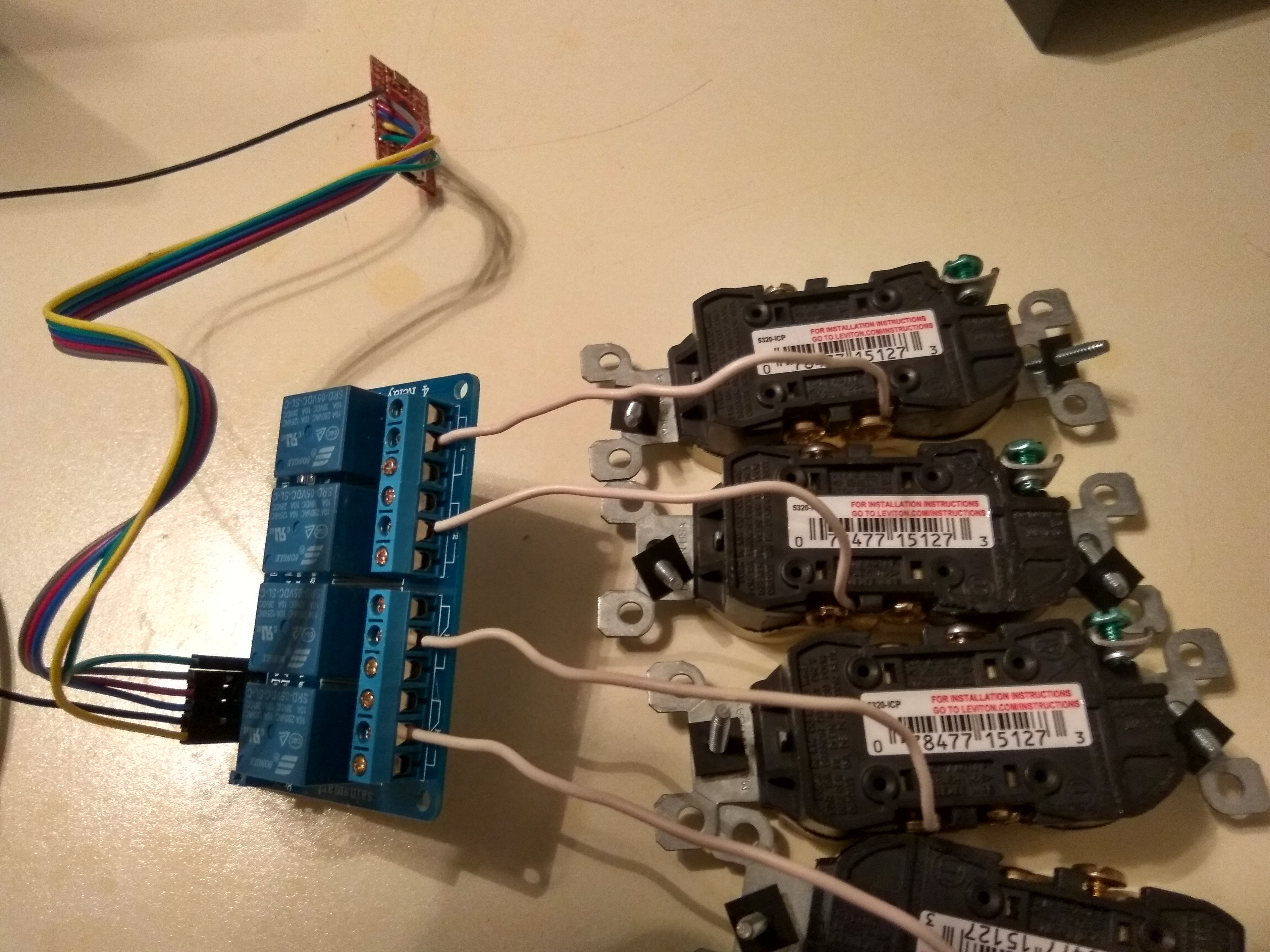
Unscrew the left and center fasteners of each relay, slip the ends of the white wires into each of the leftmost openings and tighten the screws. Check that they are snug with a gentle tug. Next cut and strip the ends of four more white wires. One end of each of these lead wires will go in the center fastener of a relay. (Just like described above with the white wires)
The other ends of these wires will be bent and screwed onto the brass side of their own receptacle. (Top or bottom should not matter.) Then you can bend and screw the ends of the red leads you made onto the silver screws of a receptacle. You have now created the circuit with the relay acting as an electronically controlled switch, please examine the diagram below and double check your work.
Upload Microcontroller Test
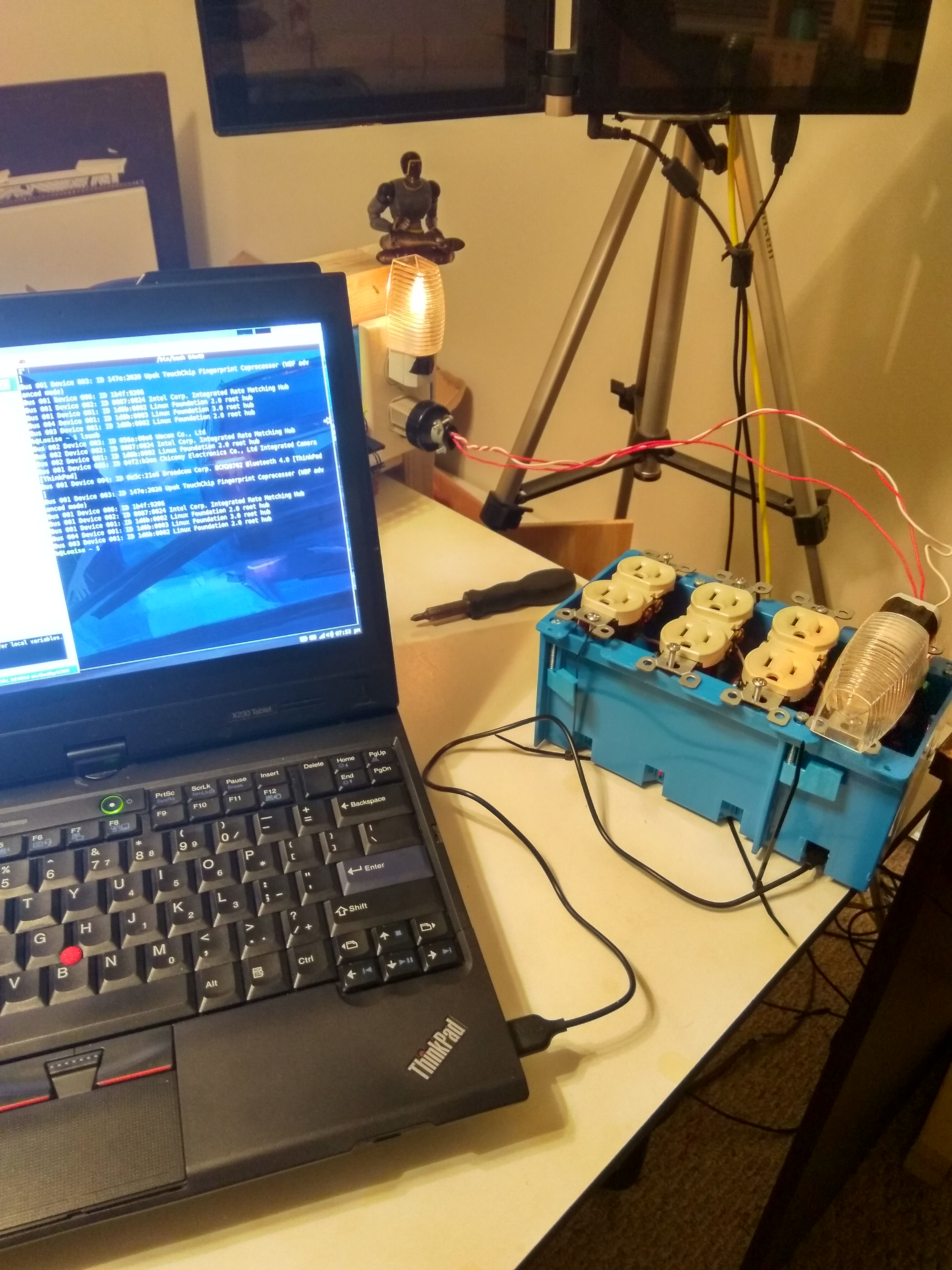
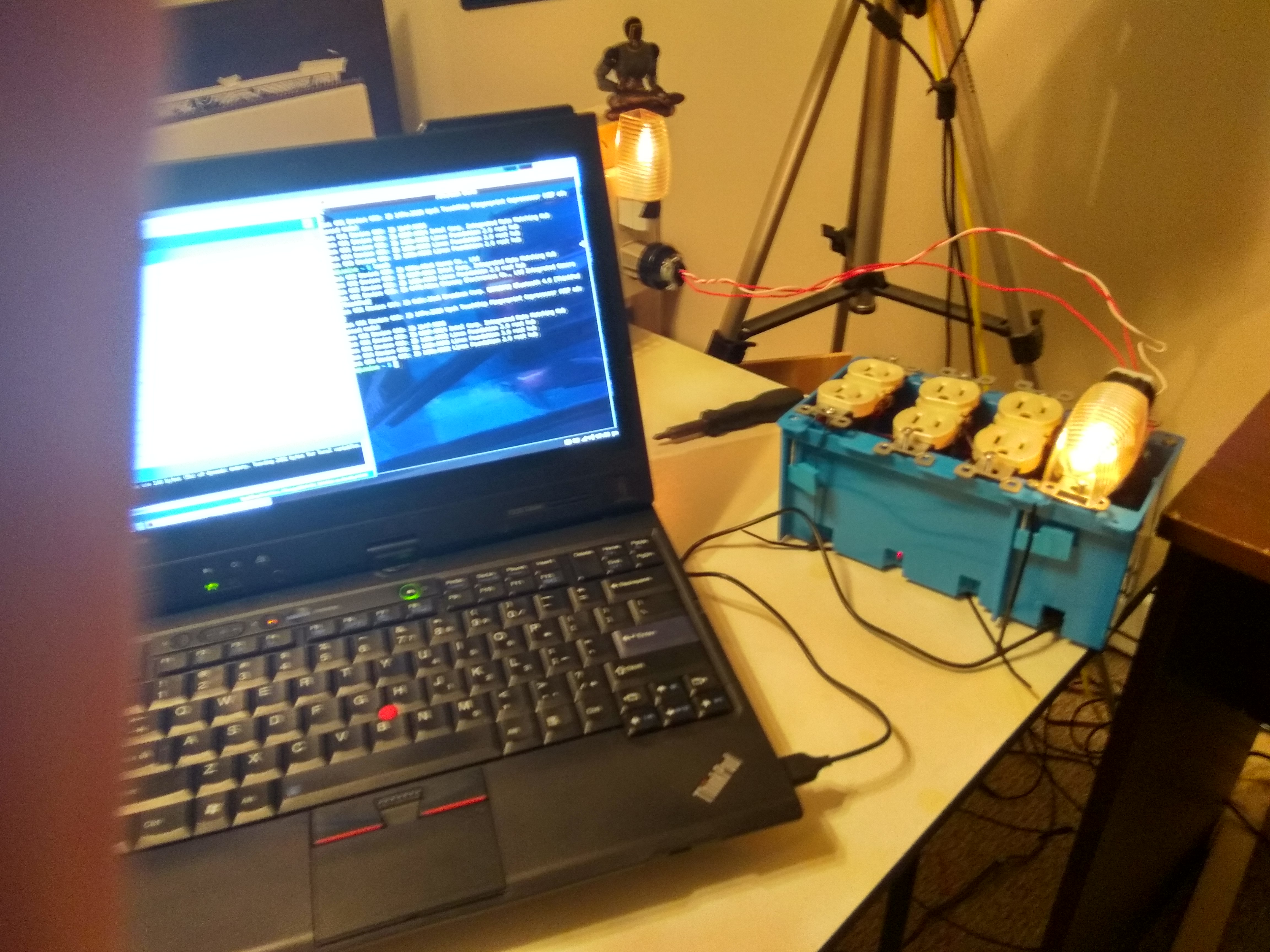
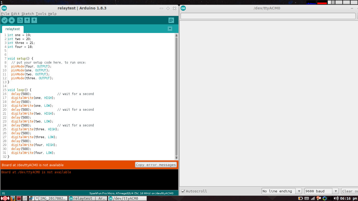
Plug your microcontroller into your PC, setup your Arduino environment and upload this ‘relay test’ program. You should see the relays start flipping immediately once you upload it. Your next job is to make sure that the relays light up in order from left to right. You can edit the global pin numbers in the script. (Note: if you are using another type of board you will probably need to figure out what pins you are using and make the the four globally defined pins and retry this program.)
CODE: https://gist.github.com/malceore/9eab4f4be6a305efa2463a2533ca4d75
Upload Microcontroller Program
Once you have the pins flipping in the right order you can replace the global pins in the serial-r-w-program below with the ones you have working from the relay test program and upload this serial-r-w-program to your microcontroller. You will no longer see the relays lighting up in any order but instead constant. If you go to Arduino options you can open your ‘serial monitor’ and try typing in the simple API commands.
EX: one:on
EX: one:off
EX: two:on
EX: two:off
...
If you have reproduced correctly you should see and hear the relays turn on and off.
CODE: https://gist.github.com/malceore/7dcfd1381bcf97c113e200be6859f694
Assembly and Test
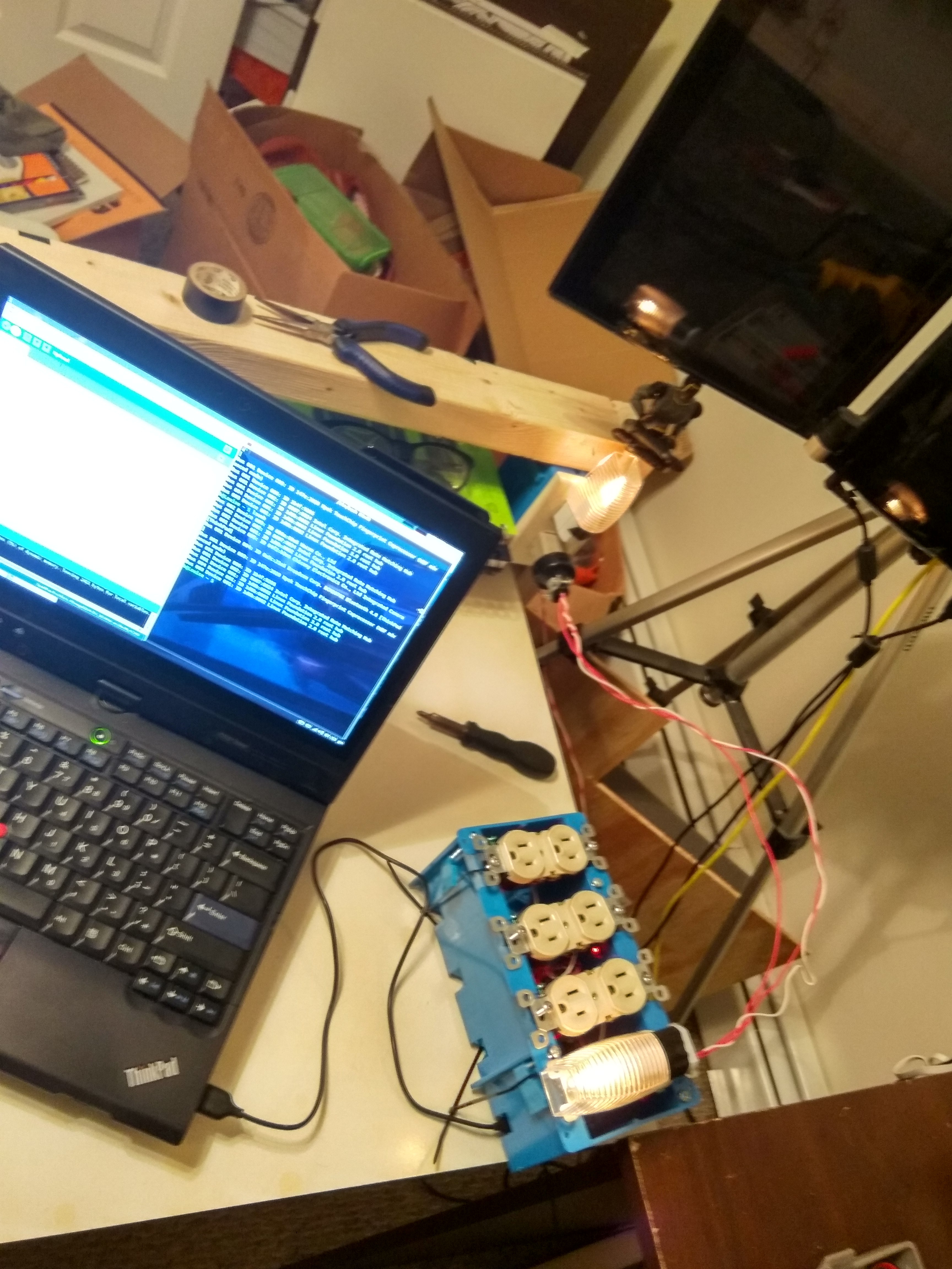
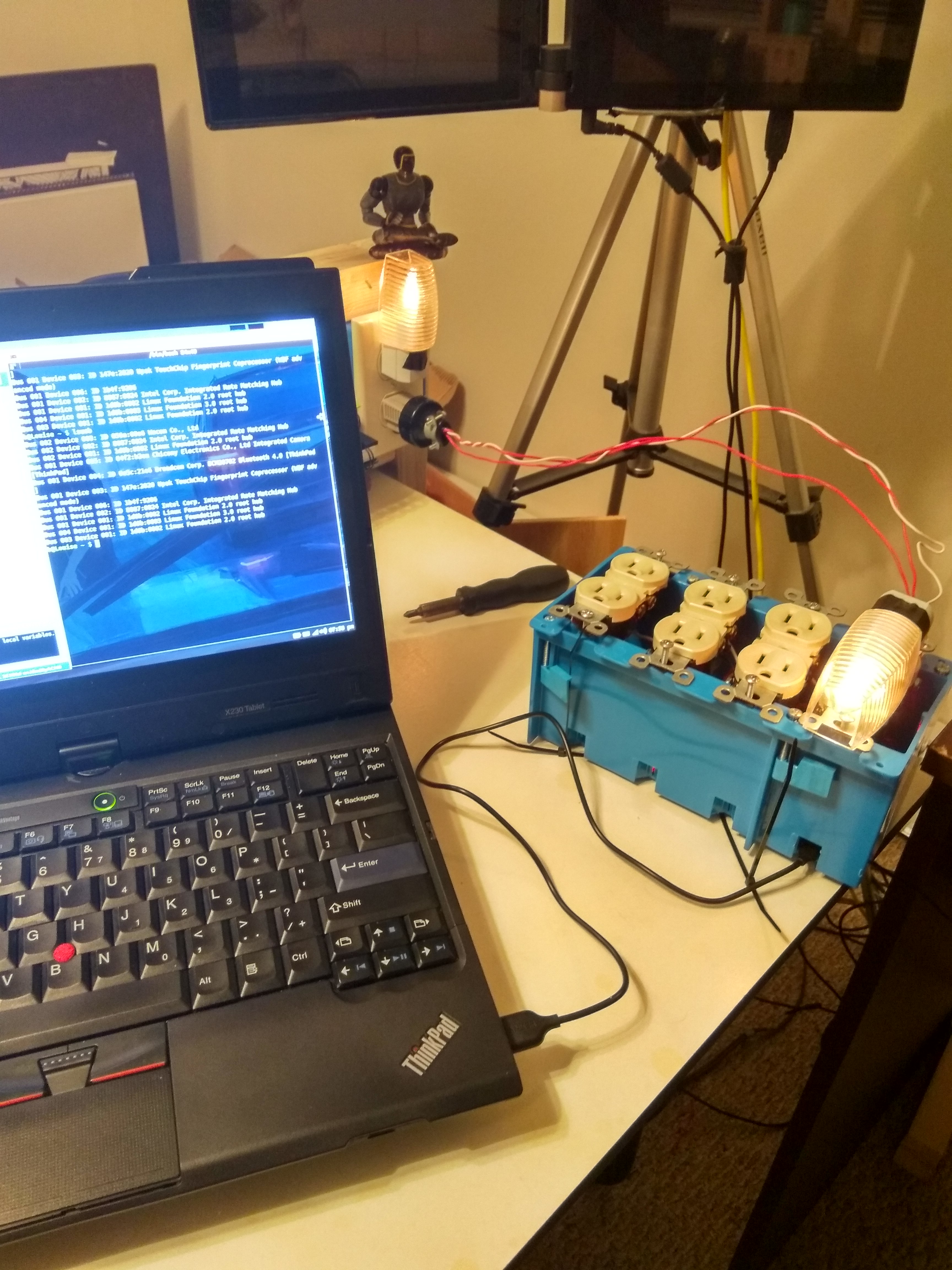
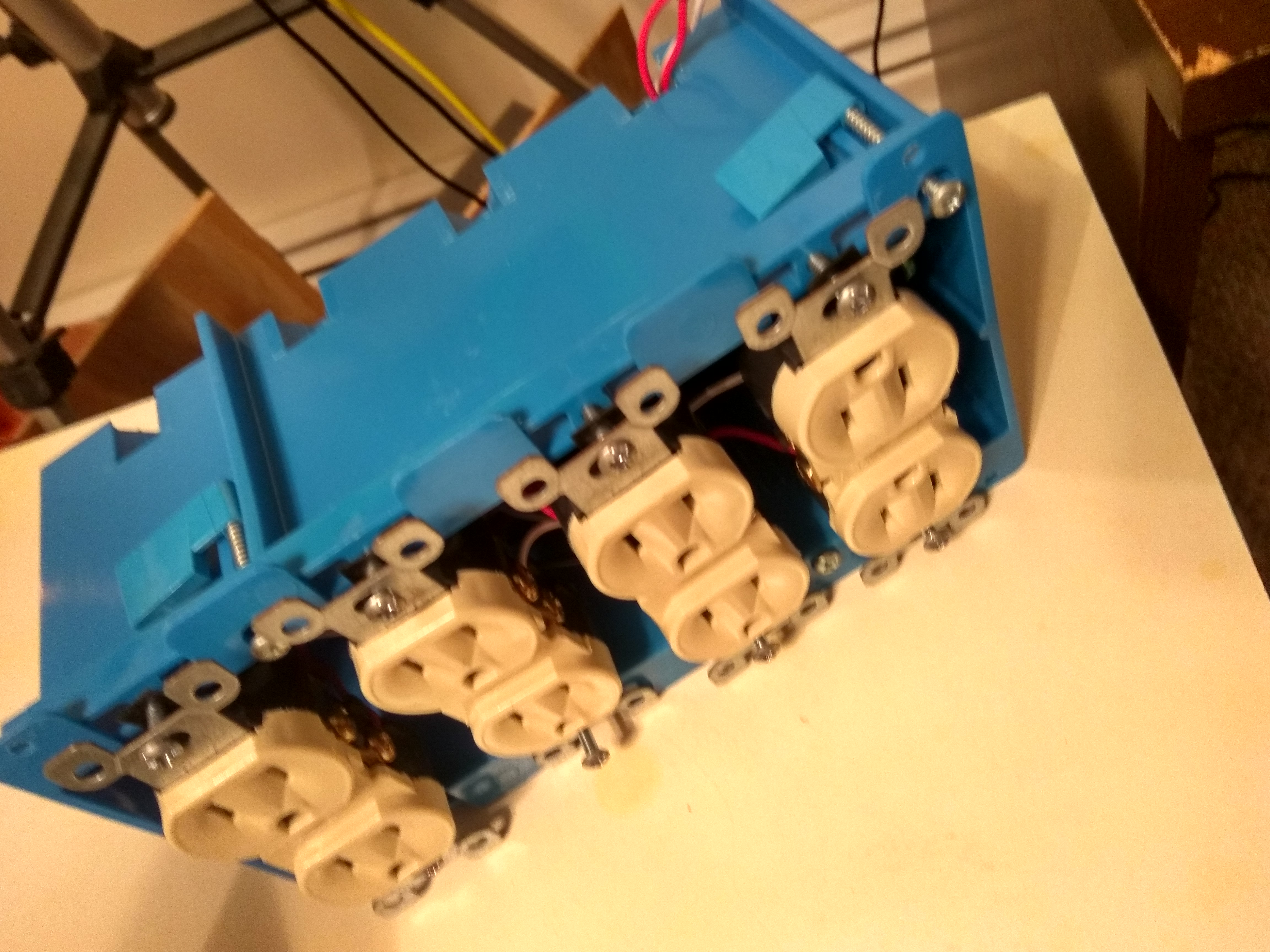
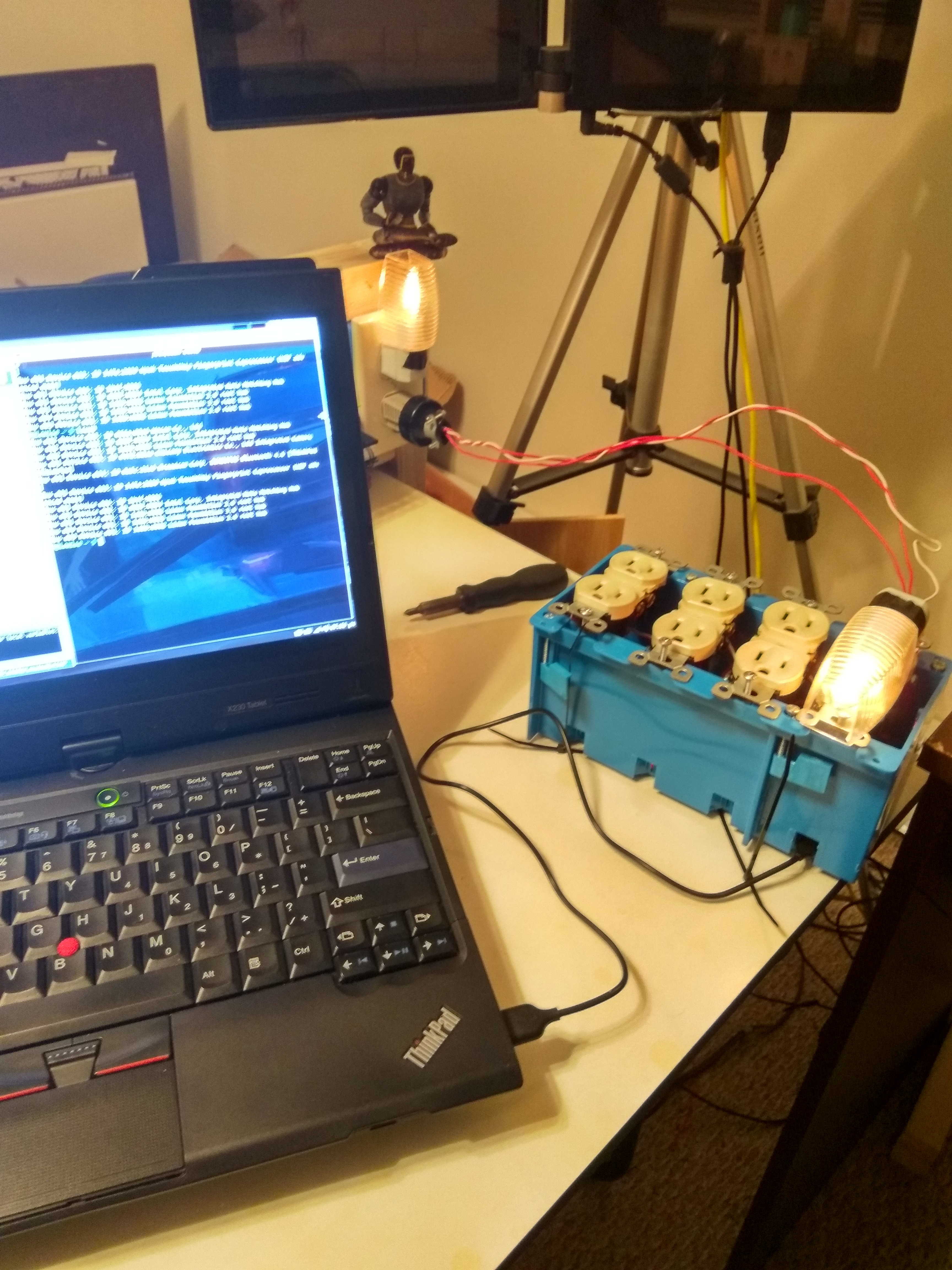
If the above serial program works than we can proceed with assembly and further tests using outlets and some test lights. Start by loosely zip tying your relay board and microcontroller to the back of the box. Make sure that you can access your microcontroller’s microusb post from the second wire-box hole.(See pictures if this is not clear.)
Next you can fold excess wire into the back-top of the outlet box, use electrical tape to hold wires out of the way and loosely screw in receptacles.
When everything is secure you can try plugging in your male extension cord into an outlet and some test lights into your box’s receptacles. You should be able to turn them on and off using the serial API commands from the previous statement. If you are not able to please repeat processes from step five on and try again.
Configuring Python Server
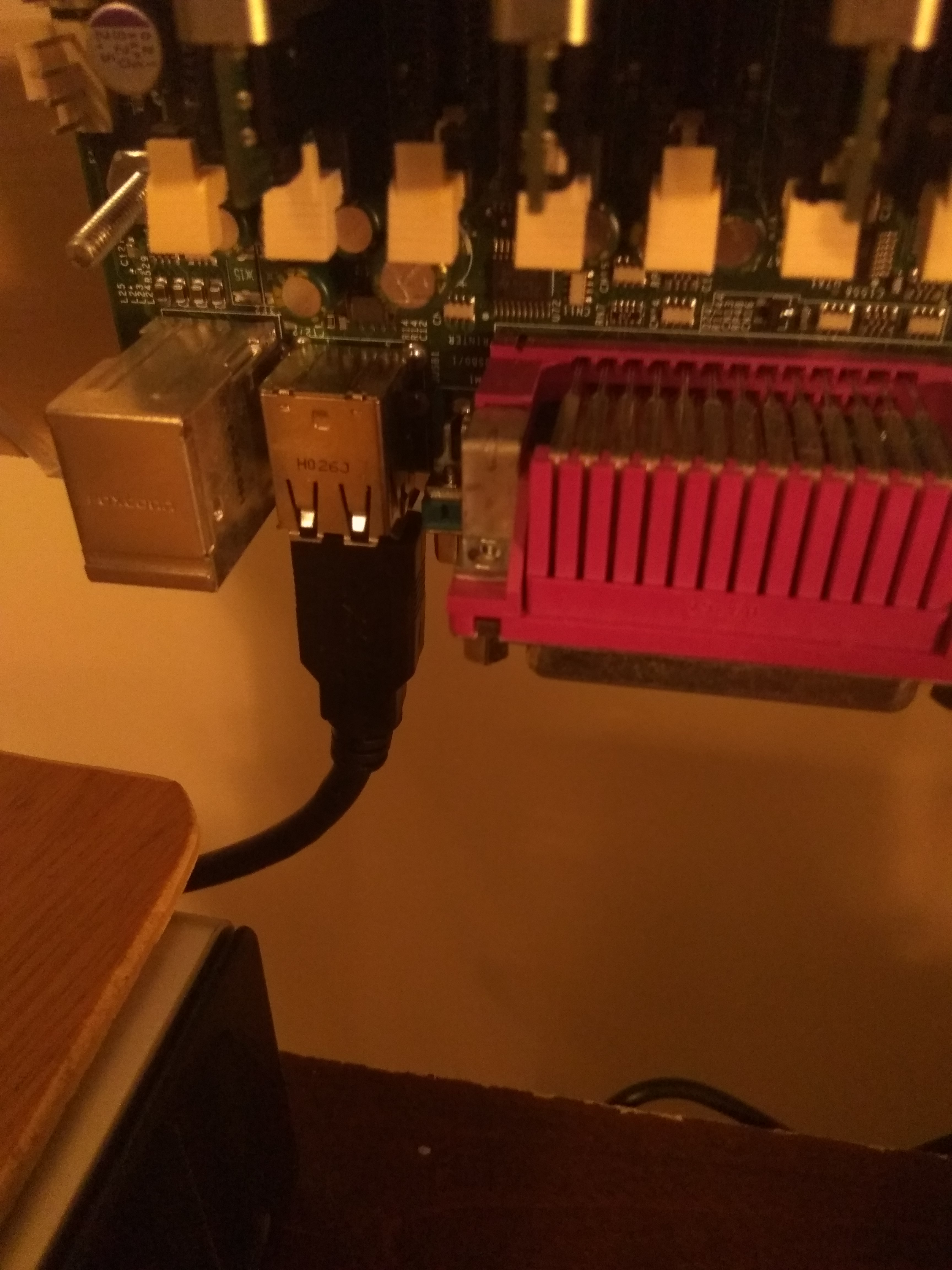
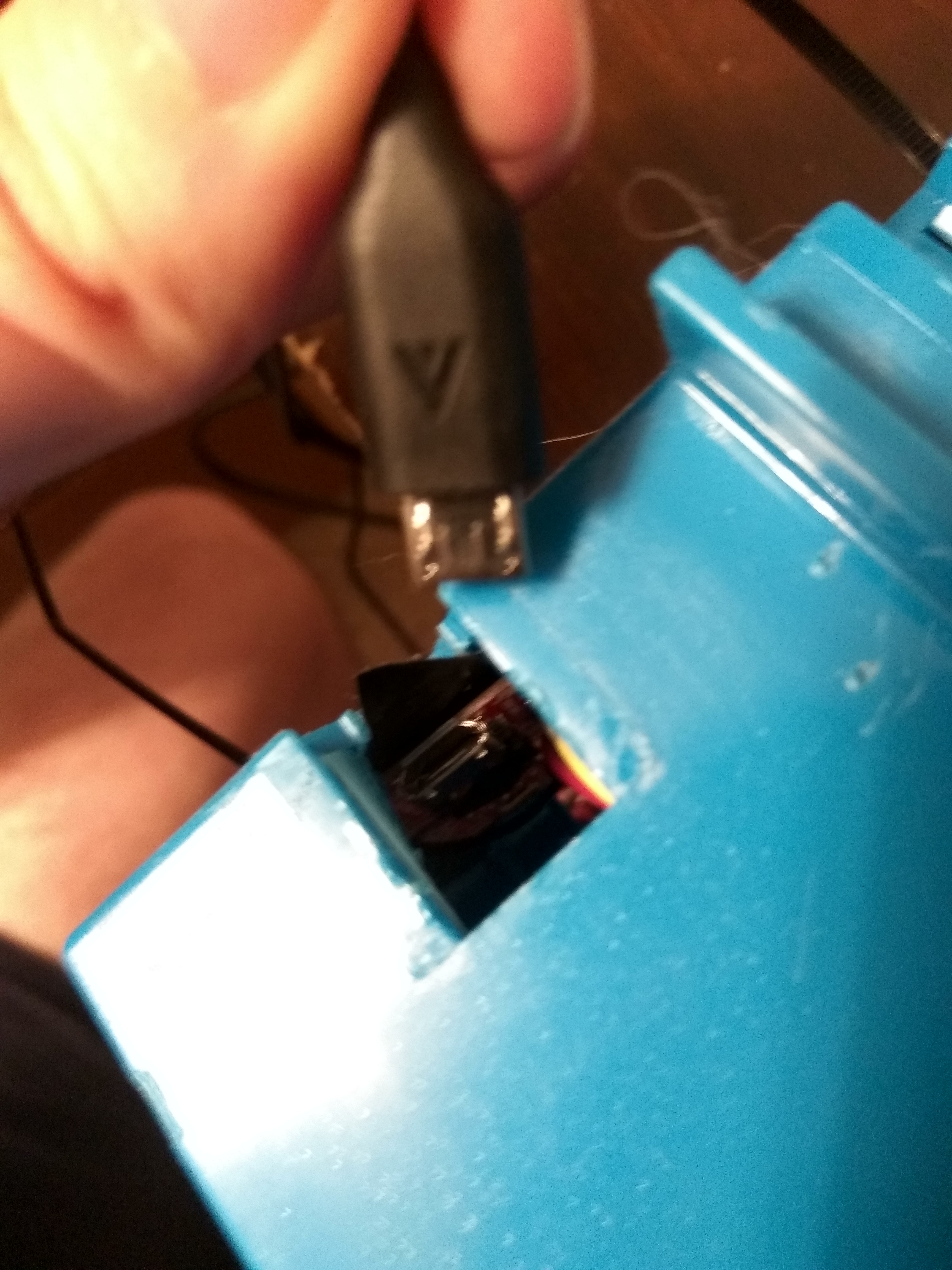
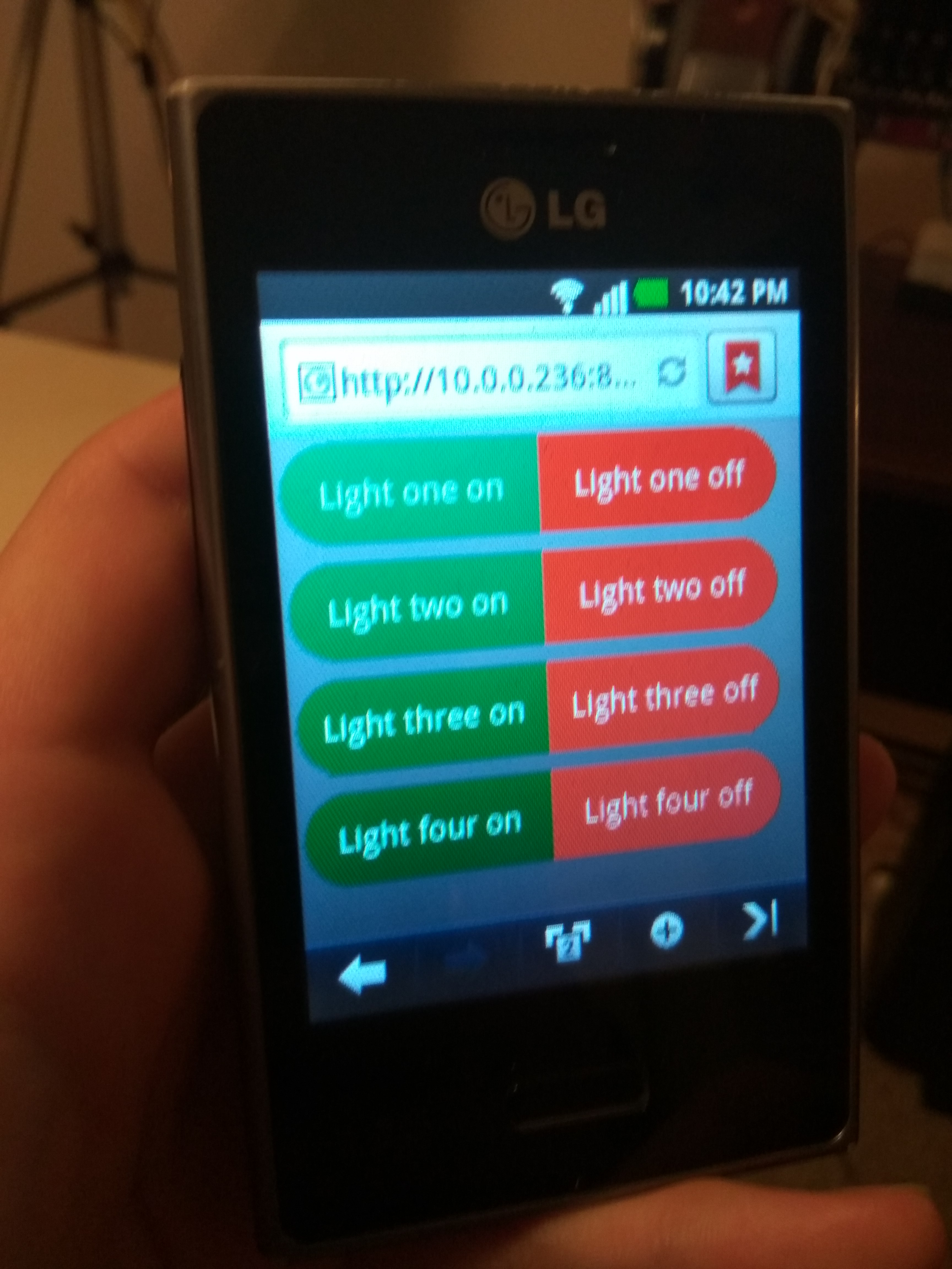
Next we connect the usb end of the microusb into your server and confirm that it can see it using lsusb. (I actually do this on a Ubuntu virtual machine which takes a little more configuration. Additionally If you don’t have a server you can always source one from an old laptop which are fairly power efficient to leave always-on.) Next you will need to install some packages;
sudo apt-get update
sudo apt-get install python python-serial python-urlparse python-twisted
Next you need to create a file called ‘server.py’ and copy the below script into it. You may need to replace ‘/dev/ttyACM0’ with whatever your device is registered as on your system. But for most this should suffice. Also if you run into ‘device is busy’ error you will need to blacklist that usb from modprobe.
Next you need to create a file called ‘server.py’ and copy the below script into it. You may need to replace ‘/dev/ttyACM0’ with whatever your device is registered as on your system. But for most this should suffice. Also if you run into ‘device is busy’ error you will need to blacklist 'ttyACM0' on modprobe.
sudo python server.py
What this program does is host a webserver using Python’s Twisted library and based on some restful API will write to the serial port of the microcontroller the exact same way you did earlier with the ‘serial monitor’. You can go to the server via a web browser by typing in the IP of your server(ifconfig command from the linux server’s CLI), port 8080 and /index.html.
EX: 10.0.0.10:8080/index.html EX: 192.168.0.13:8080/index.html
CODE: https://gist.github.com/malceore/3dd520347bd108eb82e1f02dfbeeca5f
Finalization and Future Plans
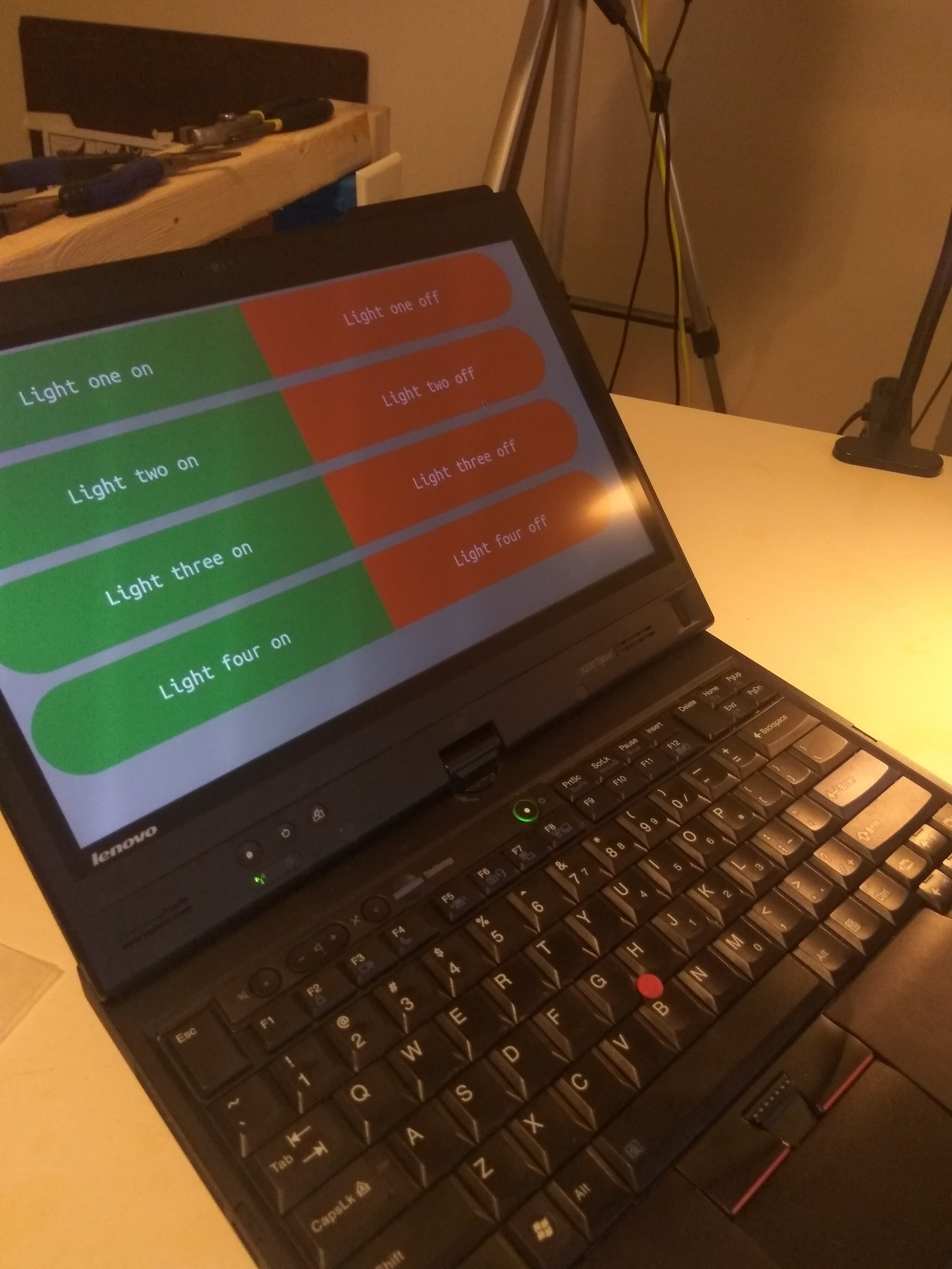
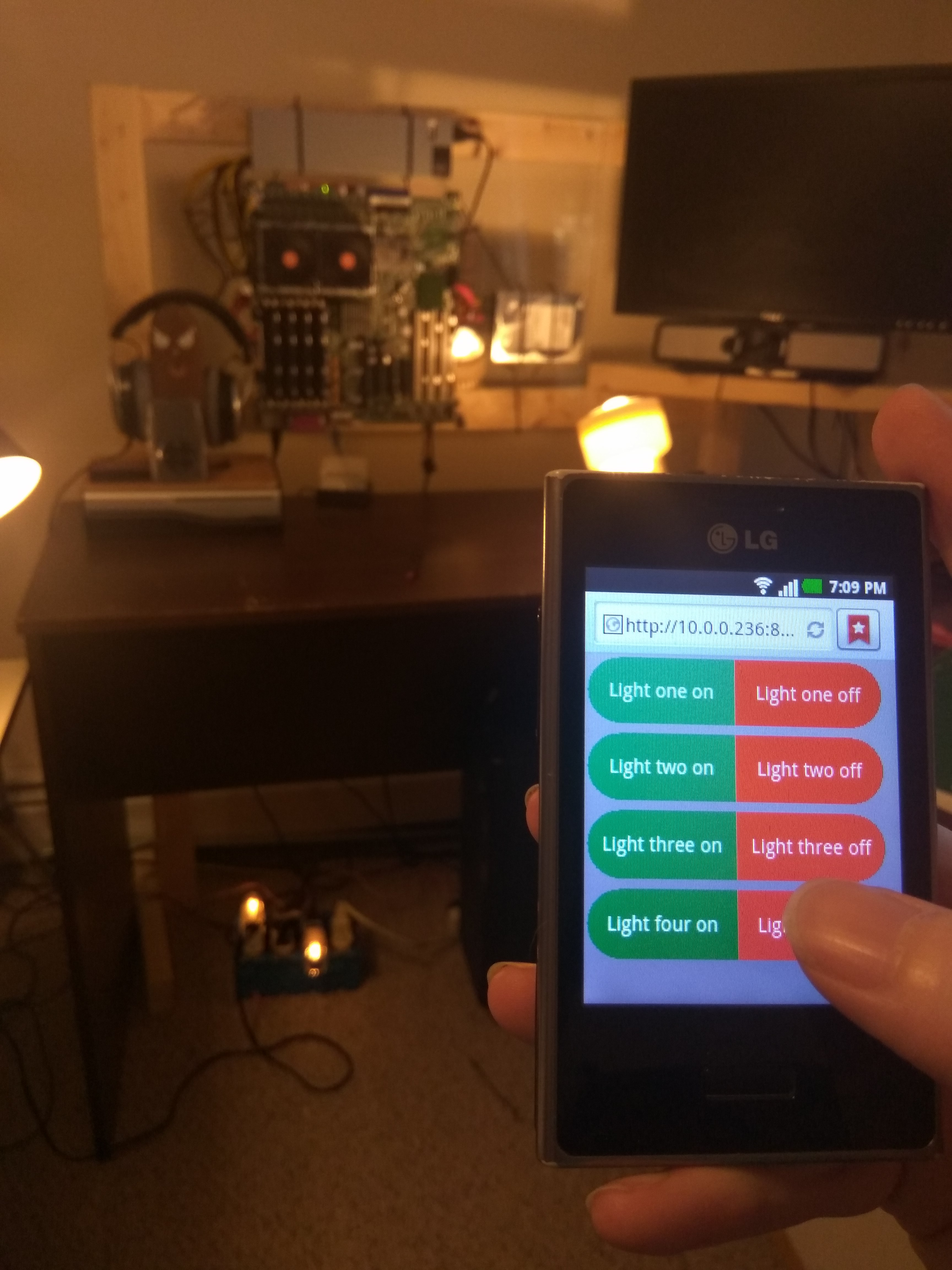
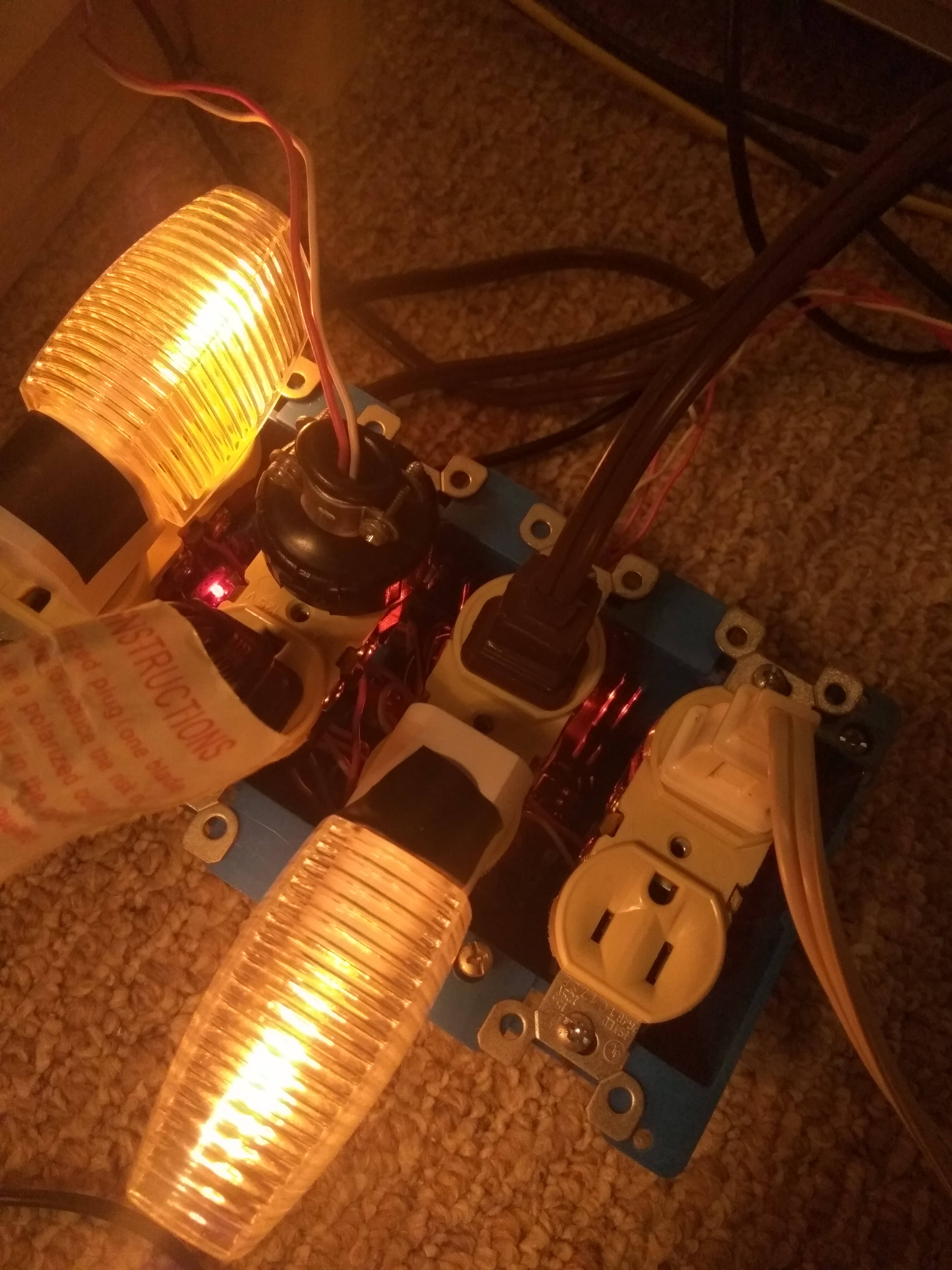
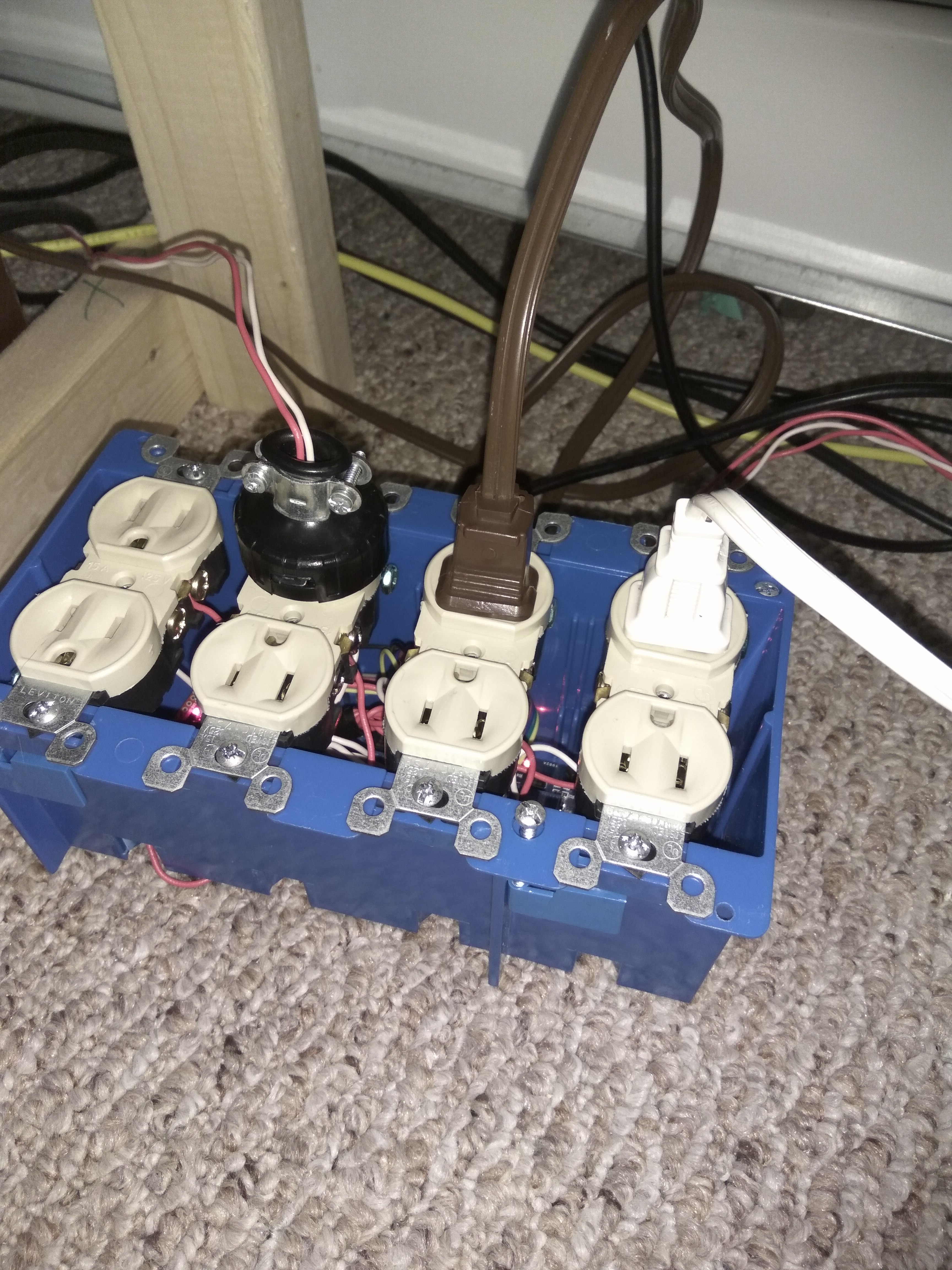
From the web-app you can tap the buttons and they should toggle on and off the relays and thus whatever is plugged into their corresponding receptacles. You can tighten up the zip ties and screw down all the screws now. You now have application controlled lights, congratulations!
In the future I am going to work voice controlled properties to this application, so that you can have always listening or press button commands controlled from the web-app.
A note on security, this web app is still experimental and most likely open to injection. If anyone wants to suggest a fix I will credit them, but for now I would not expose that port to the internet.