Web Controlled Desk Lamp With XIAO ESP32 C3
by Arnov Sharma in Circuits > LEDs
3009 Views, 9 Favorites, 0 Comments
Web Controlled Desk Lamp With XIAO ESP32 C3
.gif)
.gif)
.gif)

Greetings,
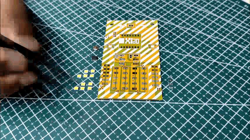
So this is the WEB Desk Lamp made from PCBs, a unique and innovative DIY project that combines electronics and home automation.
The lamp can be controlled remotely through a web server, allowing users to turn it on and off using a smartphone or computer.
The lamp is built with printed circuit boards (PCBs), which provide a strong and compact framework for the electronic components.
It operates on Seeed's XIAO ESP32 C3 DEV Board, which controls a mosfet that drives ten 0.5W LEDs.
This project is a great way to learn about electronics, programming, and home automation.
This Instructables will explain how this project was made and how you can create it in a few simple steps, so let's get started.
Supplies
These were the things used in this built-
- Custom PCBs
- Seeed XIAO ESP32 C3
- 3V 0.5W LEDs
- AO4406 Mosfet IC
- 10K Resistor
- Header Pins
- 3D Printed Parts
3D DESIGN

The design was first modeled in Fusion360, where we modeled a single board with dimensions of 90 mm x 50 mm and then copied it several times to arrange all of the boards into the shape of a desk lamp.
Each PCB has four mounting holes near its vertices; we use circuit supporting parts to join two PCBs together with these holes.
After completing the design, the circuit's DWG file was exported in order to model the PCB in cad software.
All of the circuit support components were exported as mesh files for 3D printing.
To 3D print all of the components, we used transparent PLA with a 0.6mm nozzle.
PCB DESIGN


The PCB Design process begins with creating the schematic, which in this case consists of 20 LEDs, 10 of which are connected in parallel with one Mosfet as a switch setup controlled by the XIAO MCU.
Here, we use two Mosfets as switches to control two different color LEDs, one white and one warm white. (this was the idea but later this plan was changed so just one color was used)
Two more buttons were also added, but they will be optional because they may not be used in the main sketch.
We model the PCB with Fusion360's provided Cad files, using the DWG file as the PCB outline.
Seeed Fusion PCB Service
.gif)
.gif)

As for both of the PCBs in this Web Desk LED, they were sent to SEEED Studio for samples.
An order was placed for a yellow solder mask with white silkscreen for LED boards, a black solder mask with white silkscreen for the base PCB.
PCBs arrived in less than a week, which was super fast.
The quality was very good considering the price, which was also pretty low.
The PCB quality of both PCBs was just awesome!
Seeed Fusion PCB Service offers one-stop prototyping for PCB manufacture and PCB assembly, and as a result, they produce superior quality PCBs and Fast Turnkey PCBA within 7 working days.
Seeed Studio Fusion PCB Assembly Service takes care of the entire fabrication process, from PCB manufacturing and parts sourcing to assembly and testing services, so you can be sure they are getting a quality product.
After gauging market interest and verifying a working prototype, Seeed Propagate Service can help you bring the product to market with professional guidance and a strong network of connections.
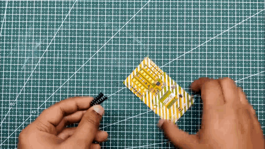
Next, we prepare for the PCB assembly process.
PCB Assembly
.gif)
.gif)
.gif)
.gif)
.gif)
- We start first with the solder paste dispensing process by adding solder paste to each component pads one by one.
- We then used an ESD tweezer to carefully pick and place all the SMD LEDs and components in their assigned places one by one.
- After the "pick and place process, " we carefully lifted the whole circuit board and placed it on the Reflow hotplate.
- Next, we place the header pin in the XIAO Pads and solder it with help of a soldering iron.
- At last, we place XIAO in its place and the LED Board Assembly is completed.
Power Board Assembly
.gif)
Assembly of the power board or base board is simple; we simply solder a USB Micro THT Port and a DIP ON/OFF Switch to their pads with a regular soldering iron.
For powering the LAMP, a USB cable will be connected to this board.
Test Sketch- BLINK and FADE
.gif)
.gif)
Before final assembly, we test a few sketches to see if the LED setup is working properly.
We first upload the blink sketch to the XIAO Board, and in the blink sketch, we replace the built-in LED Builtin with 2, which is the GPIO number of the XIAO's D0 pin, which is connected to the mosfet gate.
void setup() {
  // initialize digital pin LED_BUILTIN as an output.
  pinMode(2, OUTPUT);
}

// the loop function runs over and over again forever
void loop() {
  digitalWrite(2, HIGH);   // turn the LED on (HIGH is the voltage level)
  delay(1000);                       // wait for a second
  digitalWrite(2, LOW);    // turn the LED off by making the voltage LOW
  delay(1000);                       // wait for a second
}
Next, we open the fade sketch, change its pin number to 2, and upload it to the Xiao to see the fade effect of the LED, which was also working.
int led = 2;           // the PWM pin the LED is attached to
int brightness = 0;    // how bright the LED is
int fadeAmount = 5;    // how many points to fade the LED by

// the setup routine runs once when you press reset:
void setup() {
  // declare pin 9 to be an output:
  pinMode(led, OUTPUT);
}

// the loop routine runs over and over again forever:
void loop() {
  // set the brightness of pin 9:
  analogWrite(led, brightness);

  // change the brightness for next time through the loop:
  brightness = brightness + fadeAmount;

  // reverse the direction of the fading at the ends of the fade:
  if (brightness <= 0 || brightness >= 255) {
    fadeAmount = -fadeAmount;
  }
  // wait for 30 milliseconds to see the dimming effect
  delay(30);
}
Result So Far
.gif)
So far, we have a working LED board that is controlled by an XIAO Dev board and driven by a Mosfet as a switch configuration. We can even add 10 more LEDs to the PCB's empty slots, which will be controlled by a different Mosfet setup. The original plan was to fill the empty space with warm white LEDs.
Because this board is functional overall, the main sketch can now be added to the XIAO and tested one more time before beginning the main assembly process.
Web Desk LED Lamp Sketch
.gif)
Here's the main sketch for this project, a web server sketch that I modified from my previous Home Automation project; even the web page title is from that project, and it's easily changed by changing the lines below.
client.println("<body><h1>HOME AUTOMATION DUAL OUTPUT</h1>");
- Copy this sketch and change the SSID and password before uploading it to the XIAO DEV Board; this setup will also work with any ESP32 or ESP8266 boards.
- After uploading the sketch, we open the serial monitor and allow the ESP to connect to the local WIFI. Once connected, you will see its IP address in the serial monitor.
- Copy the IP Address and open it into any browser which will let you access the Web page for controlling the LED LAMP.
#include <WiFi.h>

// Replace with your network credentials
const char *ssid = "Your SSID";
const char *password = "Your PASS";

// Set web server port number to 80
WiFiServer server(80);

// Variable to store the HTTP request
String header;

// Auxiliar variables to store the current output state
String output1State = "off";


// Assign output variables to GPIO pins
const int output1 = 2;

void setup() {
  Serial.begin(115200);
  // Initialize the output variables as outputs
  pinMode(output1, OUTPUT);
  digitalWrite(output1, LOW);

  // Connect to Wi-Fi network with SSID and password
  Serial.print("Connecting to ");
  Serial.println(ssid);
  WiFi.begin(ssid, password);
  while (WiFi.status() != WL_CONNECTED) {
    delay(500);
    Serial.print(".");
  }
  // Print local IP address and start web server
  Serial.println("");
  Serial.println("WiFi connected.");
  Serial.println("IP address: ");
  Serial.println(WiFi.localIP());
  server.begin();
}

void loop(){
  WiFiClient client = server.available();   // Listen for incoming clients

  if (client) {                             // If a new client connects,
    Serial.println("New Client.");          // print a message out in the serial port
    String currentLine = "";                // make a String to hold incoming data from the client
    while (client.connected()) {            // loop while the client's connected
      if (client.available()) {             // if there's bytes to read from the client,
        char c = client.read();             // read a byte, then
        Serial.write(c);                    // print it out the serial monitor
        header += c;
        if (c == '\n') {                    // if the byte is a newline character
          // if the current line is blank, you got two newline characters in a row.
          // that's the end of the client HTTP request, so send a response:
          if (currentLine.length() == 0) {
            // HTTP headers always start with a response code (e.g. HTTP/1.1 200 OK)
            // and a content-type so the client knows what's coming, then a blank line:
            client.println("HTTP/1.1 200 OK");
            client.println("Content-type:text/html");
            client.println("Connection: close");
            client.println();

            // turns the GPIOs on and off
            if (header.indexOf("GET /1/on") >= 0) {
              Serial.println("LOAD1 on");
              output1State = "on";
              digitalWrite(output1, HIGH);
            } else if (header.indexOf("GET /1/off") >= 0) {
              Serial.println("LOAD1 off");
              output1State = "off";
              digitalWrite(output1, LOW);
            }

            // Display the HTML web page
            client.println("<!DOCTYPE html><html>");
            client.println("<head><meta name=\"viewport\" content=\"width=device-width, initial-scale=1\">");
            client.println("<link rel=\"icon\" href=\"data:,\">");
            // CSS to style the on/off buttons
            // Feel free to change the background-color and font-size attributes to fit your preferences
            client.println("<style>html { font-family: Helvetica; display: inline-block; margin: 0px auto; text-align: center;}");
            client.println(".button { background-color: #5B196A; border: none; color: white; padding: 16px 40px;");
            client.println("text-decoration: none; font-size: 30px; margin: 2px; cursor: pointer;}");
            client.println(".button2 {background-color: #5B196A;}</style></head>");

            // Web Page Heading
            client.println("<body><h1>HOME AUTOMATION DUAL OUTPUT</h1>");

            // Display current state, and ON/OFF buttons for OUTPUT1
            client.println("<p>LOAD1 - State " + output1State + "</p>");

            // If the output1State is off, it displays the ON button
            if (output1State=="off") {
              client.println("<p><a href=\"/1/on\"><button class=\"button\">ON</button></a></p>");
            } else {
              client.println("<p><a href=\"/1/off\"><button class=\"button button2\">OFF</button></a></p>");
            }

            client.println("</body></html>");

            // The HTTP response ends with another blank line
            client.println();
            // Break out of the while loop
            break;
          } else { // if you got a newline, then clear currentLine
            currentLine = "";
          }
        } else if (c != '\r') {  // if you got anything else but a carriage return character,
          currentLine += c;      // add it to the end of the currentLine
        }
      }
    }
    // Clear the header variable
    header = "";
    // Close the connection
    client.stop();
    Serial.println("Client disconnected.");
    Serial.println("");
  }
}
Body Assembly
.gif)
.gif)
.gif)
.gif)
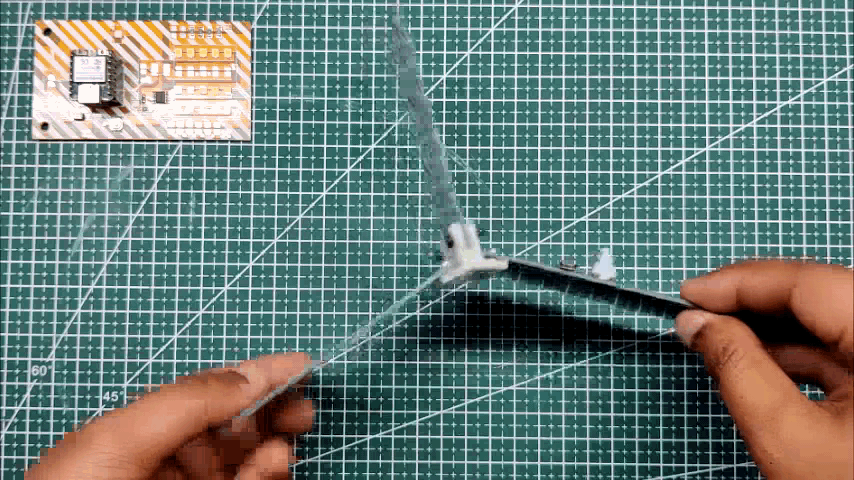
- We begin the Main assembly by gathering all of the components after uploading and testing the LED Board.
- We place the 3D Printed Circuit Holder on one PCB and connect it to the other two boards, which will form the bottom stand for the entire lamp structure.
Final Assembly
.gif)
.gif)
.gif)
.gif)
- We place the 3D Printed Circuit Holder on one PCB and connect it to the other two boards, which will form the bottom stand for the entire lamp structure.
- Following that, we connect the TOP LED Board to the base part using two 3D Printed circuit holders and M2 screws.
- Finally, we connect two wires to the Base Board's USB In supply and the LED Board Power IN Port, which will be used later to power this setup via USB.
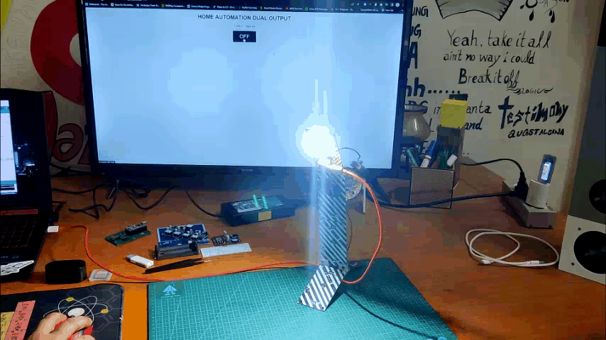
RESULT
.gif)
.gif)
.gif)
We copy the IP address we got earlier from the serial monitor and paste it into our web browser (Chrome).
This lamp's web server will open up and have a button for changing the state of the LED from low to high.
By making changes in code, we can add a slider to this webpage, which will allow us to alter the brightness level, which will improve this project a bit more.
Overall, this Web desk lamp, which uses Chrome to access its webpage, is a great example of the integration of electronics and software to create a functional and innovative device.
That's all for today, folks. If this article was helpful or you need any assistance with this project, please leave a comment.
Peace.