Weather Station Using NodeMCU ESP8266
by IoTFever in Circuits > Arduino
3244 Views, 4 Favorites, 0 Comments
Weather Station Using NodeMCU ESP8266
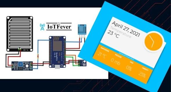
Hello friends welcome back again, i hope you doing great, In todays tutorial we are making Live Weather station ESP8266 Microcontroller. Have you ever been curious to know whats the live weather status exactly where you live, many people use weather application by choosing the city name to get the data from weather stations but that’s not mostly accurate to your live location. So here we making advanced an interesting project to make a live weather station at home with ESP8266 – 12E based NodeMCU and monitor temperature, humidity, Barometric pressure and rainfall status over local web server by using Mobile phone or computer.
Let’s Start your project…..
Required Components
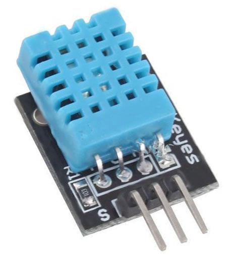
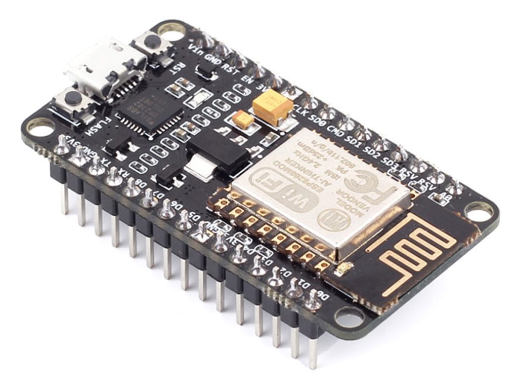
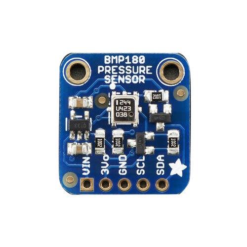
- NodeMCU ESP8266
- DHT11 temperature and humidity sensor
- BMP180 or BMP280 Barometric pressure sensor
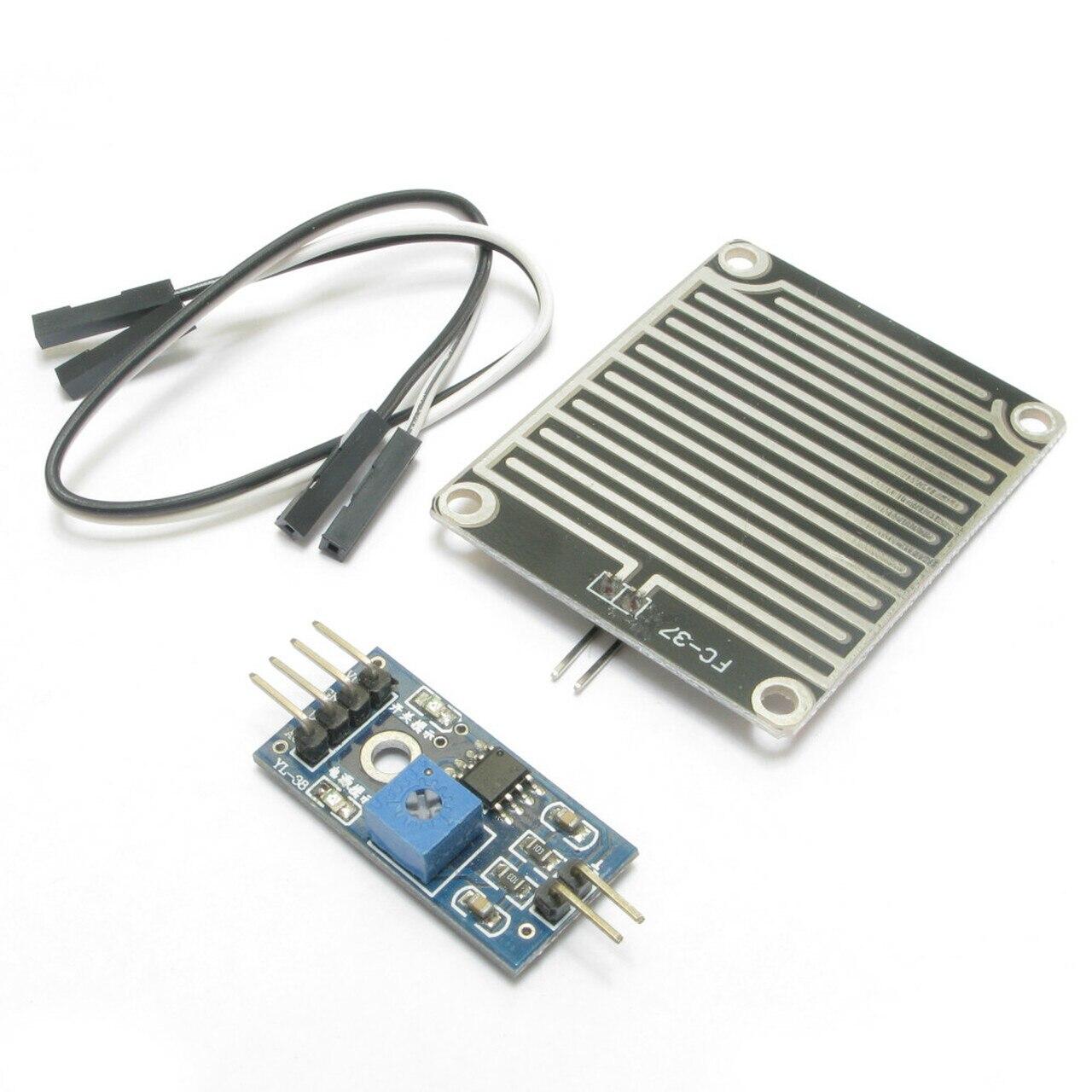
- Rain sensor module FC-37
- Resistors 4.7 K ohm
- Few connection wires
Required Software
Arduino Software Link
Sensor Details
DHT11 temperature and humidity sensor:
This sensor is an easy to use temperature and humidity sensor with attractive cheap price. It allows us to get both temperature and humidity data from single board instead of using two.
It comes in two types one is only the sensor with 4 pins on it and the other one is sensor fitted on a PCB which includes an 5 kΩ pull up resistance and a on board LED which indicates the data usage. Both has same functionality only new difference is the price and connection pins. It works in the voltages between 3 volts and 5 voltswith the temperature measurement range from 0 to 50 degree centigrade.Accuracy ± 2 ° CResolution Temperature: 0.1 ° CHumidity measurement range: 20% to 90% RH.Humidity measurement accuracy: 5% RH.Humidity Resolution: 1% RHSensing time: 1 sec.
Rain Sensor:
This type of sensor detects the presence of rain due to the variation in the conductivity of the sensor when it comes into contact with water. There are several similar sensor models, such as the FC-37 and the YL-83.
Constructively they are simple sensors. There are two contacts, connected to conductive tracks interlocked with each other at a small distance, without contact between them. When water is deposited on the surface, both conductors are placed in electrical contact, which can be detected by a sensor. Both models are shipped with a standard measurement plate with the LM393 comparator, which allows the reading to be obtained both as an analog value and digitally when a certain threshold is exceeded, which is regulated through a potentiometer located on the plate itself. Analog values measured range from 0 for a fully soaked plate to 1023 for a completely dry plate .
BMP180 Barometric Pressure Sensor:
A bmp180 sensor is a printed circuit board, which includes a high-precision absolute barometric / atmospheric pressure sensor (atmospheric pressure is the force per unit area that air exerts on Earth’s surface), it has a measurement range between 300 and 1100 hPa (Hecto Pascal) and an error margin of 0.03 hPa, it also has a temperature sensor and by means of software it allows calculating the altitude with respect to the sea.
The pressure sensor is based on piezo-resistive technology with high efficiency, linearity and long duration, it has a power range of between 1.8 volts and 3.6 volts dc (direct current), so if we are going to use it With a micro controller running at 5 volts, we will need level adapters on the SDA (data line) and SCL (clock line) pins of the I2C bus. I currently have the model on the left and the central one, both are the same, except that the central module has an integrated 3.3 volt source, it can be powered at 5 volts on the pin marked Vcc, but it can also be powered with 3.3 volts on the pin marked 3.3 volts.
Connecting the Hardware
- Nodemcu D1 pin to DHT11 data pin
- Nodemcu 3.3 pin to DHT11 VCC pin
- Nodemcu GND pin DHT11 GND pin
- Nodemcu D7 pin to BMP180 SCL pin
- Nodemcu D8 pin to BMP180 SDA pin
- Nodemcu 3.3 pin to BMP180 VCC pin
- Nodemcu GND pin to BMP180 GND pin
- Nodemcu A0 pin to Rain sensor A0 pin
- Nodemcu 3.3 pin to Rain sensor 3.3 pin
- Nodemcu GND pin to Rain sensor GND pin
Circuit Diagram
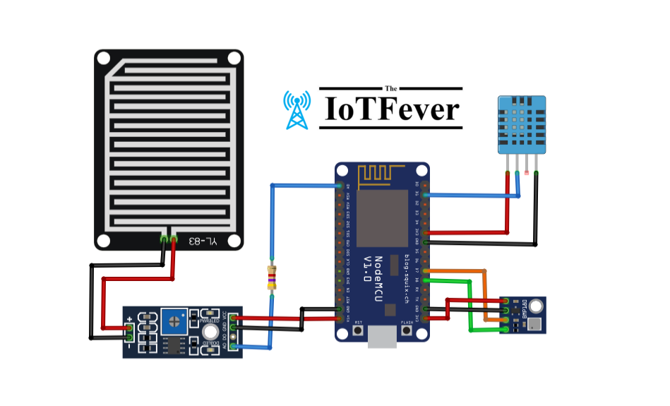
Interfacing DHT11, BMP180 and rain sensor with NodeMCU to built Weather station
Here we are interfacing the sensors with nodemcu both dht11 and BMP 180 are connected directly without using any external resistance but for rain sensor we are using 2 4.7K ohm resistors.
Setting Up Arduino IDE
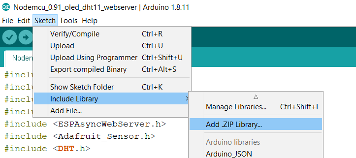
After download open Arduino IDE software Click on Sketch ==> include library ==> Add .Zip library
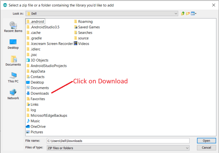
Click on download folder and search for “ESP8266WebServer” library and click on it, similarly do for other library
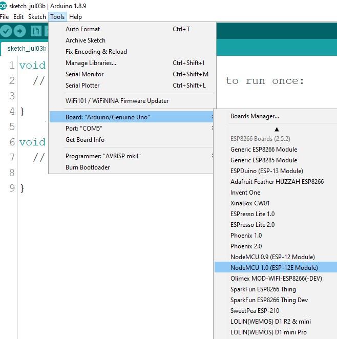
Now open Arduino IDE software, next to select the board go to Tools ==> Board ==> and search for NodeMCU 1.0(ESP-12E Module) and click on it.
If you don’t have Nodemcu board installed then follow the procedure link. Link
Arduino IDE Code
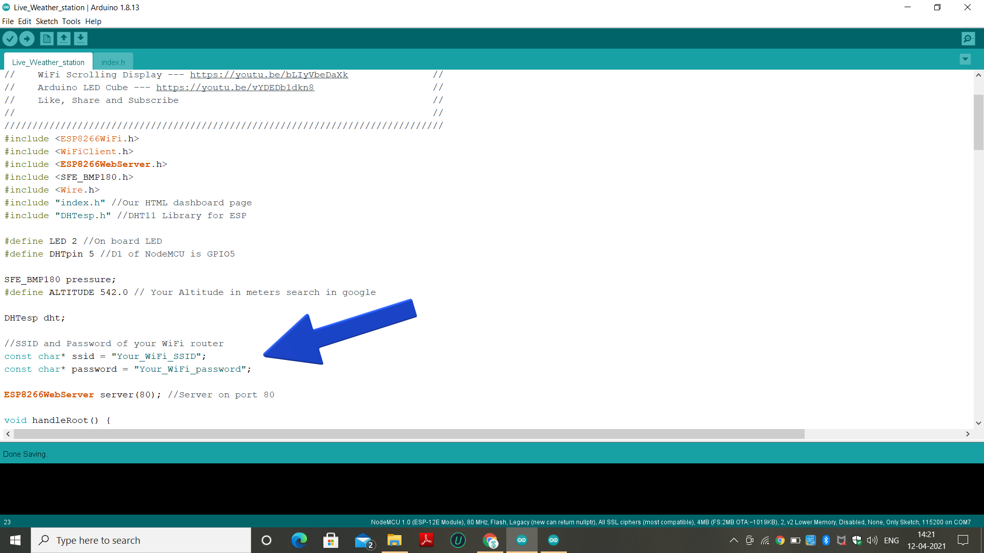
To get the Arduino code go to link Code Link (paid)
Then, Download the source code. We need to do some changes, just change your “wifi ssid” and “wifi password”.
Working of Live Weather Station Using ESP8266
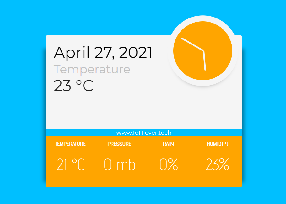
After connecting and uploading the code to the nodeMCU open serial monitor to find the IP address assigned to the device just copy the address and paste in any web browser connected in the same network to display the Live weather monitoring dashboard.
That’s it for this tutorial. Thanks for reading.
If you have any question about today’s tutorial, please feel free to share via the comment section. I hope it will helpful to you……….Thanks.