Weather Station Based on STONE LCD and Arduino
by greyli1987 in Circuits > Arduino
787 Views, 3 Favorites, 0 Comments
Weather Station Based on STONE LCD and Arduino
Description
A weather station is a facility, either on land or sea, with instruments and equipment for measuring atmospheric conditions to provide information for weather forecasts and to study the weather and climate. But here we are going to build, which will detect the atmospheric temperature and humidity. In this project we will use the DHT-11 sensor which has the capability to detect both things temperature and humidity, then this information we will send to the STONE-HMI display with the help of Arduino, so let’s start. First will design the GUI part then go for the circuit part let’s jump to the GUI design.
GUI Design
For this project, we are using a TFT display(STONE-HMI), this display has a software that is GUI software with this help we are going to design an interface that will contain a designed image that will display the temperature and humidity.
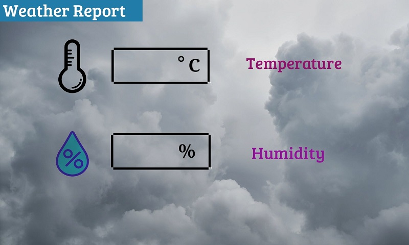
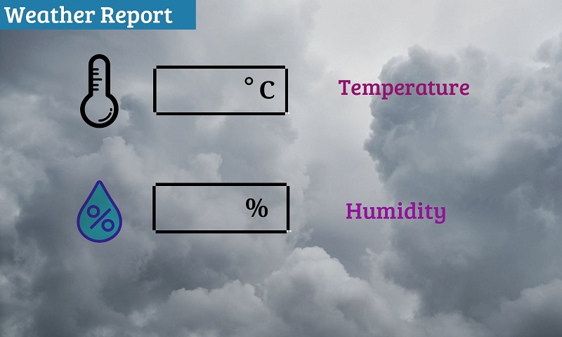
For the GUI design first, you have to design an image on which you are going to display temperature & humidity. Here our design is this if you want you can design any other whatever you want.
But remember one thing the image which are you going to edit this should be in the same resolution as your screen resolution, here we are using a 5’’ display so the resolution of this is [800X480] so we have selected for this at the time of new project selection.
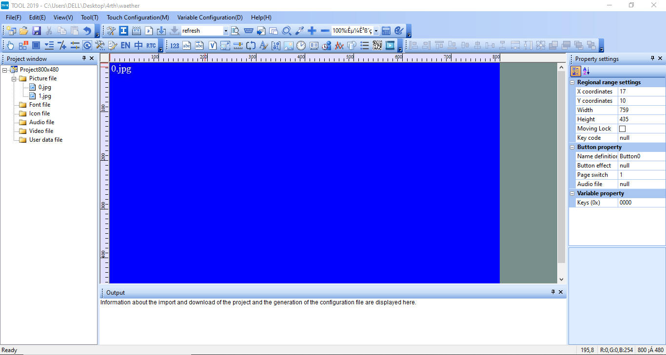
After selecting a new project and done with screen size selection then you will get a blue screen interface like this.
As you can see there is a picture file right click on that and add an image which you have designed here we have added the image as ‘1.jpg’ you can see in the image.
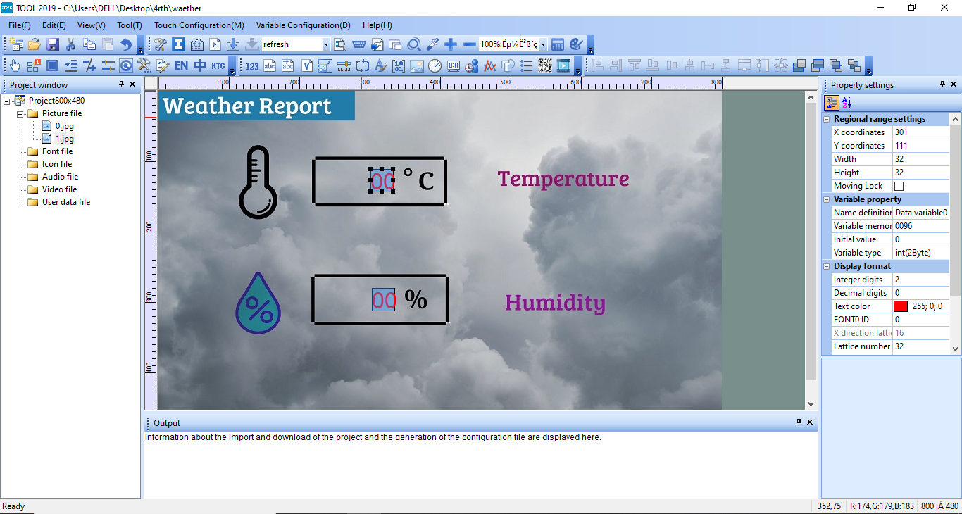
After adding this deigned image now go to that designed image and take the ‘data variable’ from the function which is given on the top and select for temperature and humidity as well.
For both select two integer values as you can see on the right side we have selected two integers.
Now come to the data sending part for this you have to select ‘variable memory address ‘ and then type the address in that here we have used address ‘0096’ for displaying temperature and ‘0086’ for humidity if you want you can use a different address but according to that, you have to change in the code also. So after done this part let’s move to how the sensor & code is working.
Circuit-Diagram
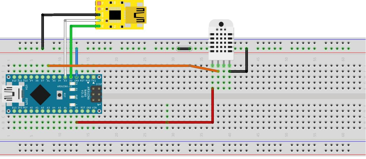
In this circuit, there are two things that are connected with Arduino first is display and another one is a sensor that sending the data to the Arduino then Arduino sending the data to display using the software-serial library.
How DHT-11 Sensor Is Working
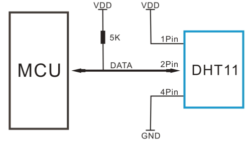

The DHT11 is a commonly used temperature and humidity sensor. The sensor comes with a dedicated NTC to measure temperature and an 8-bit microcontroller to output the values of temperature and humidity as serial data. The sensor is also factory calibrated and hence easy to interface with other microcontrollers.
This DHT11 sensor can measure temperature from 0°C to 50°C and humidity from 20% to 90% with an accuracy of ±1°C and ±1%. So as you saw this temperature gives us accurate value so these are the reasons we have used this sensor in this project. The DHT11 sensor is factory calibrated and outputs serial data and hence it is highly easy to set it up. The connection diagram for this sensor is shown in the picture. This is the same connection as we have given above in the circuit.
As you can see the data pin is connected to an I/O pin of the MCU. This data pin outputs the value of both temperature and humidity as serial data and this data we are sending using the serial library but for this sensor output, we also required a DHT11 library so first, we have added in our code we will discuss this in the code section.
The output given out by the data pin will be in the order of 8bit humidity integer data + 8bit the Humidity decimal data +8 bit temperature integer data + 8bit fractional temperature data +8 bit parity bit. To request the DHT11 module to send these data the I/O pin has to be momentarily made low and then held high as shown in the timing diagram picture.
Arduino Code
#include "DHT.h"
#define DHTPIN 6 // Digital pin connected to the DHT sensor
#define DHTTYPE DHT11 // DHT 11
DHT dht(DHTPIN, DHTTYPE);
#include <SoftwareSerial.h>
SoftwareSerial screenserial(2, 3); // RX, TX
#define hd 0x86
#define td 0x96
unsigned char h_send[8]= {0xA5, 0x5A, 0x05, 0x82, 0x00, hd, 0x00, 0x00};
unsigned char t_send[8]= {0xA5, 0x5A, 0x05, 0x82, 0x00, td, 0x00, 0x00};
void setup()
{
Serial.begin(115200);
screenserial.begin(115200);
Serial.println(F("DHTxx test!"));
dht.begin();
}
void loop()
{
// Wait a few seconds between measurements.
delay(1000);
// Reading temperature or humidity takes about 250 milliseconds!
// Sensor readings may also be up to 2 seconds 'old' (its a very slow sensor)
int h = dht.readHumidity();
// Read temperature as Celsius (the default)
int t = dht.readTemperature();
// Check if any reads failed and exit early (to try again).
if (isnan(h) || isnan(t))
{
Serial.println(F("Failed to read from DHT sensor!"));
return;
}
Serial.print(F(" Humidity: "));
Serial.print(h);
Serial.print(F("% Temperature: "));
Serial.print(t);
Serial.println(F("C "));
h_send[6]=h/256;
h_send[7]=h%256;
screenserial.write(h_send,8);
t_send[6]=t/256;
t_send[7]=t%256;
screenserial.write(t_send,8);
}
Output Video
As we have discussed we are using the software-serial library to transfer the key-value over an address, this we have added in this code, this is giving an interface to connect with Arduino and STON-HMI display, and for the purpose of sensor we have added a library, #include "DHT.h" this library giving both temperature and humidity value as we have discussed in the timing diagram.
For humidity here we have defined the address as ‘0x86’ over this address we are sending 8-bit data as you can see in the last of the code similarly we have defined for temperature and done the same thing, remember both codes and in the display, the part address should be same otherwise it will not work. So with this project is completed now, see the output video.