Wearable Tech: Voice-Changing Glove
by sadboyz2002 in Circuits > Wearables
895 Views, 7 Favorites, 0 Comments
Wearable Tech: Voice-Changing Glove
Well, it seems like gloves with incredible powers are all the rage these days. While Thanos’ Infinity Gauntlet is a pretty powerful glove, we wanted to make a glove that could do something even more remarkable: change the wearer’s voice in real-time.
This Instructable provides a walkthrough of how we designed a voice-changing glove. Our design utilized various sensors and a microcontroller in the glove to detect motions, which were sent via an Arduino code to a Max patch, where our audio signal was then altered and distorted in fun ways. The specific sensors, motions, and sound alterations we used are all flexible for different considerations; this is just one way to create a voice-changing glove!
This project was part of a community partnership between Pomona College students and the Fremont Academy of Engineering Femineers. It’s a real fun mix of electronic engineering and electronic music elements!
Materials
Parts:
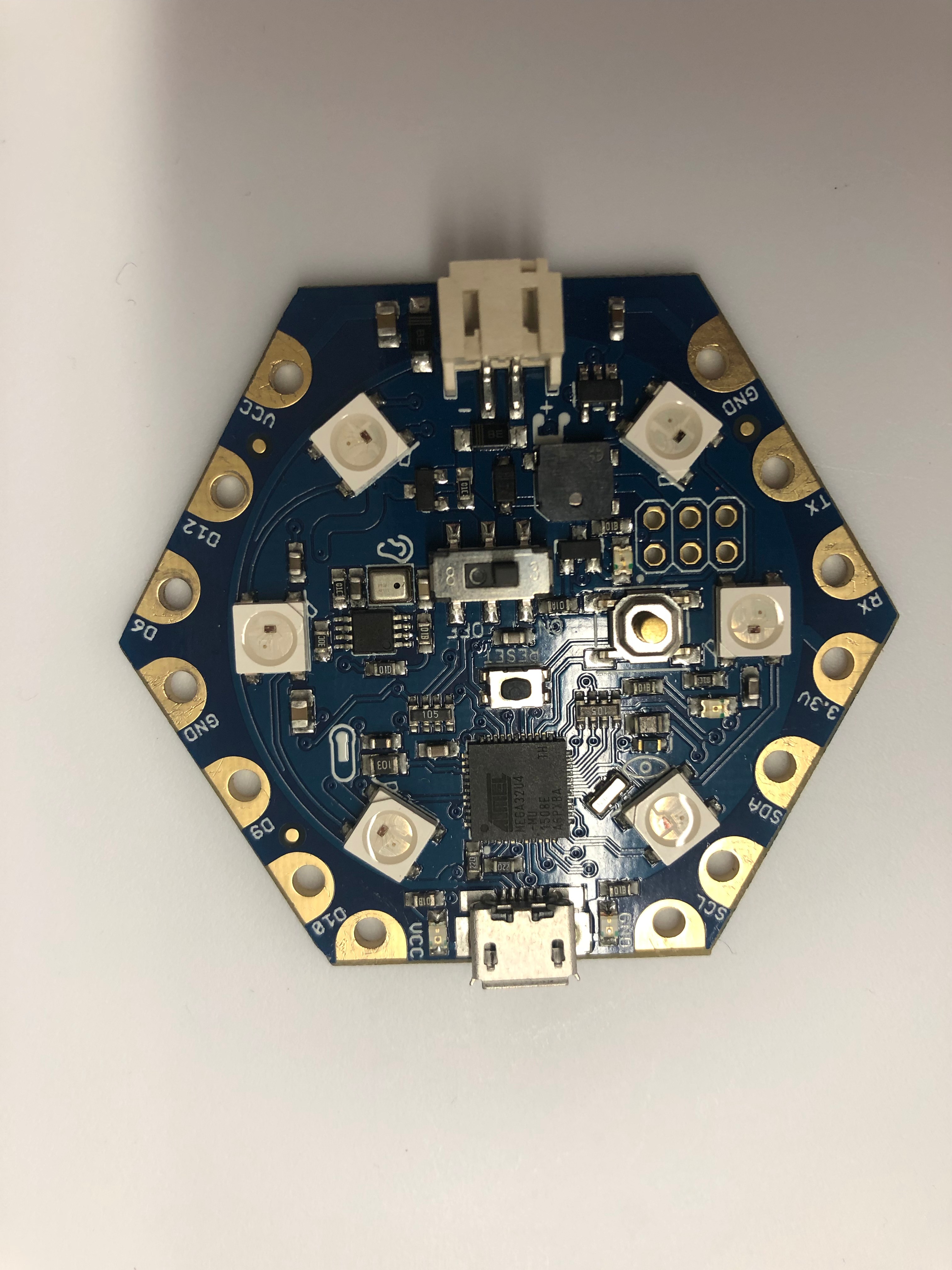
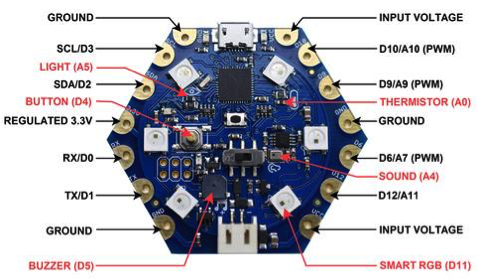
- HexWear Microcontroller (ATmega32U4) (http://hexwear.com/)
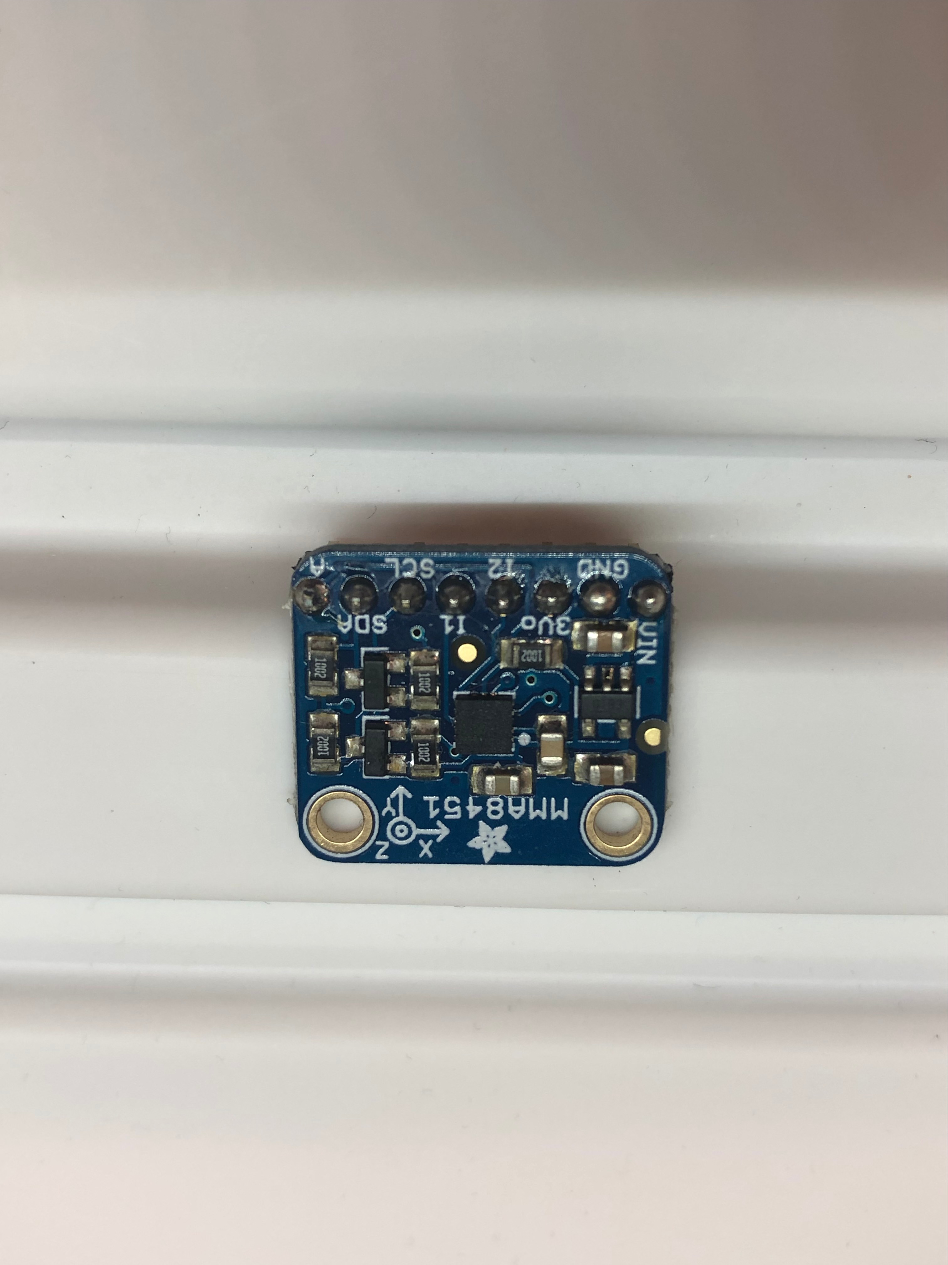
- MMA8451 Accelerometer (https://www.adafruit.com/product/2019)
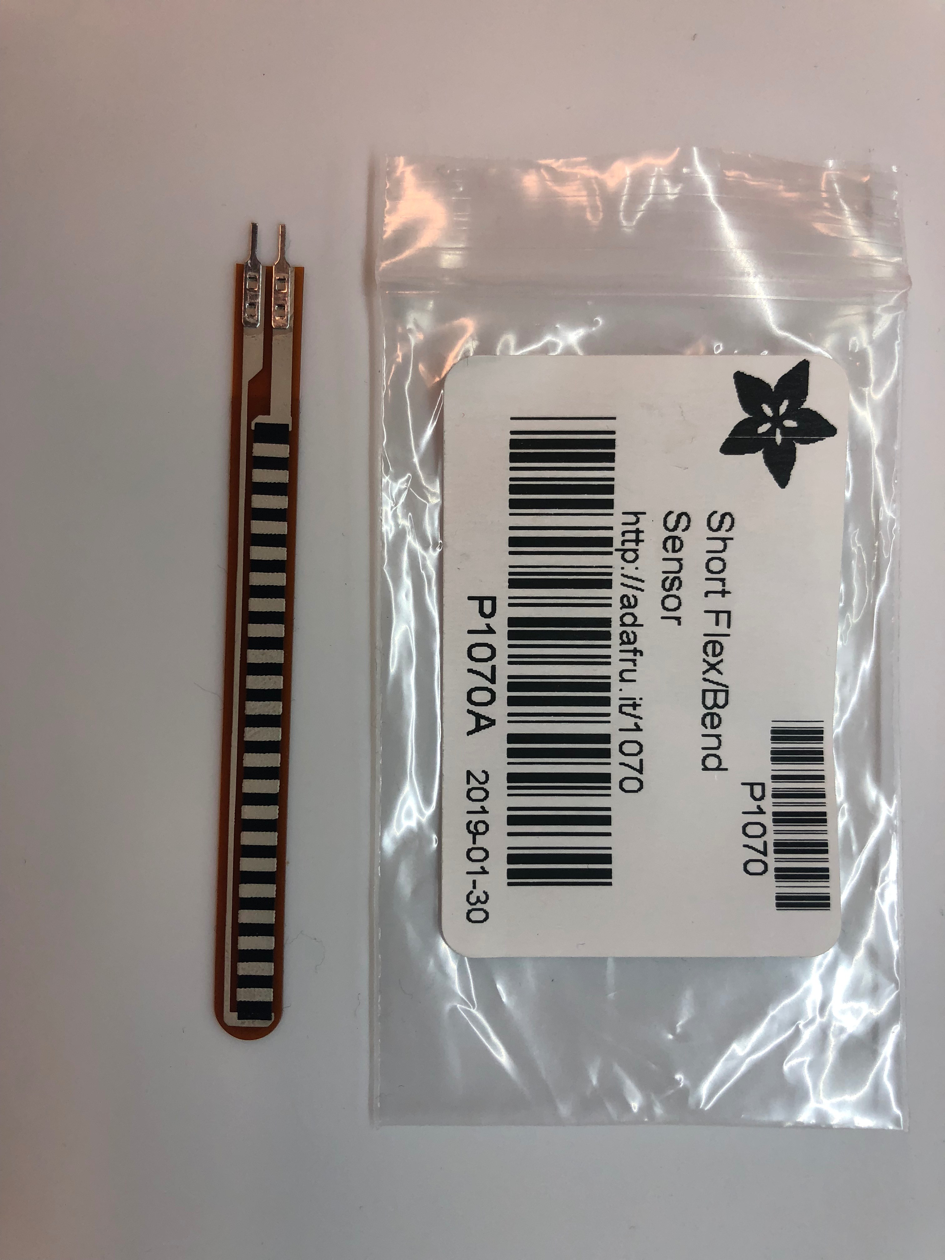
- Short Flex Sensors (x4) (https://www.adafruit.com/product/1070)
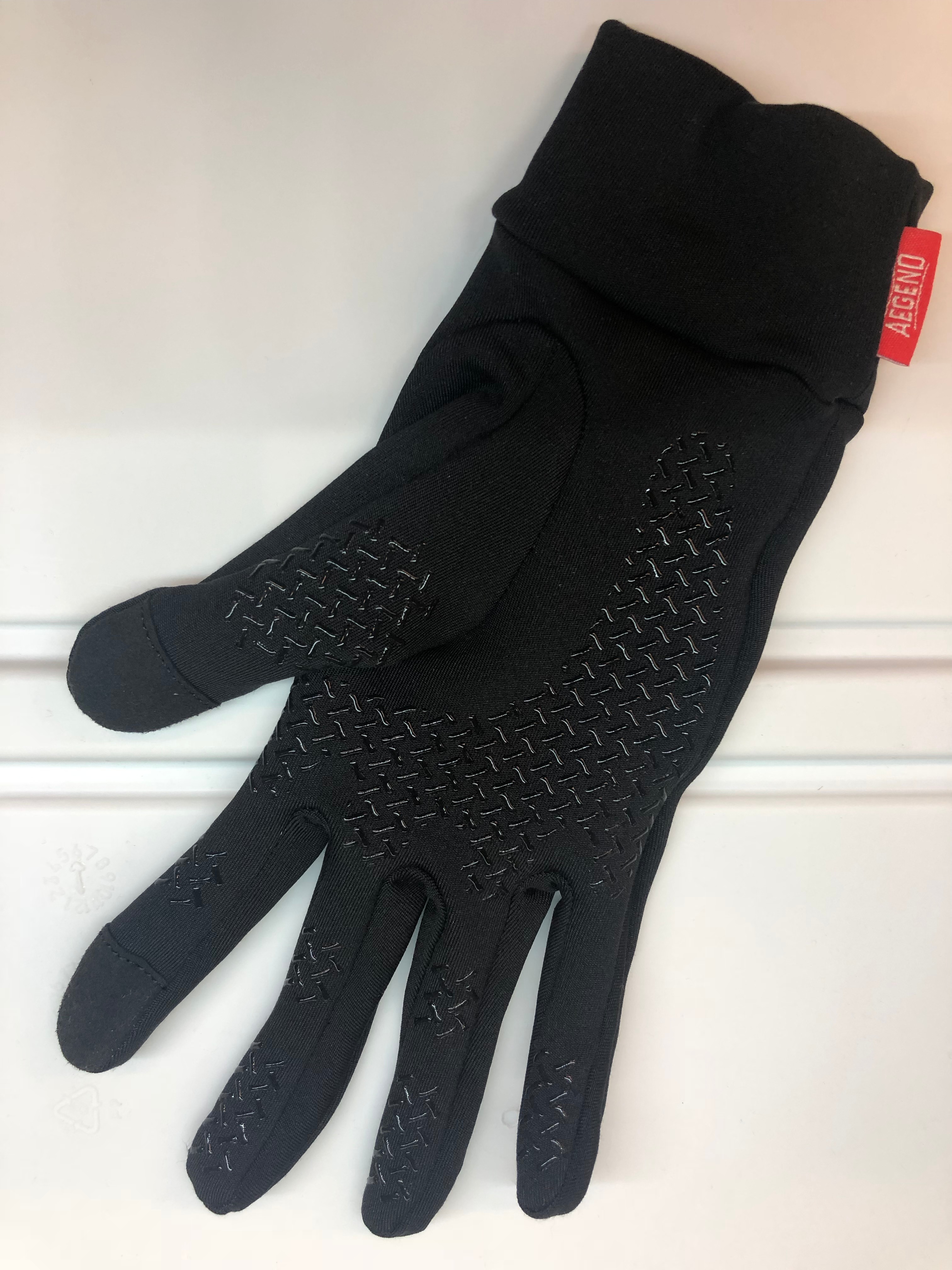
- Lightweight running glove
- #2 screws and washers (x8)
- Crimp terminal connectors; 22-18 gauge (x8) (https://www.elecdirect.com/crimp-wire-terminals/ring-crimp-terminals/pvc-ring-terminals/ring-terminal-pvc-red-22-18-6-100pk)
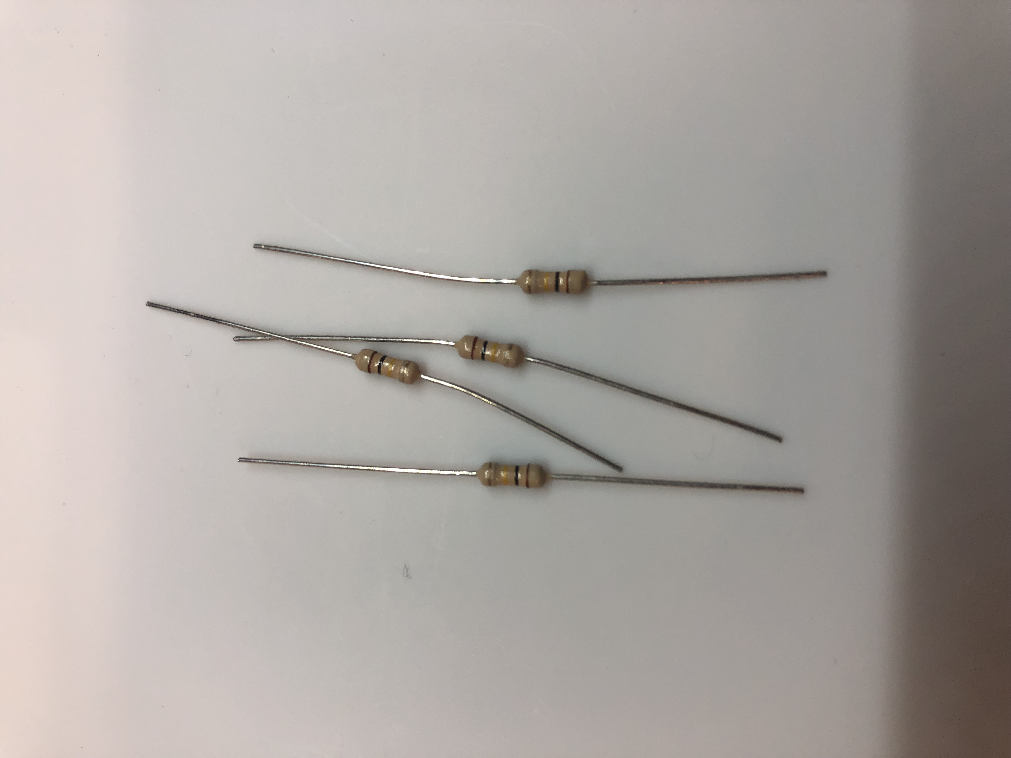
- 50kΩ resistor (x4)
- Wire (~20 gauge)
- Self-adhesive safety pin
- Felt or other fabric (~10 sq. in.)
- Sewing thread
- Zipties
- Laptop
- USB Microphone
Tools:
- Soldering kit
- Wire strippers and wire cutters
- Electrical tape
- Hot air gun
- Screwdriver
- Scissors
- Sewing needle
Software:
- Max by Cycling '74 (https://cycling74.com)
- Arduino software (https://www.arduino.cc/en/Main/Software)
Installing the Software
We get to start with what is truly the most exhilarating part of any project: installing libraries (and more).
Arduino:
Dowload and install the Arduino software (https://www.arduino.cc/en/Main/Software).
HexWear:
1) (Windows only, Mac users can skip this step) Install the driver by visiting https://www.redgerbera.com/pages/hexwear-driver-installation. Download and install the driver (the .exe file listed on Step 2 at the top of the linked RedGerbera page).
2) Install required library for Hexware. Open the Arduino IDE. Under “File” select “Preferences.” In the space provided for Additional Boards Manager URLs, paste
https://github.com/RedGerbera/Gerbera-Boards/raw/master/package_RedGerbera_index.json.
Then click “OK.”
Go to Tools -> Board: -> Board Manager. From the upper lefthand corner menu, select “Contributed.”
Search for, and then click on Gerbera Boards and click Install. Quit and reopen Arduino IDE.
To ensure that the library is installed properly, go to Tools -> Board, and scroll to the bottom of the menu. You should see a section entitled “Gerbera Boards,” under which there should at least appear HexWear (if not more boards like mini-HexWear).
Accelerometer:
Download and install the accelerometer library (https://learn.adafruit.com/adafruit-mma8451-accelerometer-breakout/wiring-and-test)
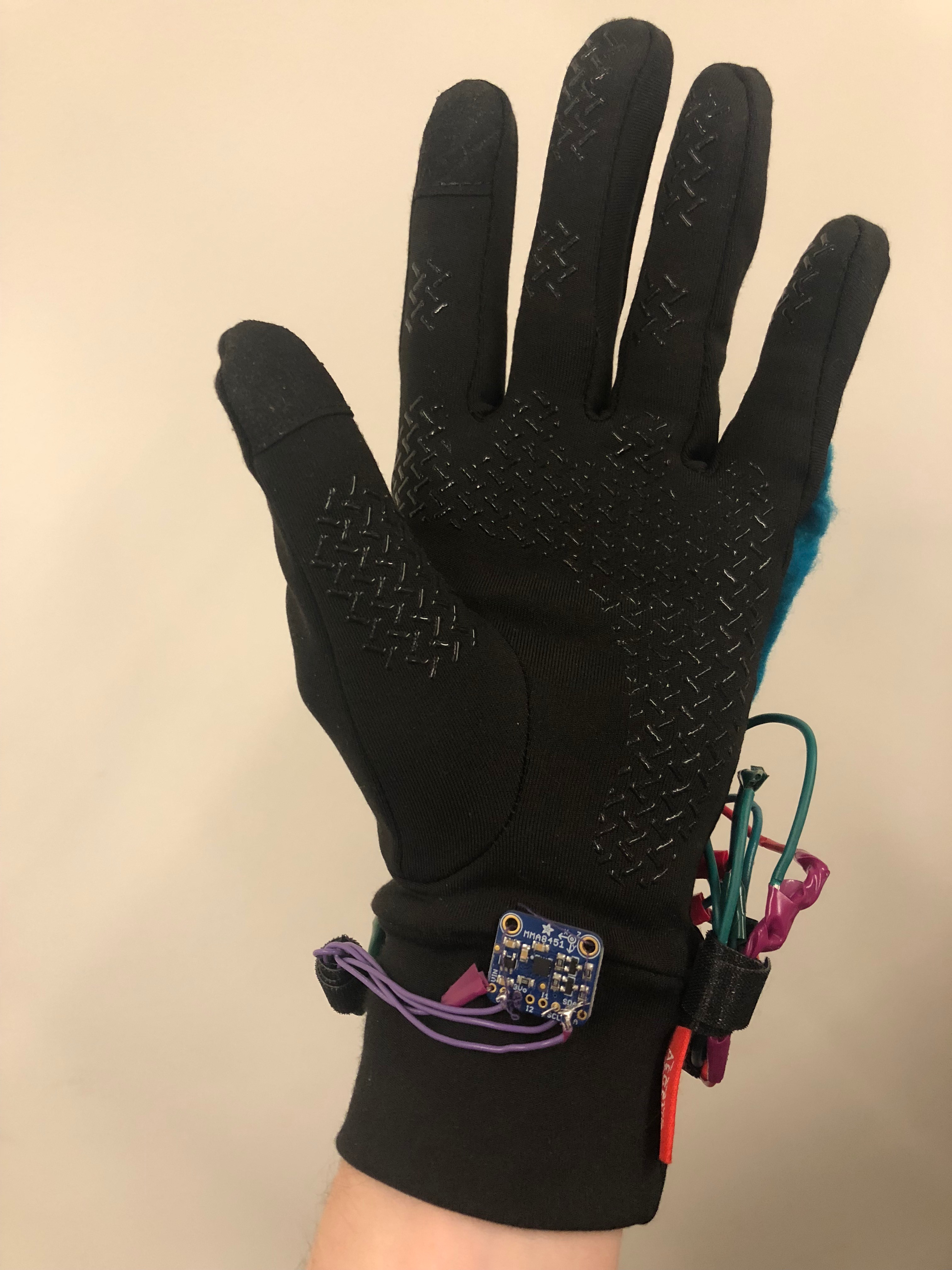
Attaching the Accelerometer
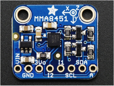
We need two main types of sensors in order to interact with this project: an accelerometer, and flex sensors. We’ll examine these one at a time, starting with the accelerometer. First, we need the hardware connections to match up.
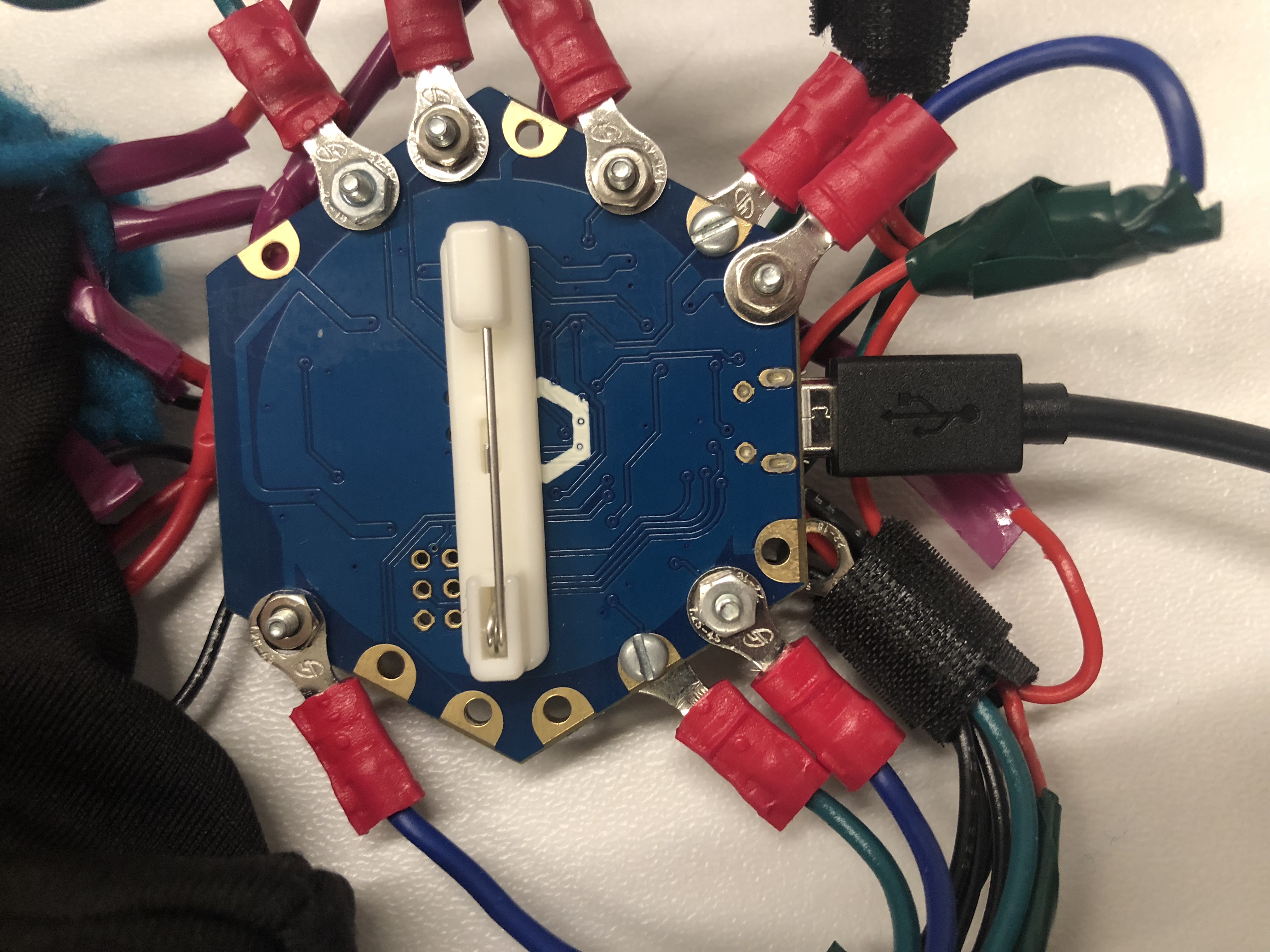
In order to avoid damaging your Hex, we recommend putting a #2 screw and washer through the desired ports, then attaching all connections to that screw. To prevent anything from coming loose when playing with the glove, connections should be soldered and/or crimped. Using a few inches of wire for each connection, make the following connections from the Hex to the accelerometer (see the pinouts above for reference):
INPUT VOLTAGE --> VIN
GROUND --> GND
SCL/D3 --> SCL
SDA/D2 --> SDA
With everything wired up, we’re ready to test!
As a test, run the accelerometer sample code in Arduino (File->Examples->Adafruit_MMA8451->MMA8451demo), making sure that it can output to the Serial monitor. It should output the acceleration due to gravity (~10m/s) in the z direction when held level. By tilting the accelerometer, this acceleration will be measured in the x or y direction; we’ll use this to allow the wearer to change the sound by rotating their hand!
Now, we need to present the accelerometer data in such a way that it can be interfaced with Max. To do so, we must print the values of x and y, perhaps modified to match the desired range (see Part 6). In our code attached here, we do the following:
<pre>//Measure the<br>x-direction and y-direction. We divide and multiply to get into the right ranges
for MAX (range of 1000 in x and range of 40 in y)
xdir = event.acceleration.x/0.02;
ydir = abs(event.acceleration.y)*2;


//Print everything in
a readable format for Max - with spaces between each number
Serial.print(xdir);
Serial.print(" ");
This should have the Hex printing the modified values of the x and y directions of the accelerometer every line. Now we’re ready to add the flex sensors!
Downloads
Attaching the Flex Sensors
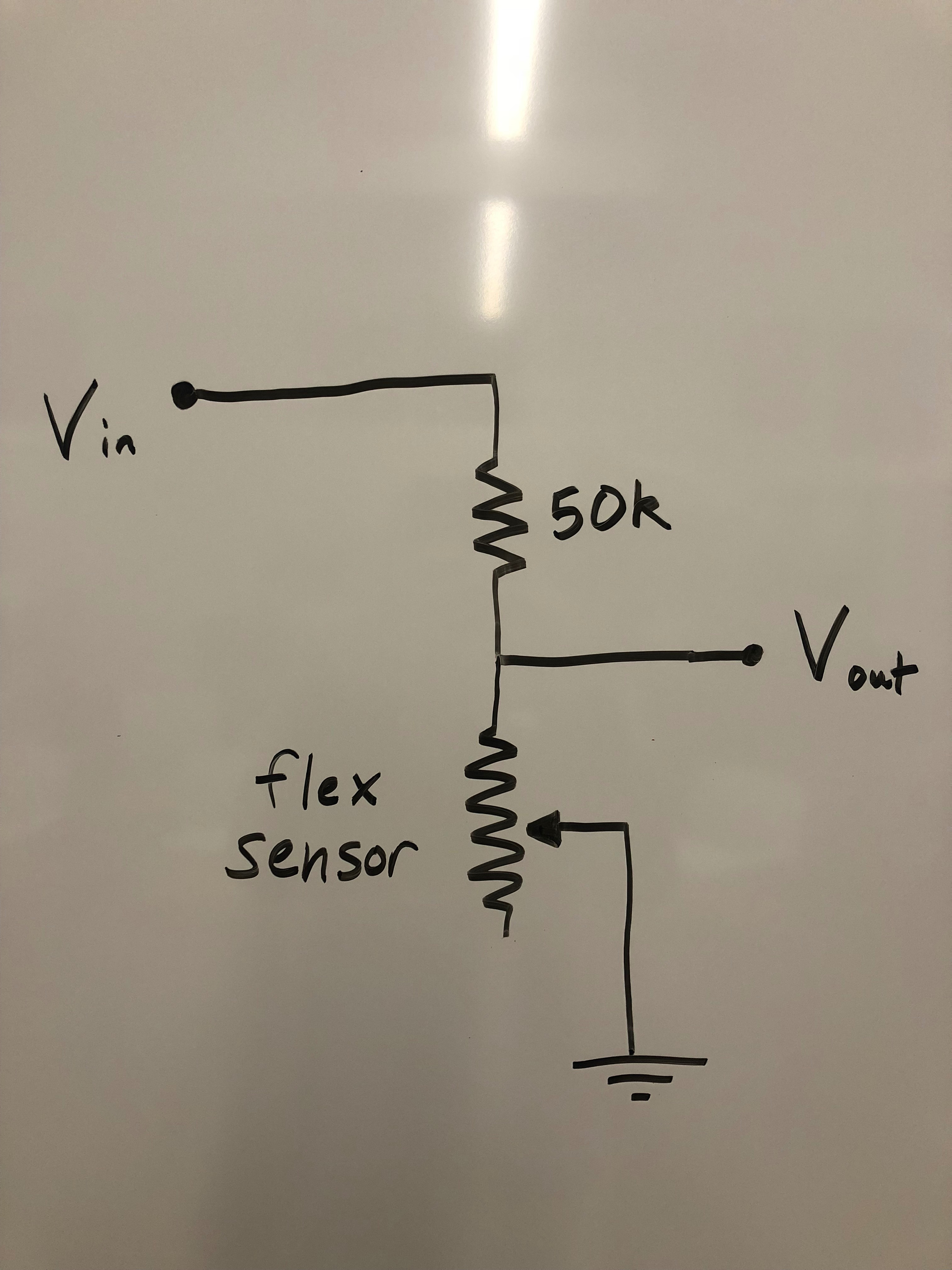

The wearer can get lots of potential sound controls if we can detect bending fingers. The flex sensors will do just that. Each flex sensor is essentially a potentiometer, where unflexed has a resistance of ~25KΩ, while fully flexed has a resistance of ~100KΩ. We put each flex sensor in a simple voltage divider with a 50K resistor, as shown in the first image.
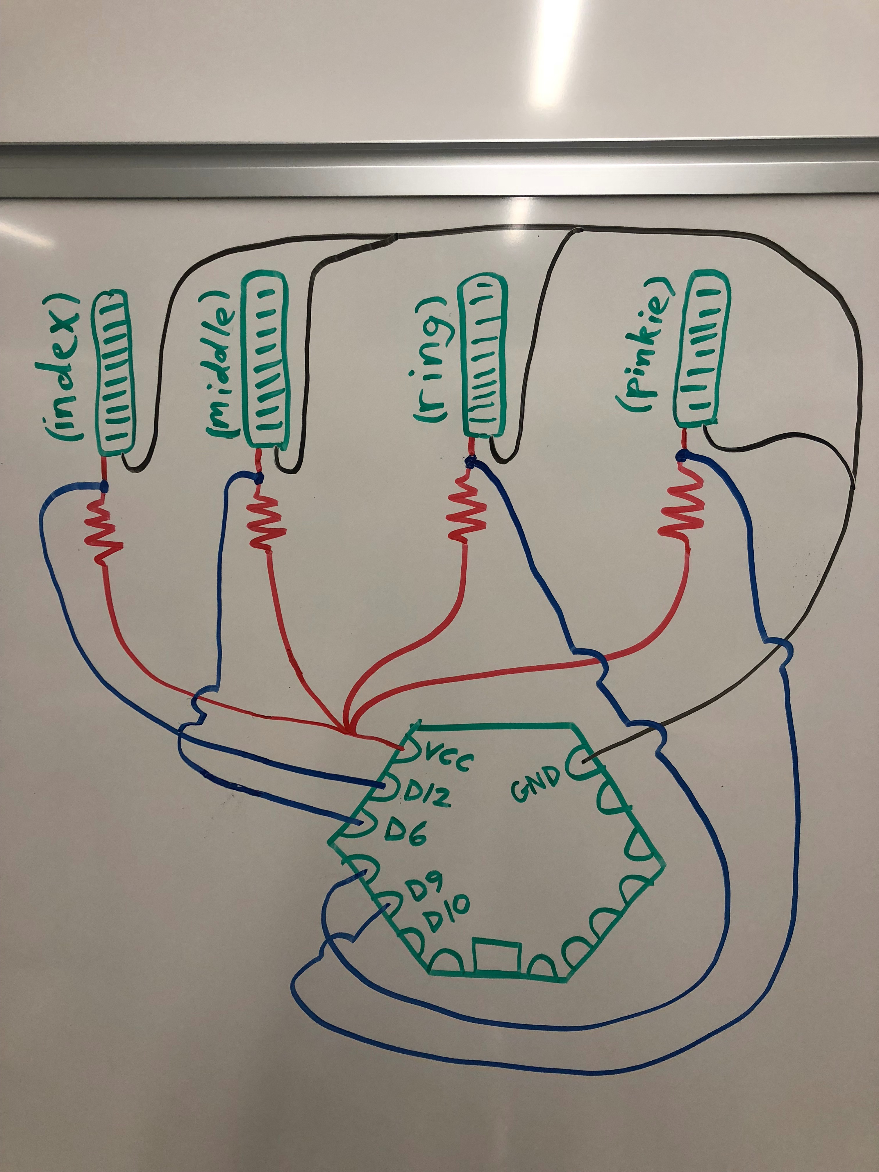
Again using fairly short lengths of wire (keep in mind this will all be fitting onto the back of a glove), solder four voltage divider modules. The four modules will share the same Vin and ground—we twisted together the stripped ends of the wires so we would have just one lead to solder. Finally, take the four modules and make the connections shown in the second image (if anyone knows how to do this without making a horribly tangled mess, please reveal your secrets).
Now, we need the Arduino code to read in the voltages from each sensor. For our purposes, we treated the flex sensors as switches; they were either on or off. As such, our code simply sets a voltage threshold—above this threshold, we output a 1 to the Serial port (meaning the sensor is bent), otherwise we output a 0:
// Take a number of
analog samples and add them up for each Flex sensor    while (sample_count <
NUM_SAMPLES) {
sum10 += analogRead(A10);
sum9 += analogRead(A9);
sum7 += analogRead(A7);
sum11 += analogRead(A11);
sample_count++;
//Short delay to not take them too quickly
delay(5);    }    // calculate the voltage,
averaging over the rapid samples    // use 5.0 for a 5.0V ADC
reference voltage    // 5.015V is the calibrated
reference voltage    voltage10 = ((float)sum10 /
(float)NUM_SAMPLES * 5.015) / 1024.0;    voltage9 = ((float)sum9/
(float)NUM_SAMPLES * 5.015) / 1024.0;    voltage7 = ((float)sum7 /
(float)NUM_SAMPLES * 5.015) / 1024.0;    voltage11 = ((float)sum11 /
(float)NUM_SAMPLES * 5.015) / 1024.0;    //Check if each flex sensor
is greater than threshold (thresh) - if so, set the number    //Pinkie finger    if (voltage10 > thresh)
{      //-5 to raise
voice pitch by one octave      flex10 = -10;    }    else flex10 = 0;    //Ring finger    if (voltage9 >
(thresh-0.4)) {      //5 to lower
voice pitch by one octave      flex9 = 5;    }    else flex9 = 0;    //Middle finger    if (voltage7 > thresh) {      //1 to set
reverb effect      flex7 = 1;    }    else flex7 = 0;    //Index finger    if (voltage11 > thresh)
{      //50 to set
cycles to 50      flex11 = 93;    }    else flex11 = 0;    //Reset all the counting
variable to 0 for the next loop    sample_count = 0;    sum10 = 0;    sum9 = 0;    sum7 = 0;    sum11 = 0;
At this point, the Serial port should show values for the accelerometer orientation, and also whether each flex sensor is bent. We’re ready to get our Arduino code talking to Max!
Interfacing With Max
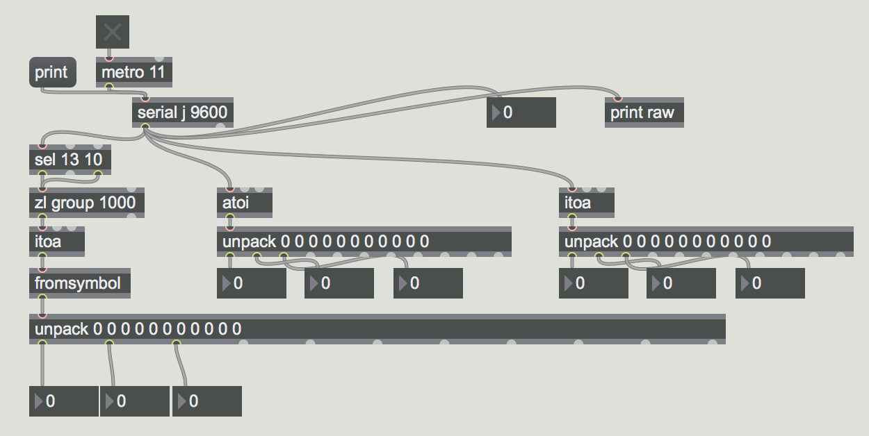
Now that the Hex code is spitting lots of numbers through the Serial port, we need the Max software to read these signals. The block of code pictured above does just that! You’re very welcome.
Important note: after uploading the code to the Hex, close out of all serial port windows, then change the circled letter in the Max code to match the Hex port. If you are unsure of which letter to set, pressing the “print” part of the Max code will list all connected ports.
The printed line from the Hex’s serial port is read through the Max code block, and then split based on the space delimiters. The output at the end of the Max block allows you to grab each number individually, so we will connect the first output space to where we want the x direction of the accelerometer to go, the second space will be the y direction, etc. For now, just connect these to number blocks to ensure that they are working. You should be able to move the accelerometer and flex sensors and see the numbers change in the Max software.
Downloads
Building the Rest of the Max Code
Given the power of the Max language, you can really let your imagination run wild here with all the ways you can alter the incoming sound signal with your magical power glove. Still, if you run out of ideas, above is a rundown of what our Max code does and how it works.
For each parameter you’re trying to alter, you’ll probably want to mess around with the range of values coming from the Arduino code to get just the right sensitivity.
Some other Max troubleshooting tips:
- If you're not hearing sound
- make sure Max is set to receive audio from your microphone (Options --> Audio Status --> Input Device)
- make sure the Master Volume slider in Max is turned up, and any other volume controls you may have in your code
- If the code doesn't seem to be doing anything
- make sure your patch is locked (lock symbol in lower left corner)
- ensure via readouts in the Max patch that your Max patch is still getting data from the Arduino serial port. If not, try resetting the serial port (as outlined in Step 5) and/or checking your physical wiring connections.
- Weird clipping noises when changing parameters
- this is something to do with how ~tapin and ~tapout work; specifically that when you change their values, they reset, which causes the clipping. Given our limited knowledge of the program, we're almost certain there's a better way to do this in Max and eliminate the issue...
Literally Putting It All Together
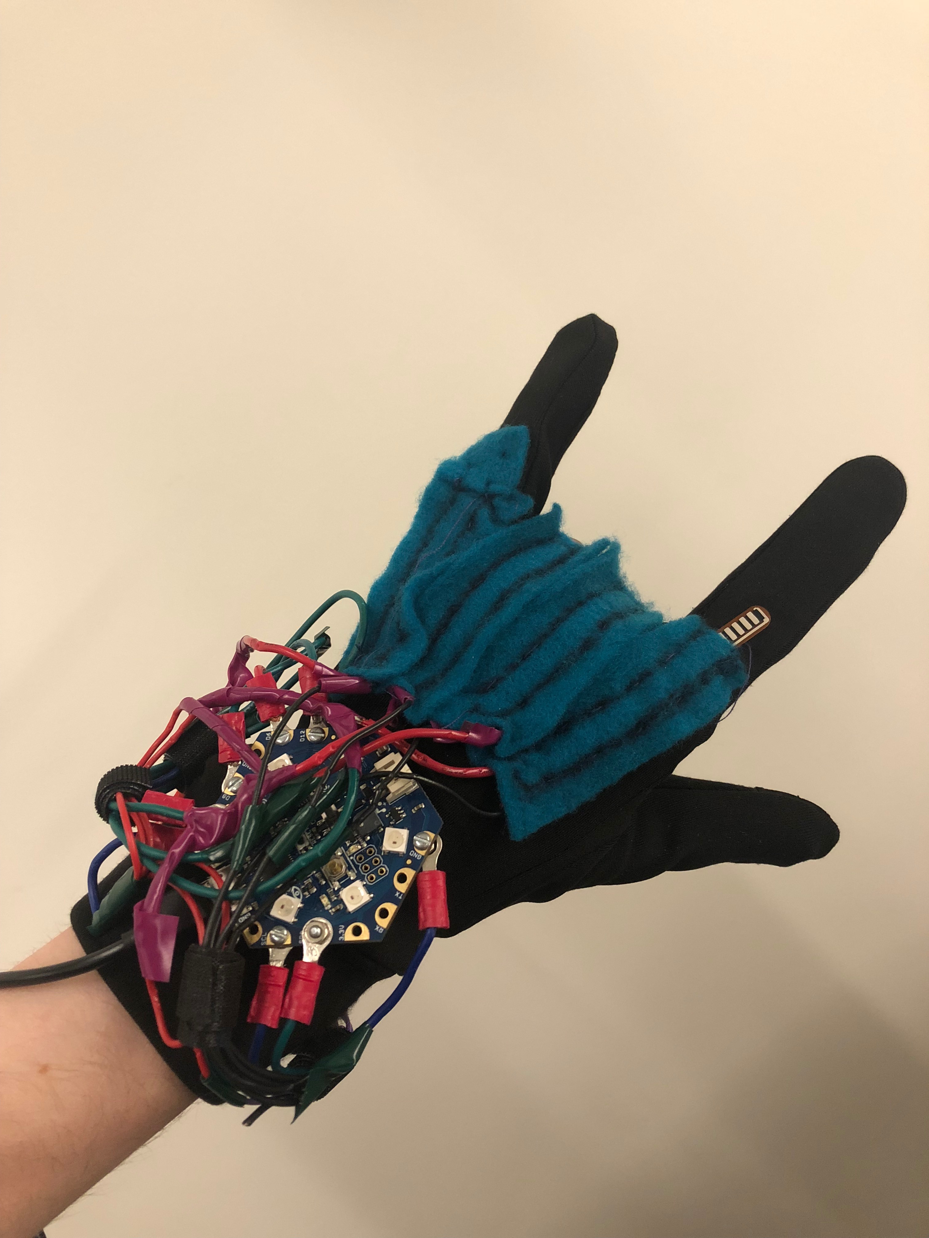
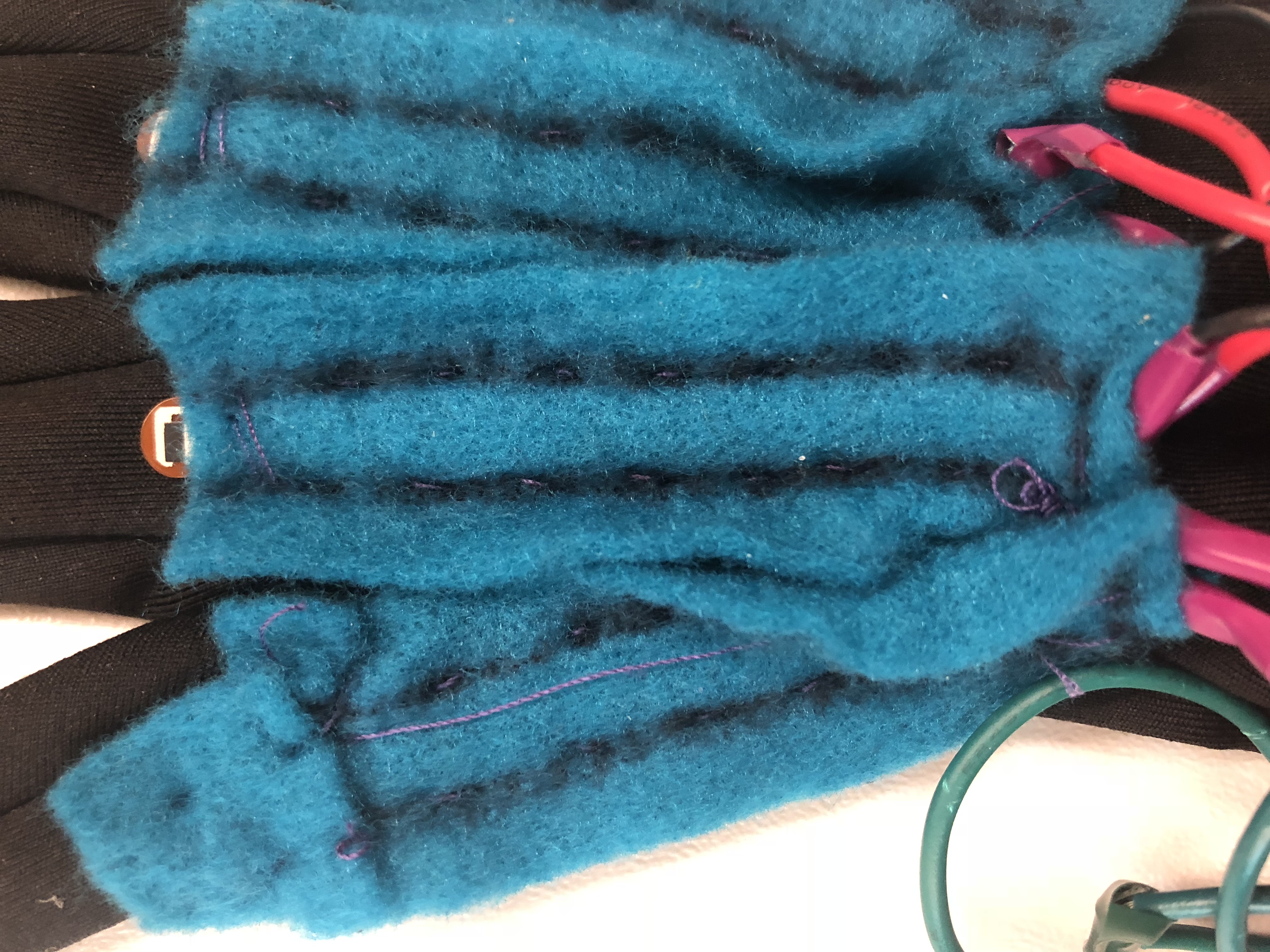
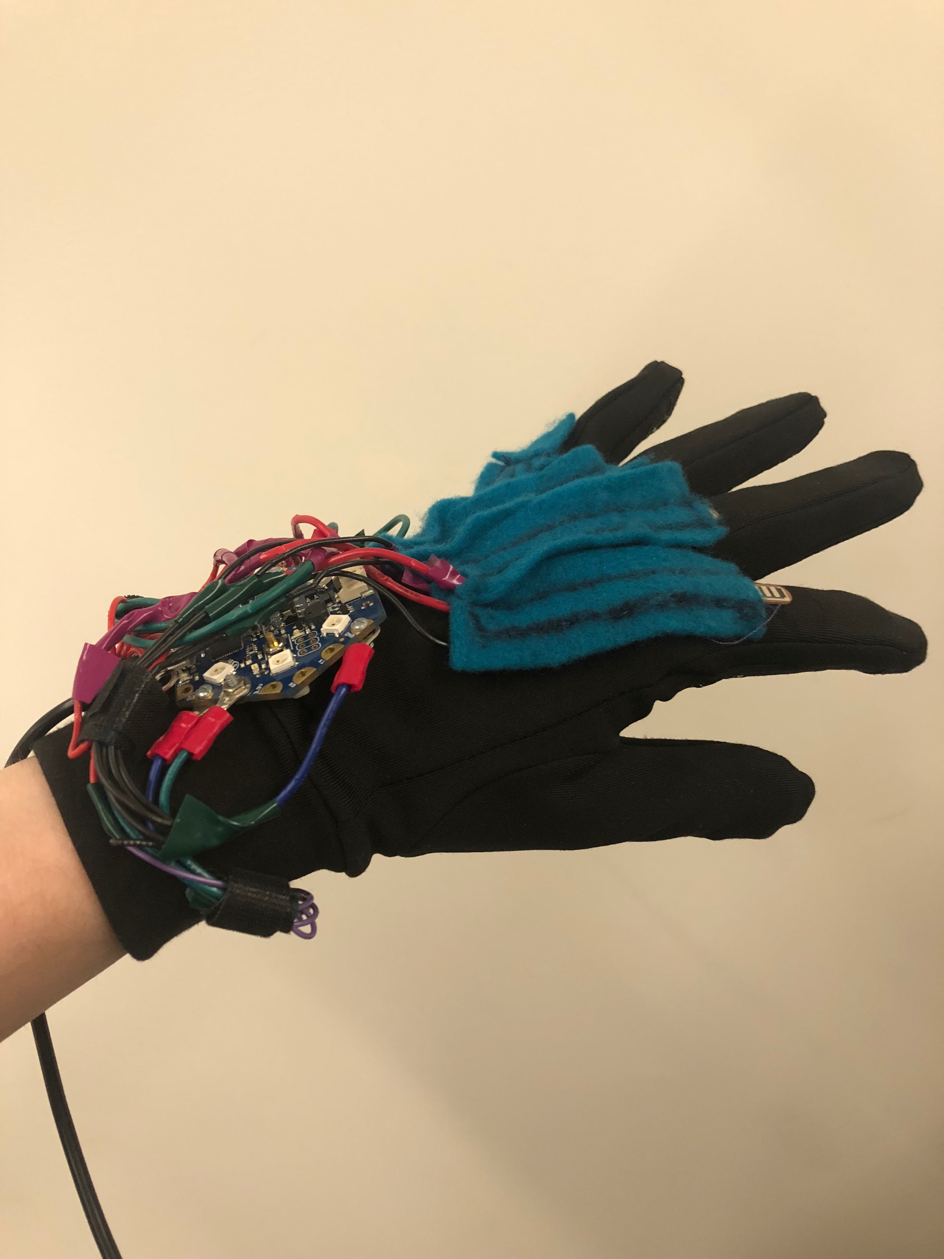
All that’s left now is to attach our circuitry to our glove. Take your additional fabric and cut out strips slightly larger than the flex sensors. Sew the additional fabric to the finger of the glove where the knuckle bends, leaving a sort of sleeve for the flex sensor to sit in (we can’t just glue the flex sensors directly to the glove because the glove fabric stretches as the fingers bend). Once the sleeve is mostly sewn, slide the flex sensor in, and carefully sew the leads to the glove, fixing the flex sensor in place. Repeat this for each flex sensor.
Next, use the self-adhesive safety pin to attach the Hex to the back of the glove (you might want to put some hot glue on the pin to make sure it doesn’t come undone during wear). Sew the accelerometer to the wrist of the glove. Finally, use the magic of zip-ties to beautifully clean up any unsightly wires.
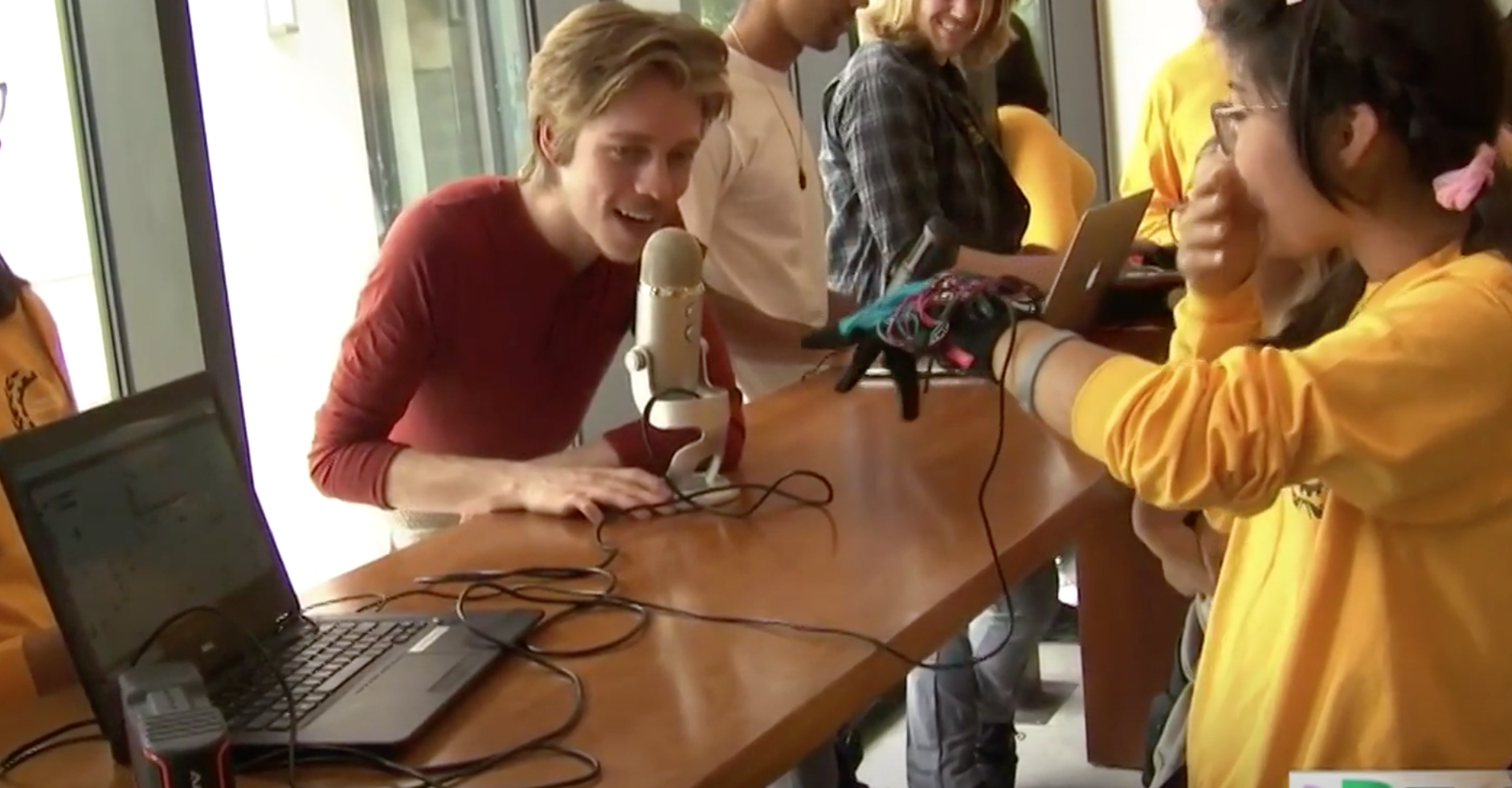
You’re ready to put your ultimate singing power glove to the test! (May we highly recommend Daft Punk’s “Harder Better Faster Stronger” to fully show off your voice-changing capabilities)