Watering System With Remote Control and Clock
by CroCro in Teachers > University+
5096 Views, 58 Favorites, 0 Comments
Watering System With Remote Control and Clock
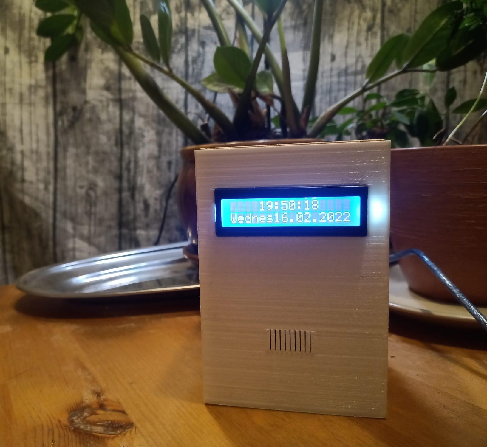
Ever had the problem with going away for a while and having to have someone come over and take care of those thirsty plants of yours? This automatic, date and time based plant watering system will take care of the problem for you, watering your plants for a desired amount of time once a day. Pump can also be switched on and off manually, using IR remote. It also features an LCD screen which displays the time and date, as well as the day of the week. This system can easily be modified to switch on something else than a pump in a timely manner.
In short: Time and date based watering system with a remote, that functions also as a digital clock.
Supplies
To get the system working, no special tools are really required, as all you really need are the proper components, functioning code and attention to detail to get the wiring right. If you are planning on using the 3D printed container seen here, you do need some basic tools. I've also left all the connections on to a breadboard in order to use them in other projects, however it is also possible to make your own circuit board, for which you will need the additional required tools, such as a soldering iron.
Tools required:
Small flatheaded screwdriver
(Optionally)
Multimeter
3D printer
Laser cutter/engraver
Hot glue gun
Wire stripper (optionally, you can use scissors to peel the wires.)
Materials required:
Arduino UNO (The one used in this tutorial comes from ELEGOO super starter kit)
2x16 LCD display (No I2C. The one used in this tutorial comes from ELEGOO super starter kit)
1838 IR receiver module (The one used in this tutorial comes from ELEGOO super starter kit)
10k Potentiometer (The one used in this tutorial comes from ELEGOO super starter kit)
12V 4.8W Water pump (You should not run this pump while dry)
IR remote (The one used in this tutorial comes from ELEGOO super starter kit)
A decent amount of jumper wires for all the connections
A small breadboard (The one used in this tutorial comes from ELEGOO super starter kit)
Double sided tape
(Optionally for the casing)
Plywood for laser cutter
Filament for the 3D printer
Additionally:
In order to water the plants, you will need a clear 8mm hose that fits your pump, as well as a pot for your plants. You will also need a water container, which can be the size of your choosing.
Wire Up the Components
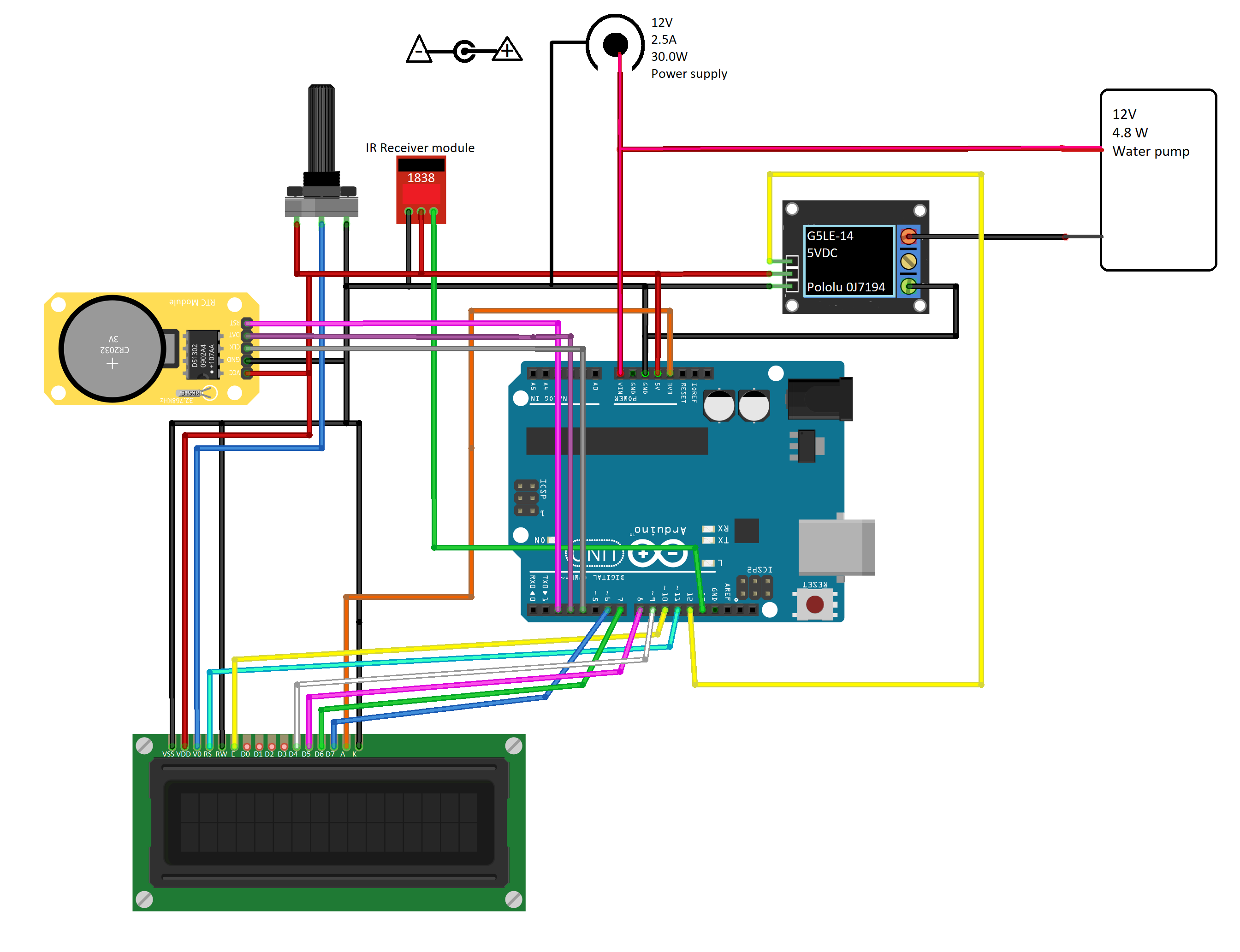
I highly recommend trying to wire up the system and test it using clear connections on a larger breadboard, before using a smaller one for a more compact system to use with the casing. (I used the mini breadboard that came with the ELEGOO super starter kit). Remember that when you are working with any project that includes electricity you should take required precautions. Don't experiment if you don't know what you are doing, ask first!
First, you should wire all the components together according to the wiring diagram. This system is completely powered by the 12V power supply. Note here that the A-pin on the LCD can also be powered from the 5v Arduino pin.
Next we will go trough the connections in more detail. I will disclose the purpose of each pin on the LCD so that you get a better understanding what is what. Remember that datasheets are available online for each module and component in case you need further information.
LCD screen:
VSS ➔ GND (Ground pin of LCD)
VDD ➔ 5V (Supply voltage pin of LCD)
VO ➔ 5V through Potentiometer, refer to wiring diagram (Control pin, LCD contrast)
RS ➔ D11 (Register select)
RW ➔ GND (Read/Write pin)
E ➔ D10 (Enable pin)
D0
D1
D2
D3
D4 ➔ D9 (Data pin)
D5 ➔ D8 (Data pin)
D6 ➔ D7 (Data pin)
D7 ➔ D6 (Data pin)
A ➔ 3V or 5V (Led Positive)
K ➔ GND (Led Negative)
1302 RTC Module
VCC ➔ 5V
GND ➔ GND
CLK ➔ D4
DAT ➔ D3
RST ➔ D2
5VDC 10A Relay module
END ➔ D12
VOD ➔ 5V
GND ➔ GND
-
NO ➔ Water pumps GND wire
NC ➔
COM ➔ GND
1838 IR receiver module
G ➔ GND
R ➔ 5V
Y ➔ D13
Potentiometer, pump and power supply
Follow the wiring diagram to properly set up the power supply and pump. The pump linked in the material list comes with a connector that directly fits to the power supply. You will need to cut this off, as this connector will be used to power the system (leave about 10cm of wire from the connector). After peeling the two wires inside this connector wire, connect the positive wire to the pump and the VIN-pin of the Arduino and the negative to the GND. From the pump end, connect the positive to the connector as mentioned before and negative to the NO(Normally Open)-pin of the relay. Now you can plug in the power supply to this connector to power the pump as well as the rest of the system.
You can use a multimeter to make sure that you are using the right wires by connecting the power supply and measuring the voltage from each wire. If you decide to do this, make sure that the wires do not touch each other. For the pump in question, the wires were colour coded correctly, red being positive and black being negative wire.
Potentiometer will be connected to the 5V, GND and the VO-pin of the LCD in order to control the screen contrast.
Lets Begin With the Code
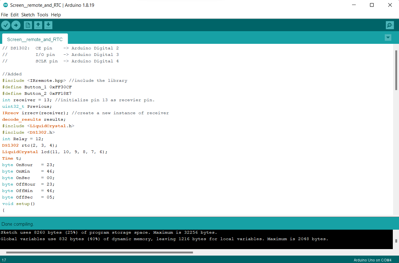
Now it's time to connect your Arduino to your pc and launch the program. I've included the code file below. There are some changes you will need to make before you verify and upload the code in order for it to work! I've included the file here.
This is what your code is supposed to look like as you open it up in your Arduino. You don't need to know how everything works, but it should be noted that lines with "//" before them are only comments made by the writer, meaning they won't affect the code, but are either there to make it easier to detect certain parts of the code, give instruction or to remember what is the function of a line. Remember this, as you will need to use this function later on.
Downloads
Preparation

Make sure you have the required libraries.
If you don't have the libraries, you will need to manually search for them and install them. You can do this from: "sketch -> include libraries -> add .ZIP library"
Define your board.
Go to tools and make sure your board is defined as Arduino UNO.
Define your IR remote buttons
You will see the following in the beginning of the code:
#define Button_1 0xFF30CF
#define Button_2 0xFF18E7
These two lines refer to the button 1 and 2 in my IR remote, which I use to switch the pump on and off. Number one has been set to switch the pump on and number 2 to switch it off. The hex code for your buttons might differ, which will require you to do some tweaking.
For instance, the hex code for my Button_1 is "0xFF30CF". If you don't know the hex codes, you can easily find out by uploading this code to your Arduino board and launching serial monitor from: "Tools -> Serial monitor" The code has been set up so that it will display the hex codes in the serial monitor as the IR receiver receives a signal. (It will also be displaying the information from the RTC, but don't worry about that yet) So once you press a button on your remote, the corresponding code will now appear in the serial monitor. This way you can use a button of your choosing to switch the pump off and on, by simply changing the hex code to the one you want to use.
Set the watering time and duration
You will also see the following quite early in the code:
byte OnHour = 23;
byte OnMin = 46;
byte OnSec = 00;
byte OffHour = 23;
byte OffMin = 46;
byte OffSec = 05;
These values are used to define when the relay will be switched on and off. In this example, the pump would switch on at 23:46:00 and switch off after 5 seconds in 23:46:05.
Switch these values to the desired values for your daily watering needs! You can always return to this part to easily change your water time.
Set the time and date for your RTC
In order to have the system function in a desired way, you will need to set the correct time and date for your RTC (Real time clock).
This is done by modifying the following part of the code:
rtc.setDOW(WEDNESDAY); // Set Day-of-Week to FRIDAY (example)
rtc.setTime(12, 00, 00); // Set the time to 12:00:00 (24hr format)
rtc.setDate(02, 02, 2022); // Set the date to month, day, year
Set the right time and date, adding a few minutes to give you time to upload the code at the right time. For instance, if it is 11:30, set the time to 11:32:00. Now you have 2 minutes of time to verify the code and make sure everything is okay.
Upload the code once the time is right. In my example, you would do this exactly at 11:32.
You're not done yet!
Now you will need to comment the lines mentioned previously. You can do this by highlighting the lines, right clicking and choosing the comment/uncomment option. Once you have done this, the lines should look like this:
// rtc.setDOW(WEDNESDAY); // Set Day-of-Week to FRIDAY (example)
// rtc.setTime(11, 19, 00); // Set the time to 12:00:00 (24hr format)
// rtc.setDate(02, 02, 2022); // Set the date to month, day, year
Now you will need to reupload your code to your Arduino. Now the first value you added will be stored in the RTC and it wont be reset every time you make changes, or restart your Arduino. The small battery in your RTC will make sure that it can keep the time even when the device is unplugged, so that it will display the right time as soon as you plug it in again.
If you ever need to change the time again, uncomment this section, set the time, upload, comment again and reupload.
Test Your System!
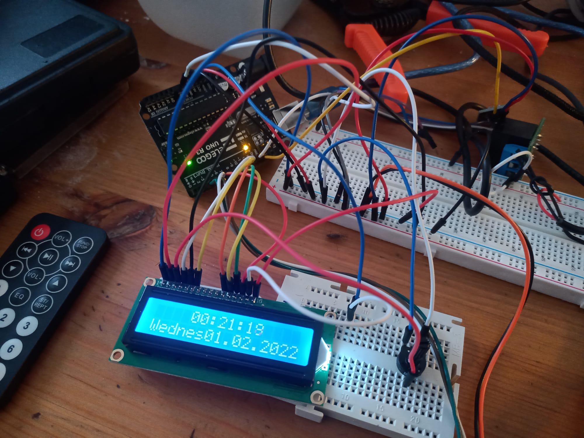
Congratulations! If everything is done correctly, you should now be able to see the time and date on your LCD screen. You can adjust the contrast of the screen with the potentiometer. You could also set your pump in water (if submersible!) and test if you can switch it on and off with the remote. (make sure that if you do this, you keep the water and pump far away from the rest of your components)
You can also mess with the code to test if the timed relay works correctly, by setting the time and the watering time just a minute apart and waiting.
Now you can choose to either build your own case, or proceed with my 3D printed casing.
3D Printing the Case
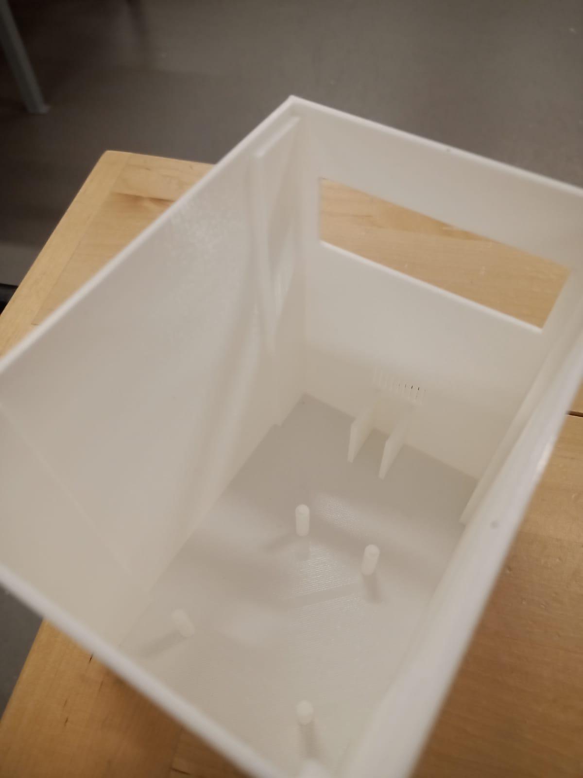
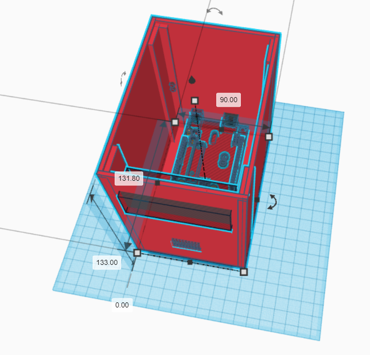
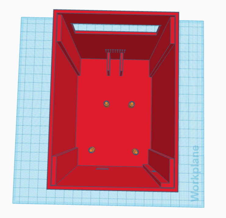
I have included the 3D file for the casing here. There were some modifications I had to do to the original one, like strengthen the supports for the Arduino UNO board.
Bring this file to a program that is suitable for editing it for your 3D printer. I was using Cura and Ultimaker 3.
In my case, after editing, I simply placed the file on to a memory stick and moved it to the printer. I used white PLA filament for this. With the settings I chose, it took about 15 hours to print.
The top part has been designed to be sealed with 3mm thick plywood. If you have a laser cutter available, easiest way to do this is to draw an appropriate sized rectangle with a vector tool, such as Inkscape, bring it to the laser printer and modify the settings accordingly. It is better for me not to give exact instructions to this, as the required functions of each laser cutter is different and by following instructions that worked with mine, you might break yours. So make sure to operate the one available to you correctly!
You can also simply cut the piece by hand.
Downloads
Move the System Into the Housing
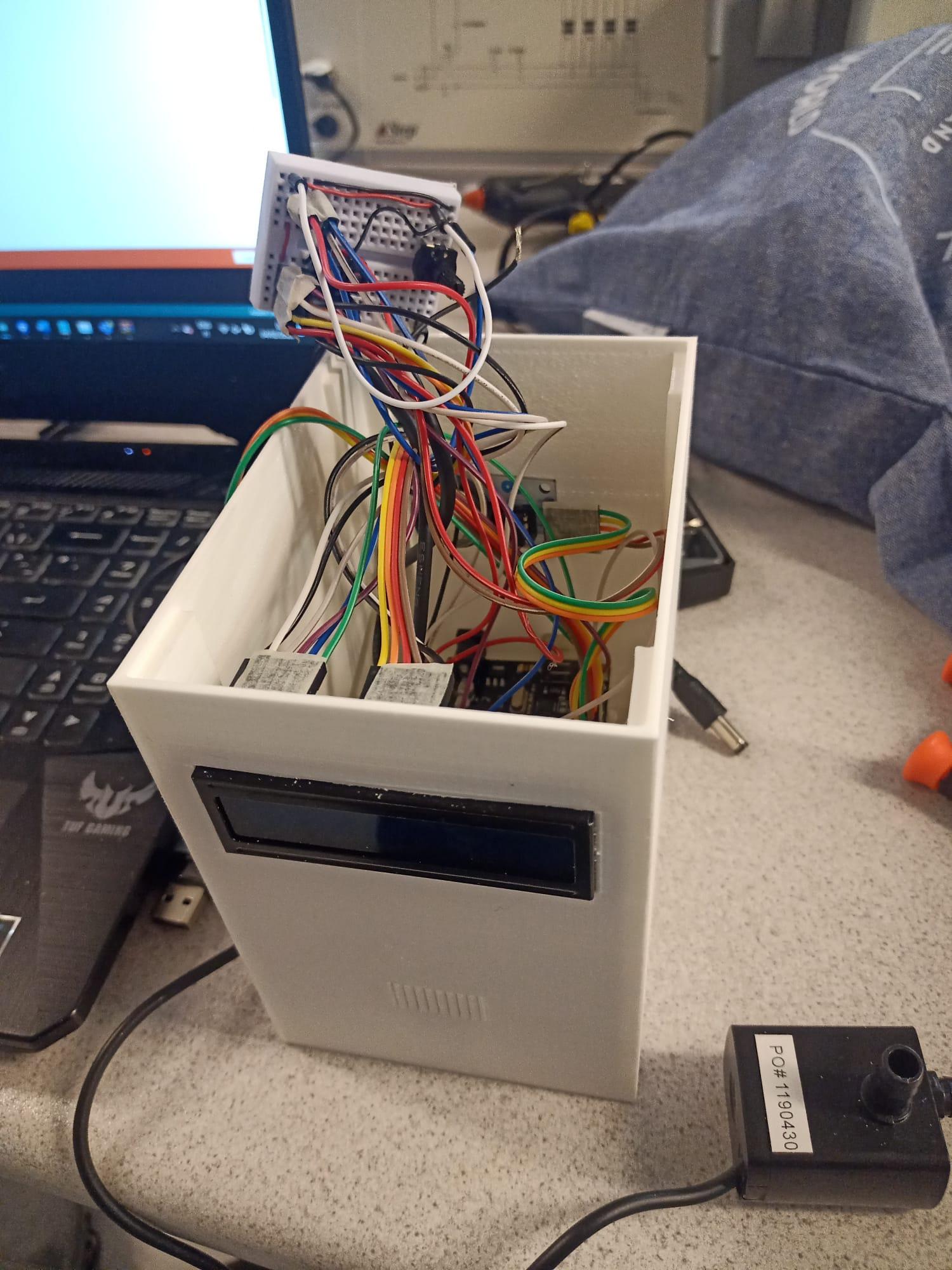
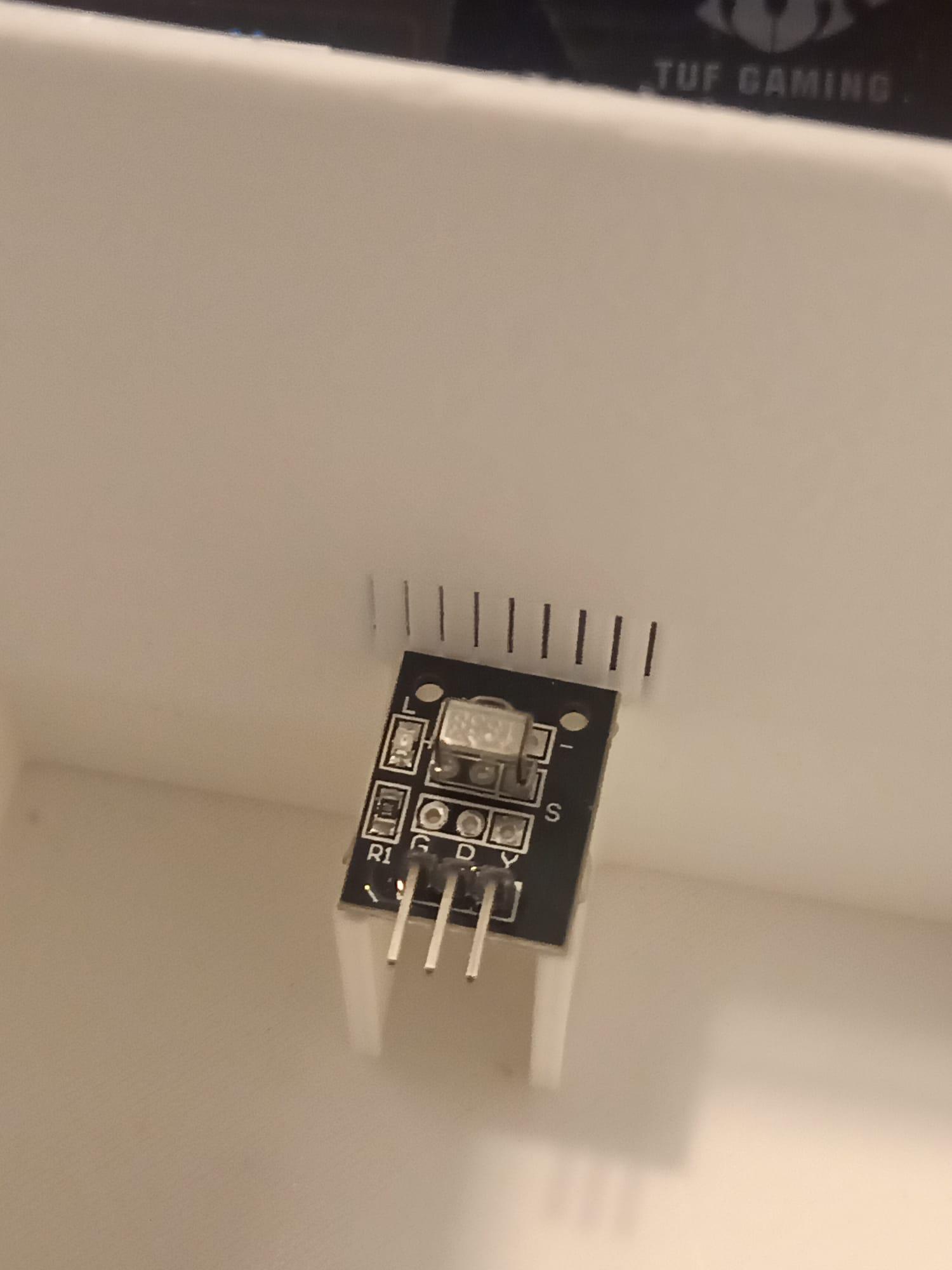
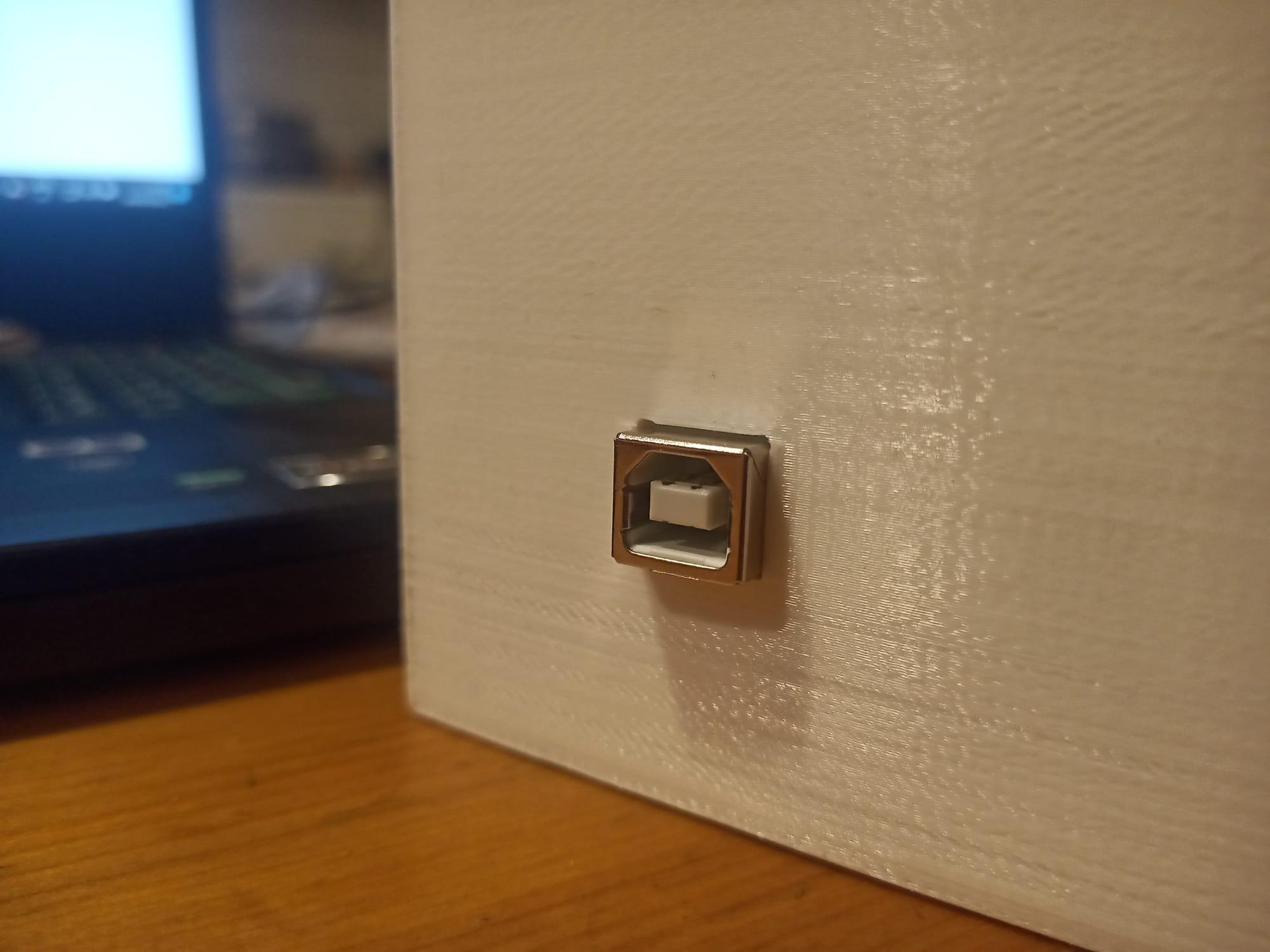
Be very careful doing this, especially if you are using a breadboard, as it is a tight space.
Install the Arduino UNO
Make sure that the USB connector will line up with the hole in the case. I simply used hot glue to attach the board.
Install the LCD and IR receiver
Start from the receiver. It has it's place behind the grid below the screen, which allows it to receive the IR signal. Again, I used hot glue to install it. Screen should fit on its place tightly.
Install the breadboard
I used two sided tape to stick the breadboard in the inner wall of the container.
Install the power connector and pump wire
You will need to disconnect these from the relay and Arduino UNO before doing this. Thread them trough the holes in the back of the casing and re-attach them to the relay and Arduino board. After this you can use double sided tape to attach the relay on the side of the container as well.
Seal the container and plug in the power supply!
You're done! Congratulations! You can now plug in the device and place the pump however you want it. You can connect two clear hoses to it, running other to your water reservoir and other to the plant. Just make sure you know which end is which.
Modify!
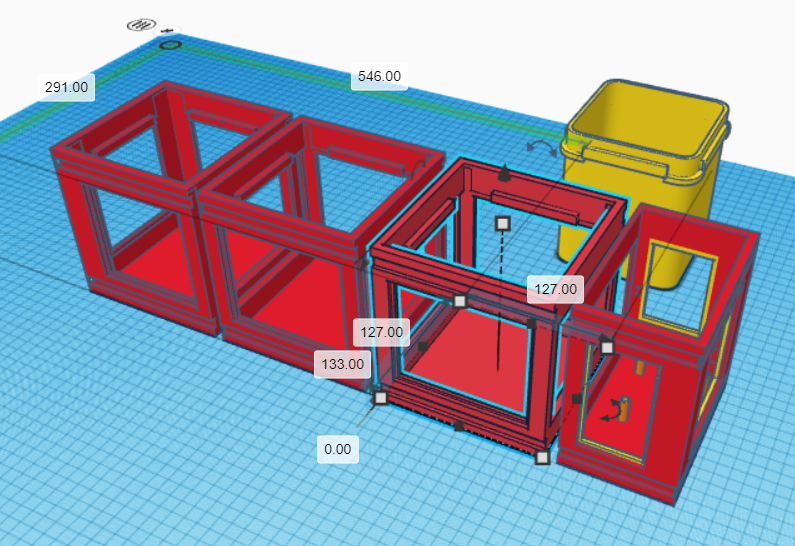
You can power something else!
Maybe you could design a different case?
Maybe you want a more permanent attachments for your module and components?
Above I've included additional 3D file where I've made 3 holders for simple plastic flower pots. Each case is covered with plywood panels, while the system has it's own case on the side. This version does not include the LCD screen and is purely a watering system, but you could always add one. Go ahead and modify this as well, if it gives you some ideas!
Making changes and figuring out how to do something that you want to do, is the best way to learn!