Watering Indoor Plants With NodeMCU, Local Blynk Server and Blynk Apk, Adjustable Set Point
by cristeaflorin71 in Circuits > Arduino
1109 Views, 3 Favorites, 0 Comments
Watering Indoor Plants With NodeMCU, Local Blynk Server and Blynk Apk, Adjustable Set Point
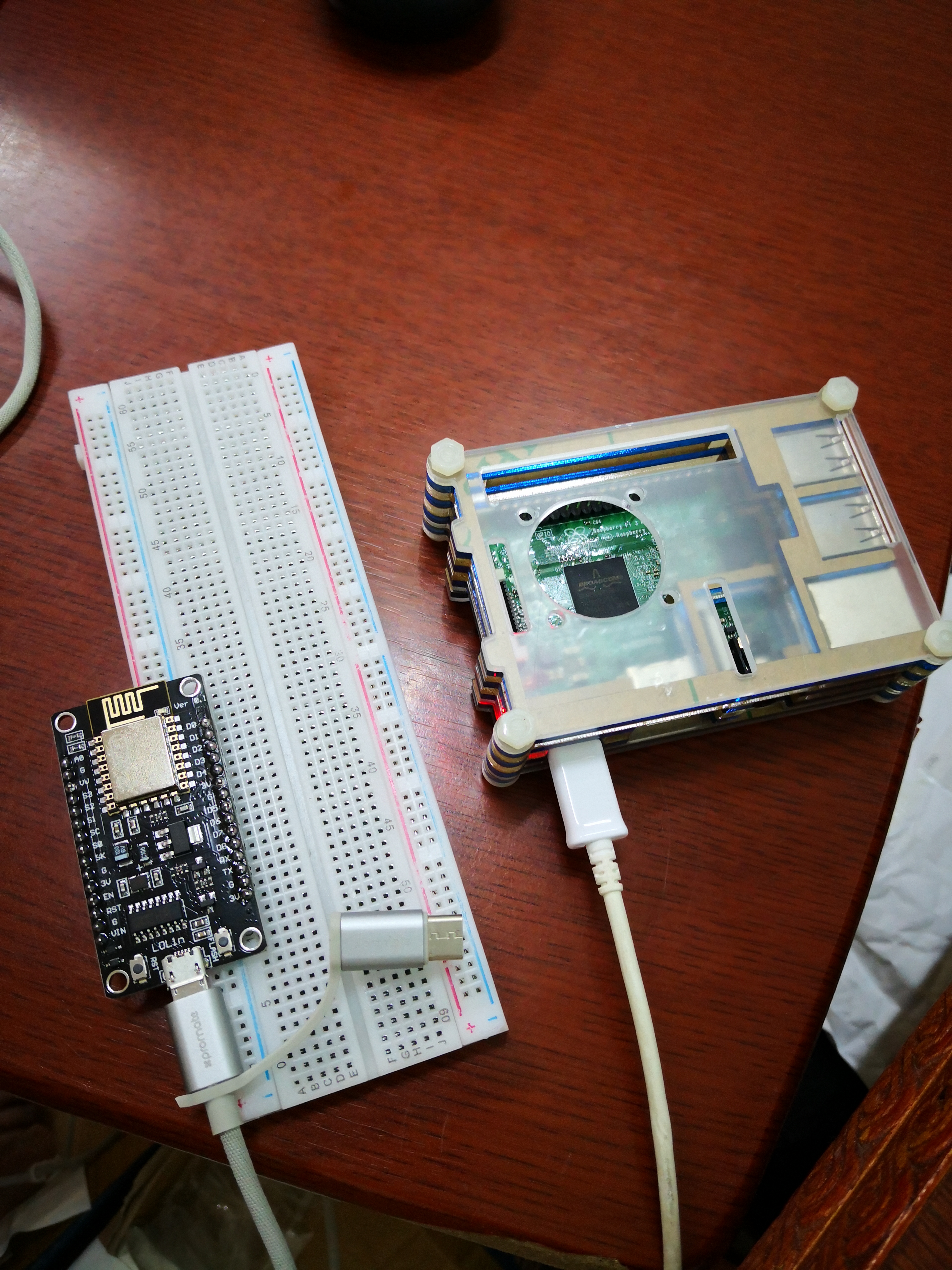
I've build this project because my indoor plants needs to be healthy even when I am in vacation for an extended period of time and I like the idea to have control or at least monitor all the possible things that happens in my home over the internet.
Supplies
NodeMCU ESP-8266
Raspberry Pi 3
SD card (16Gb recommended)
Capacitive Soil Humidity Sensor (or DIY)
3-6 V (DC) Mini pump
2N2222 or equivalent NPN transistor
1x 1N4148 diode
1x 1K resistor 0.25W
Breadboard or Prototyping board
Jump wires
Prepare You Local Blynk Server

The software core of this project is Blynk IOT platform. They are offering free hosting for small projects with possibility to buy extra credits if you are planning to extend your ideas. The good part of this platform consist in possibility to install locally their Java based server on a variety of platforms including Windows or Raspberry Pi3, which I am going to use in this tutorial.
First of all, you have to install the latest available Raspbian build, Buster is the version I am using at the moment. For instructions, details and settings, a good tutorial is this.
Obviously, is mandatory to connect your RPi3 to your router via LAN or WiFi. Even if you don't have a keyboard or monitor to connect to your RPi3, you can connect it to your WiFi with help from this tutorial.
Now, the Blynk server installation on your freshly installed Raspbian can be done very easy following this tutorial. I have to tell you that you have to replace some of the instructions from it because since that tutorial was written, Blynk server got some updates and you have to update accordingly. So, when they ask you to download the server, you have to replace the command wget "https://github.com/blynkkk/blynk-server/releases/download/v0.23.0/server-0.23.0.jar" with wget "https://github.com/blynkkk/blynk-server/releases/download/v0.41.8/server-0.41.8-java8.jar"
Because the Blynk server will not start automatically after RPi reboots, you have to add in Crontab file as they instructed by adding at the end of it, the following line :
@reboot java -jar /home/pi/server-0.41.8-java8.jar -dataFolder /home/pi/Blynk &
The last mention regarding the installation of Blynk server is that the page you will access for administration purposes will be https://IP_BLINK_SERVER:9443/admin and you have to pay attention for the port number, 9443, because in that tutorial, at that time, the port used was 7443
For the server to be accessible from internet, you will have to forward port 9443 to the internal Blynk server IP address and also you have to use a DDNS service in case the public IP address will change during router reboot. If you are the owner of ASUS or Mikrotik routers( I am giving these examples because i have both brands and I am using successfully their DDNS service), or any other brand with their own DDNS service, things will be much easier for you.
Hardware Setup
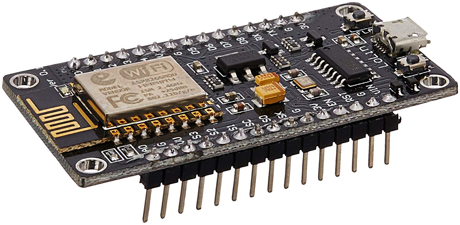
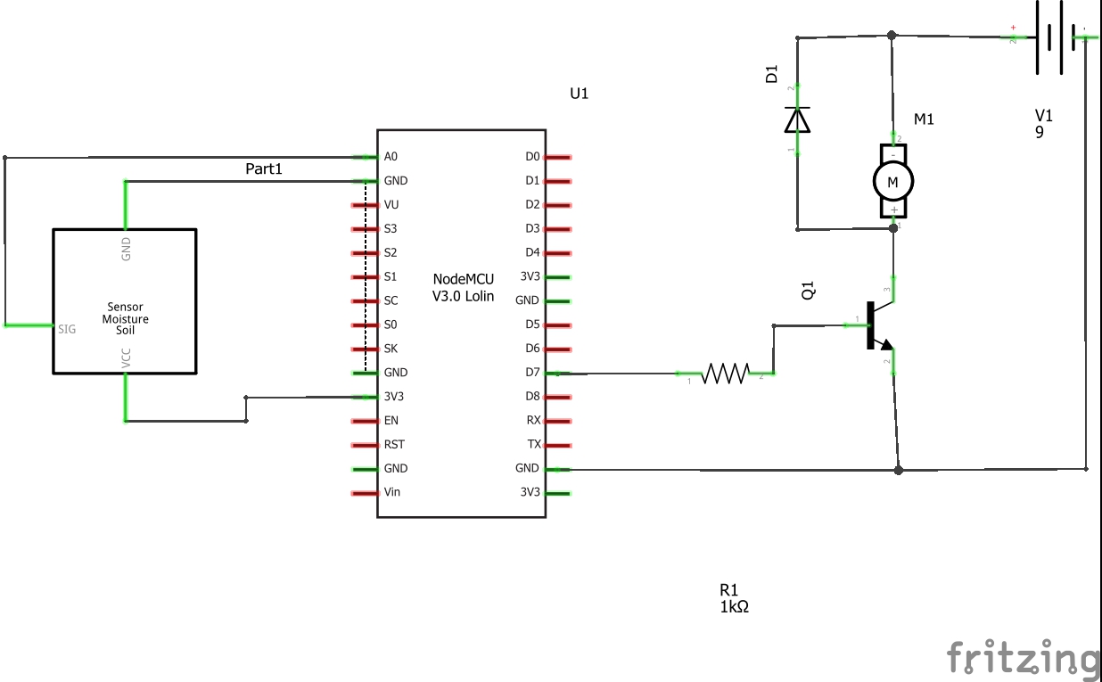
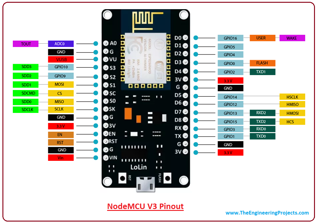
As for the hardware, the interfacing module between sensor, pump and Blynk server, I chose NodeMCU ESP8266. This module is equipped with ESP8266 chipset for WiFi (which is very well documented and included in lot of IoT projects). If you want to experiment further, you can choose the simplest version, ESP8266 ESP-01, as long as this projects needs only 2 pins to work: one Analog input to read the values from Soil humidity sensor and one output to start the pump for watering.
But in this project we will use NodeMCU because is much easier to upload the sketch( via USB cable) and is breadboard friendly, making possible future developments( as adding an LCD for example to read actual humidity and set point or adding a relay to provide growing light for your plants).
As stated before, we will use one Soil humidity sensor, capacitive type. On the market you can find resistive type also, with same range of analog output values but is proven by many DIY-ers that is unstable and is not measuring the real humidity level in soil but the density of dissolved salts, ions in your soil.
For the pump part, I used a NPN transistor to drive the motor. The connections you can see in the fritzing file attached and schematics in the title picture. Note that you will need a second power supply, ranging from 7 to 9 V, with enough current to drive the pump. In my case, the measured current flowing through pump was 484mA and i used a 9 V power supply. The flywheel diode is used to remove de reverse current flowing through motor coil when this is going to stop, to prevent transistor damage.
Downloads
Coding and Setting the Blynk Application in Your Mobile
In this step you have to load the attached sketch into NodeMCU.
First of all, you have to add ESP8266 board into your Arduino IDE. This can be done very easy, following this tutorial.When you will connect NodeMCU to your computer, using an USB cable you have to check the COM port and select it accordingly from Arduino IDE.
Second, you have to add Blynk library into IDE, by following this tutorial.
And finally, you have to install into your mobile, Blynk application from Google Play.
Now, open Blynk application in your mobile and setup your account. Select custom server in the main screen and enter the DDNS name you set in Step 1 in this tutorial. Leave the default port unchanged(you already forward this port in your router earlier). In user name field put your email address and choose a password. The account will be created and now add a new project, name it as you wish.Choose NodeMCU as the board you will use and Connection - WiFi.You will receive an authentication token in your email, this code will be inserted into the sketch attached, I made it clear where you have to write it, in comment side.
After that, in Blynk application you have to add the following widgets:
LCD widget - will read pin V9 (virtual pin V9), and switch to advanced; this will show WiFi strength and IP address
Gauge widget - will read virtual pin V2, with range from 0 to 100, this will be Actual humidity in soil
Numeric Input widget - attached to virtual pin V1, range form 0 to 100, this will send the set point for humidity to an integer used in sketch
Super Chart (optional) - will read data stream from virtual pin V2 in order to create a chart with your plant humidity.
Finally, replace in sketch your authentication token received in your email, replace WiFi name and Password for WiFi and upload your sketch to NodeMCU.
I hope everything will go smoothly and without any problems as your plants needs to be healthy!
Good luck !