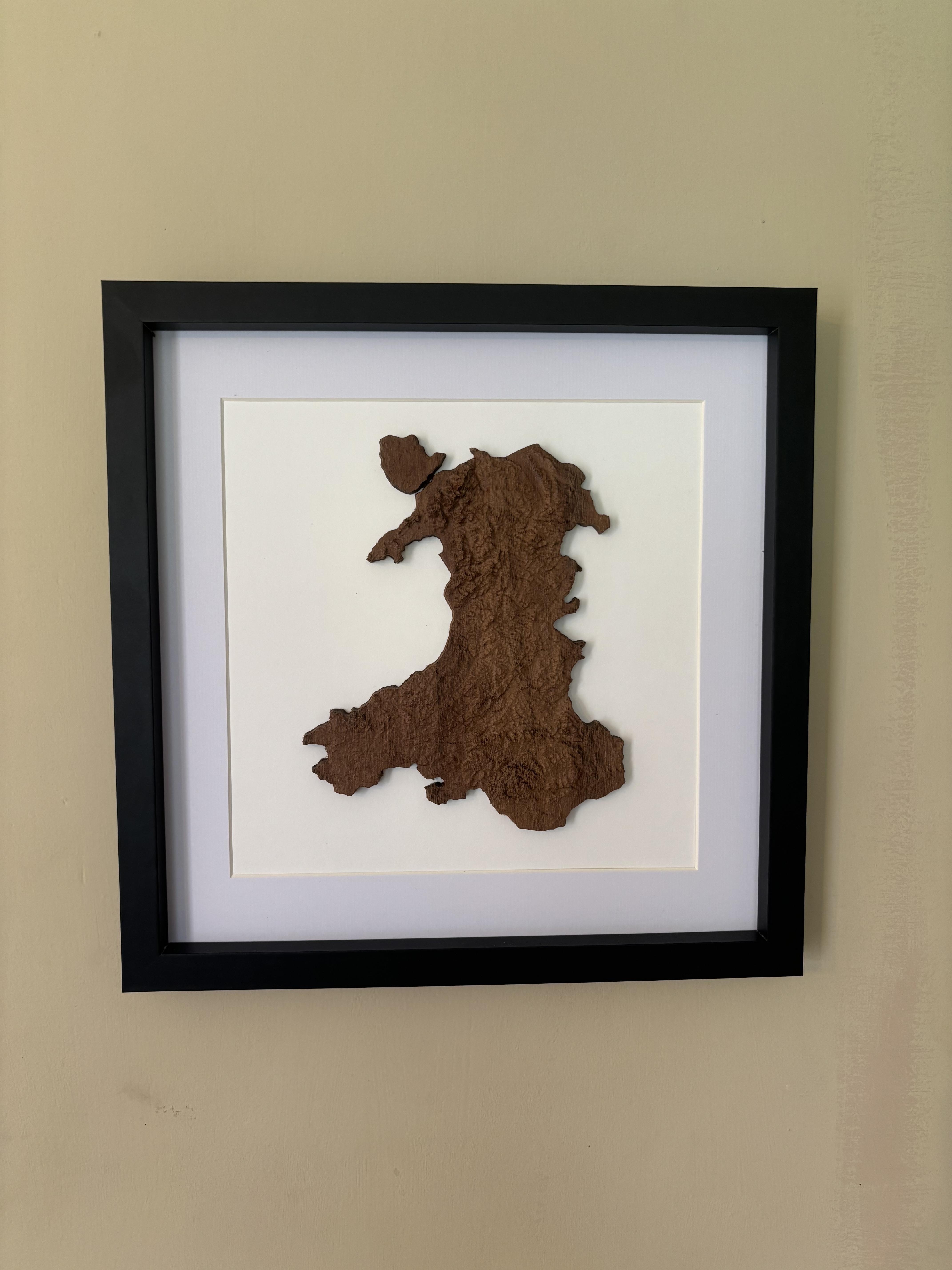
Wales Topographical Height Map
I've always loved the look of topographical maps, especially 3D relief-style ones, and given that my Mum is Welsh, I decided to make one of Wales for her.
I ended up making three maps in the end (my girlfriend and aunt, who are also both Welsh, wanted one too), and the pictures kinda jump between both.
Supplies
Material
Wood - I'm not 100% sure what species of wood I used, but I know it was quite a dark hardwood. I wouldn't recommend using a softwood for this project as I reckon it would chip too easily.
Machinery
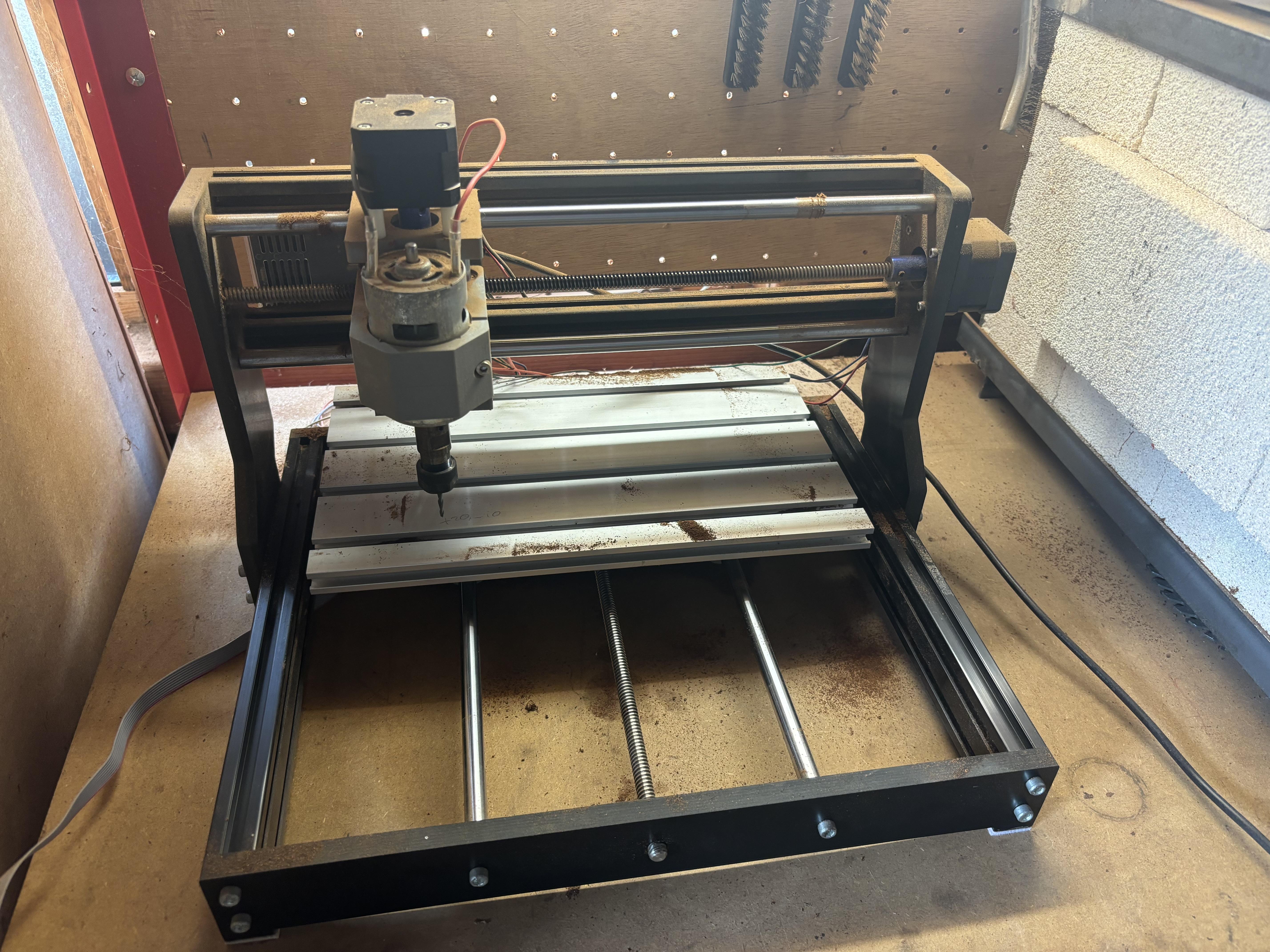
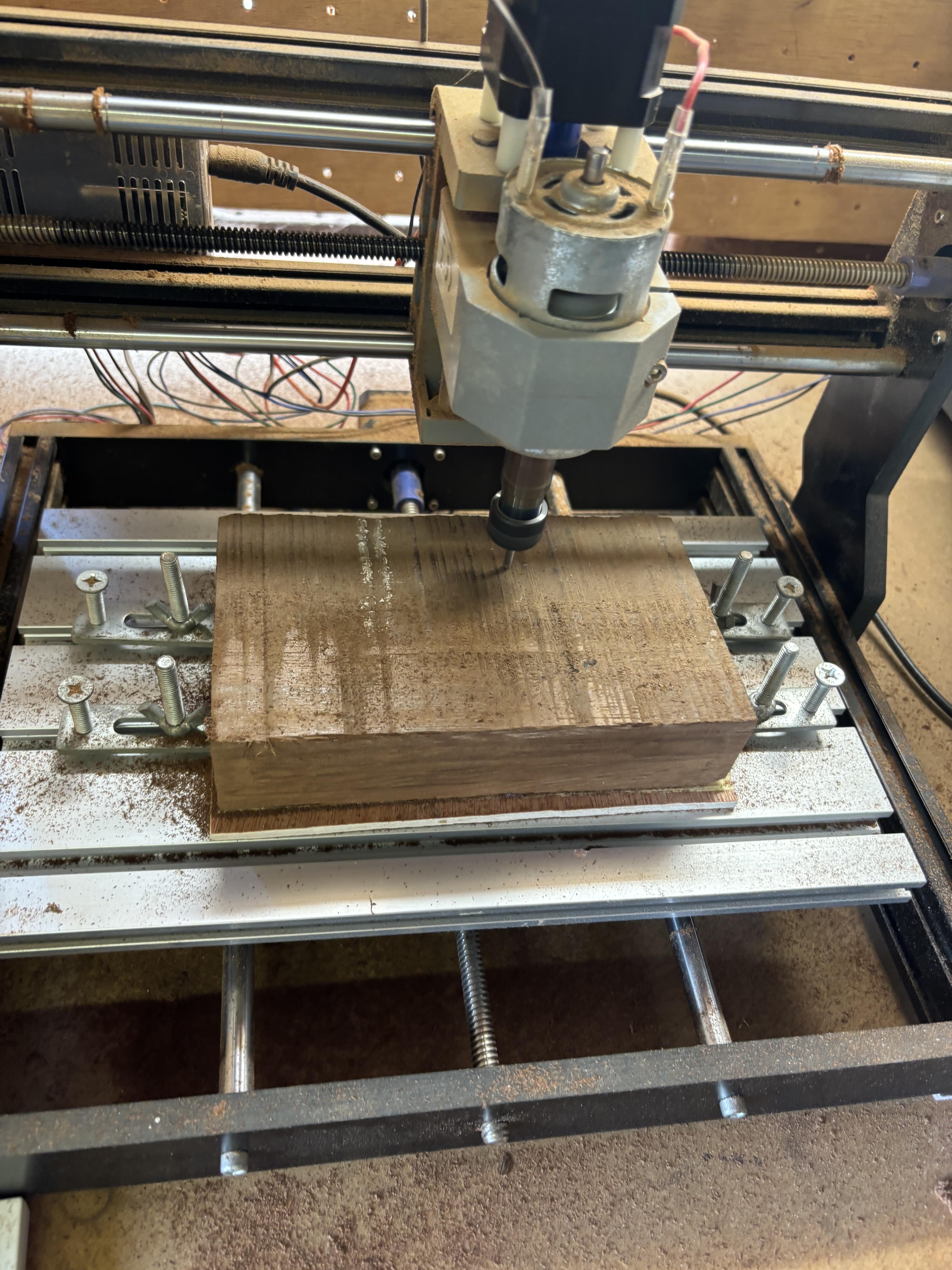
CNC - I used a 3018Pro I bought from Amazon about 5 years ago. It's not the most rigid machine, but with some fairly mild feeds and speeds, it cuts pretty well and leaves a reasonable finish.
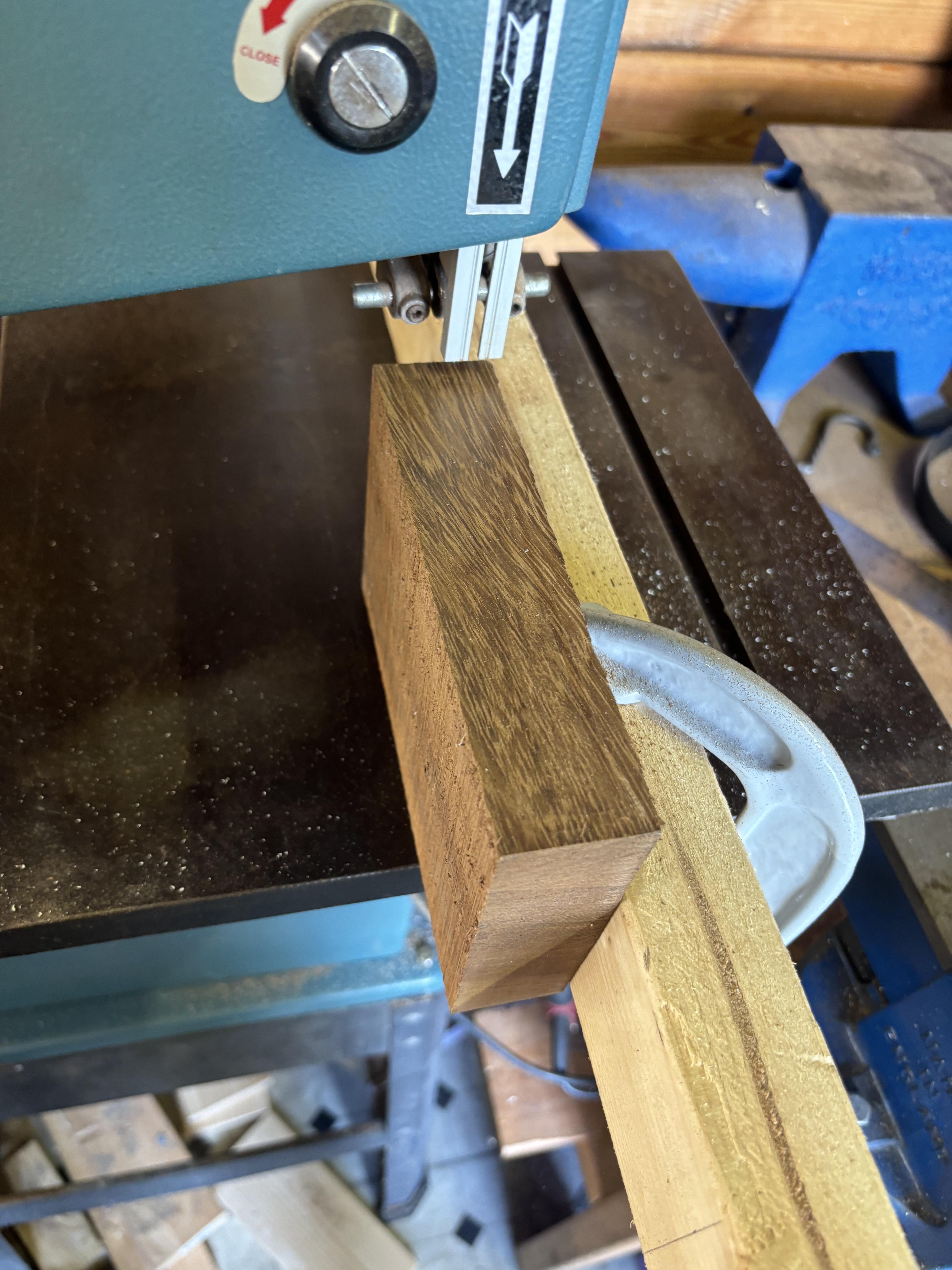
Bandsaw - This is optional, but the wood I had was quite this, about 2-3 times the thickness that I needed, so I used a 1/2" blade to resaw the material to about 12mm thick.
Tooling
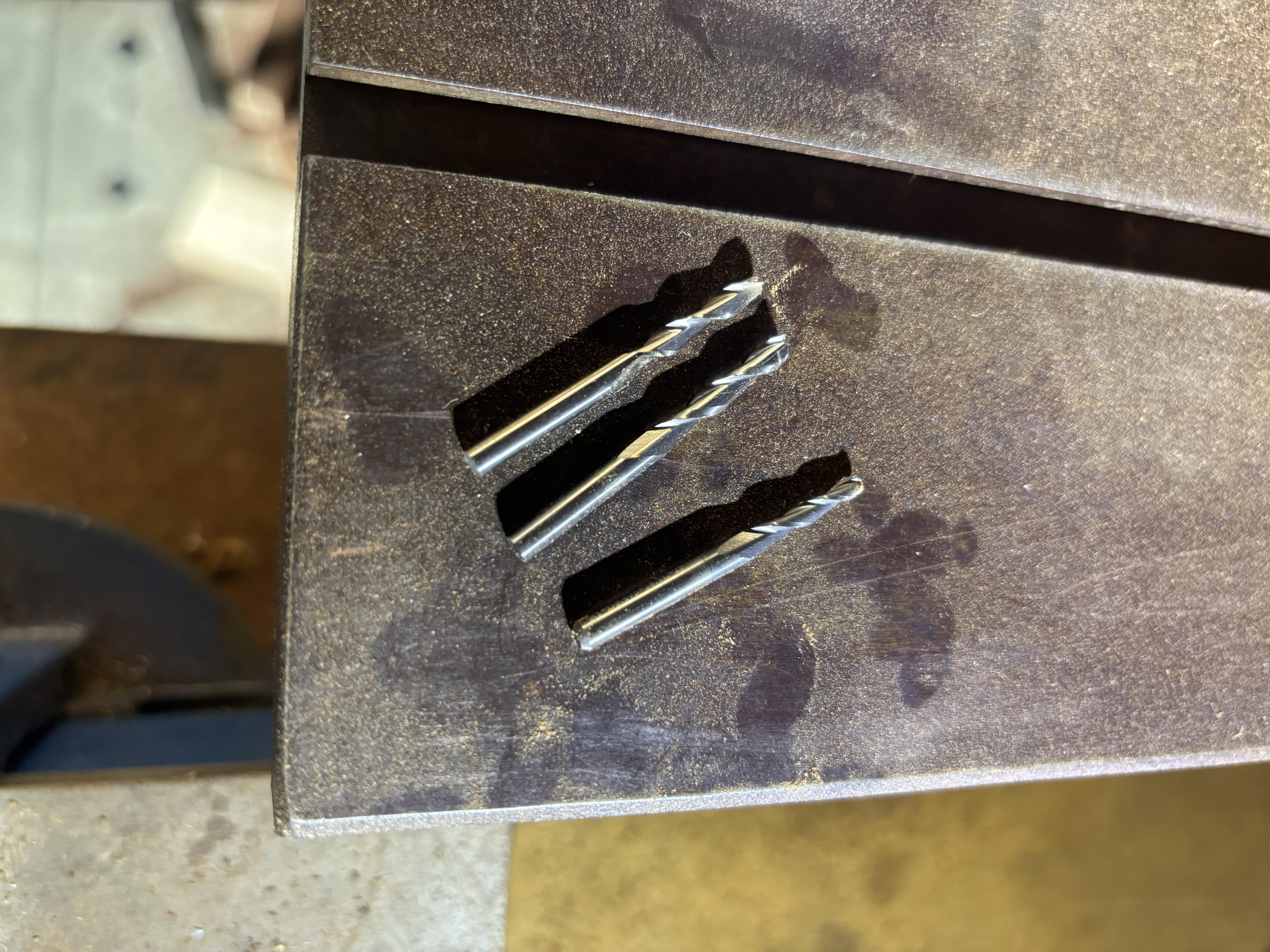
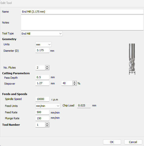
3.175mm End Mill - This was used to surface the material, to give me a flat surface to start everything from.
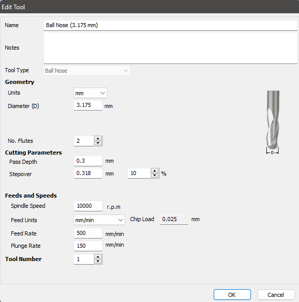
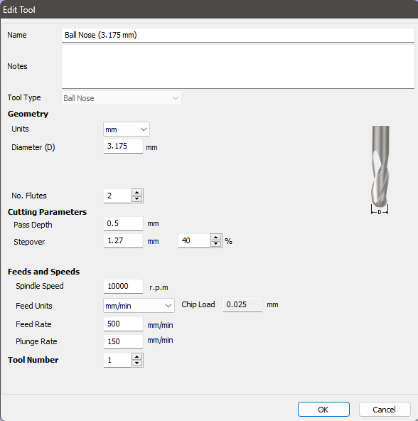
3.175mm Ball Nose End Mill - This was to rough the model's surface.
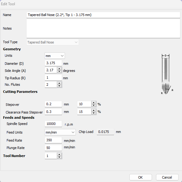
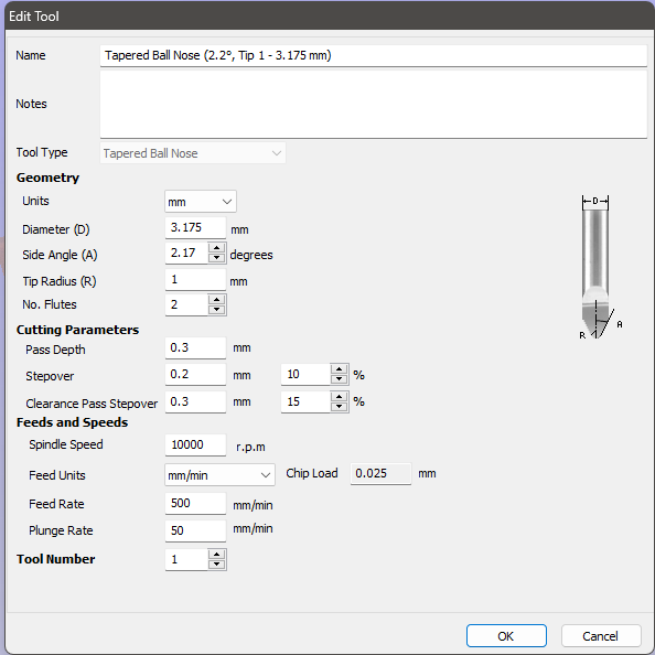
1mm Tapered Ball Nose End Mill - This was for the finish pass, you could use a finer bit, but it would take much longer and would increase the risk of snapping the bit.
Clamping
Scrap Wood/Waste Board - As I will be cutting out the country, I need to be able to cut all the way through the workpiece, and as I don't have a wasteboard on my machine, I just used a scrap piece of 3mm plywood.
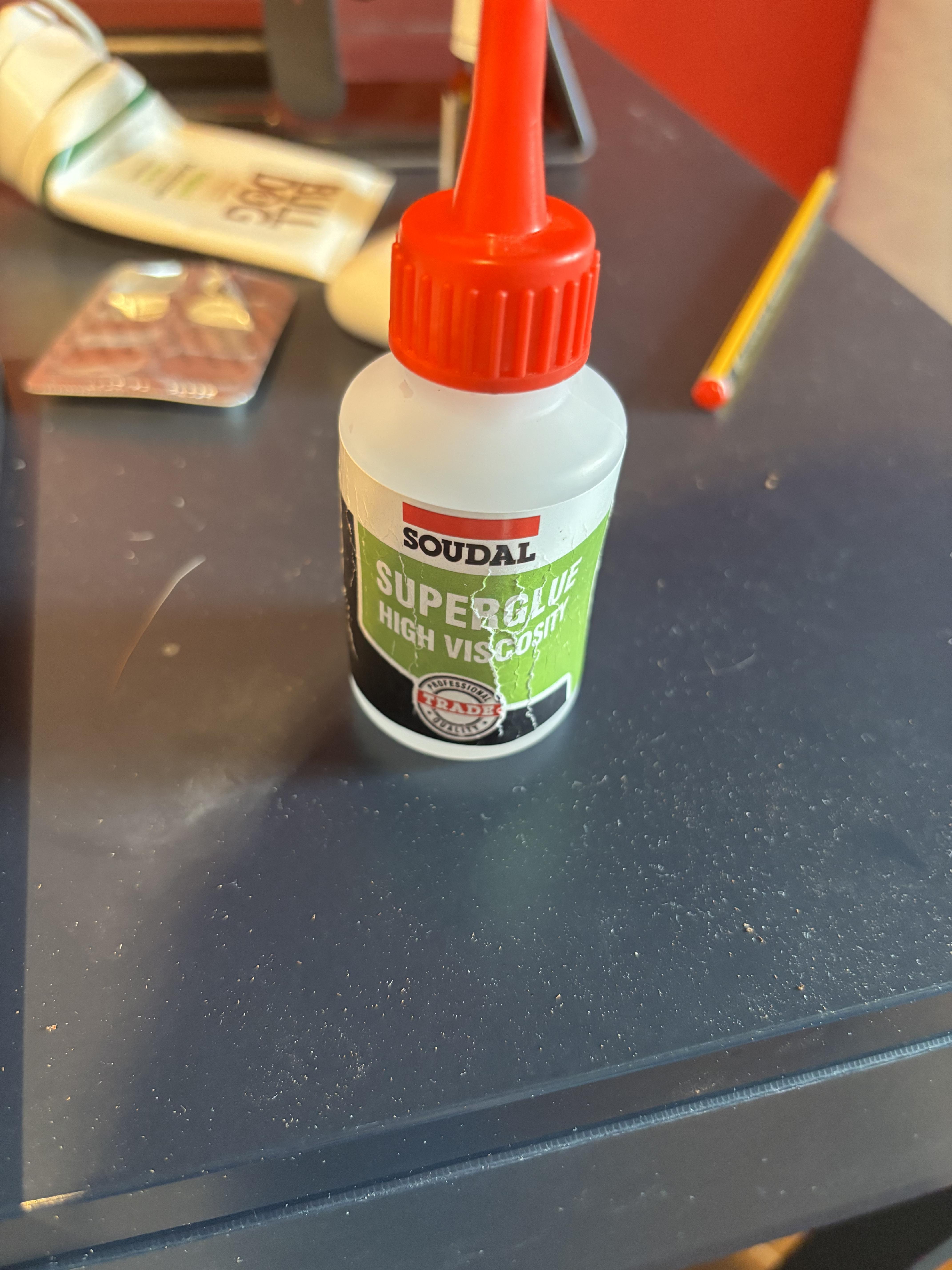
Super Glue - Because I need to access all sides of the project, clamping with normal hold-down clamps isn't really an option, so I opted to use superglue.
Masking Tape - I didn't want to mess up the underside of the map, so I stuck some masking tape to it and superglued to that.
Model Preperation
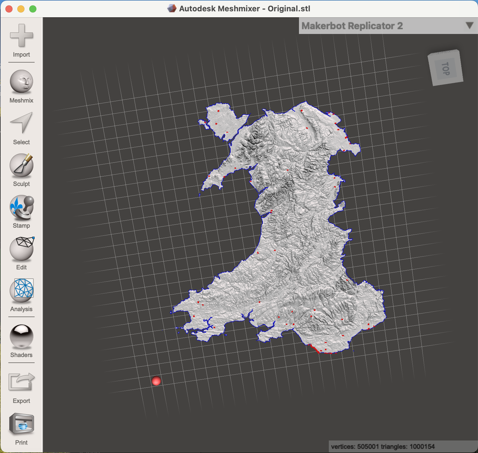
To start off, I knew I needed to find/make a 3D model of Wales. Thankfully I found this one by John Davies on Sketchfab which was exactly what I needed.
One this I noted was that all of the tiny islands surrounding the mainland were far too small to be machined, some being less than 1mm, and would almost certainly chip away during the machining process. I also realised that the gap between Anglesey Island (a relatively large island off the northeast coast) and the mainland was too small for the end mill to fit through at this scale.
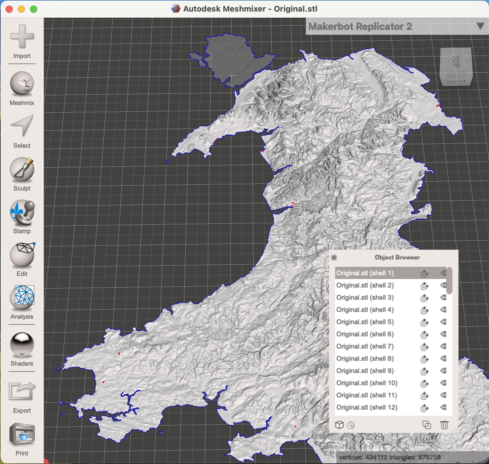
I modified the model in Autodesk Meshmixer, where I separated the bodies by going to Edit -> Separate Shells and then deleting all of the bodies, other than the mainland and Anglesey. I then exported it as an STL.
G-Code Generation
Whilst all of the toolpaths could have been done in a free software like Fusion 360, I was lucky enough to have a friend who has Vectric Aspire, so I used this to generate all my toolpaths.
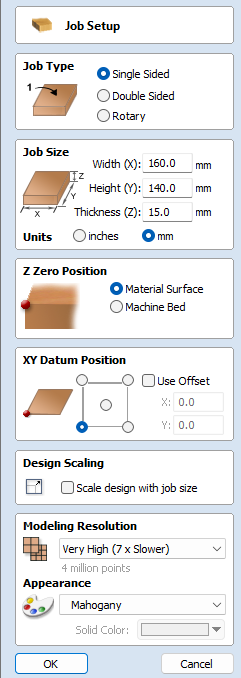
Setup
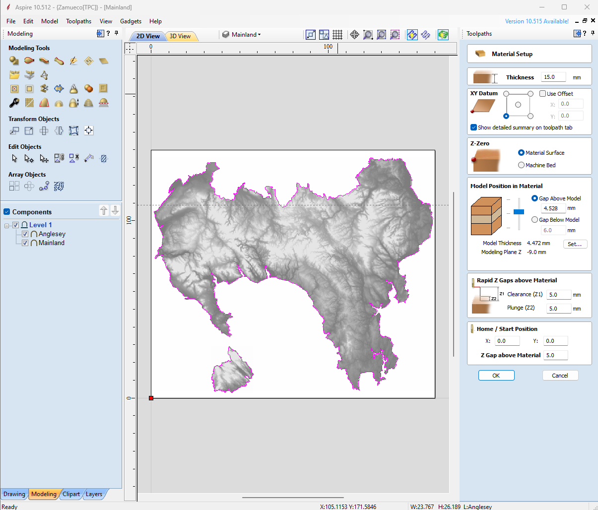
I first opened a new Aspire file, inputted my job size, and selected the 'Z Zero Position', this is either the material surface of the machine bed and is basically where the tool starts, I selected material surface as my Z Zero Position. For the XY Datum Position, I selected the bottom left, and this makes the most sense for my machine.
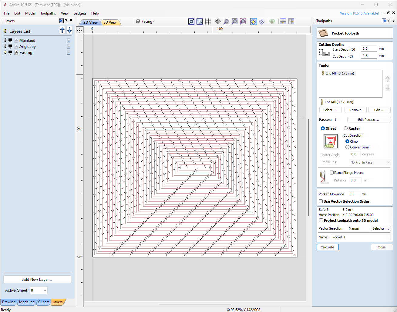
Facing
To start with I knew I needed to face the material to start with a flat surface. I draw a box the same size as the document. I then made a new layer, called 'Facing', and moved the rectangle to this layer. Then in the Toolpaths tab, make a Pocket Toolpath, and set your cut depth, I used 0.5mm, as I could always run it multiple times until the surface was smooth. I then selected the tool and set the speeds and feeds, (all the speeds and feeds are in the images). The last step for facing was selecting the vector, which is just selecting the 'Facing' layer we made earlier. Then we can just change the name and press calculate.
Model Import
I then brought the two files into the document, by going to Model -> Import Component / 3D Model and selecting the two STL files. The main thing to note when importing the model is the model's position in the material, I chose to have 6mm below the model. When the two models were in, I needed to create a boundary around each of them, so in the Modelling tab, I selected the 'Create vector boundary around selected components' and an outline was created around both bodies. I then created two new Layers, 'Anglesey' and 'Mainland' and moved the components, and their outlines into the respective layers.
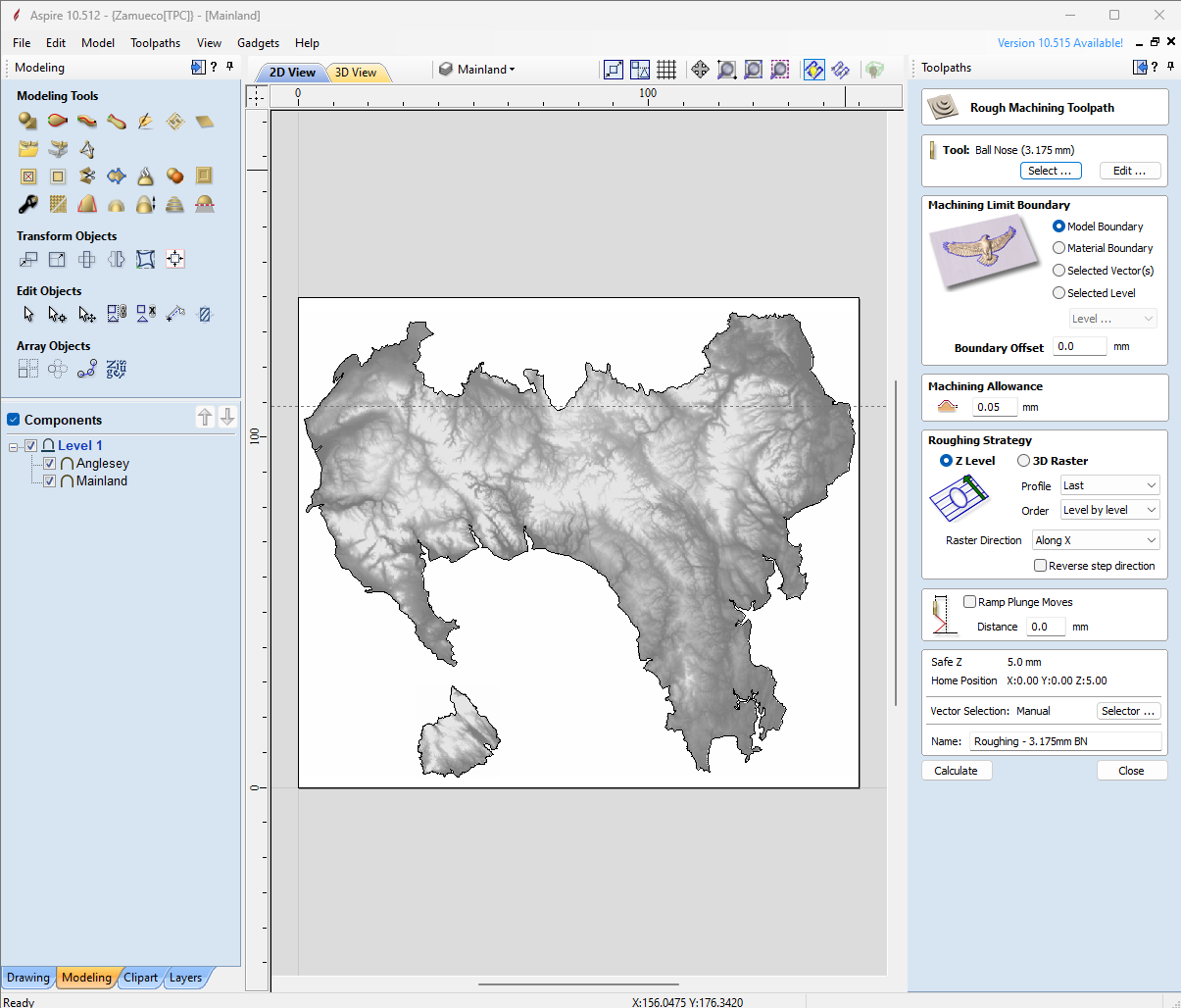
3D Roughing
Heading back into the 'Toolpaths' tab, I first created a '3D Roughing Toolpath', selecting my 3.175mm Ball Nose Endmill as the tool, choosing 'Model Boundary' as my Machining Limit, having a machining allowance of 0.1mm and selecting both the Mainland and Anglesey for the vector selection. I then renamed it and calculated it.
Profile 1
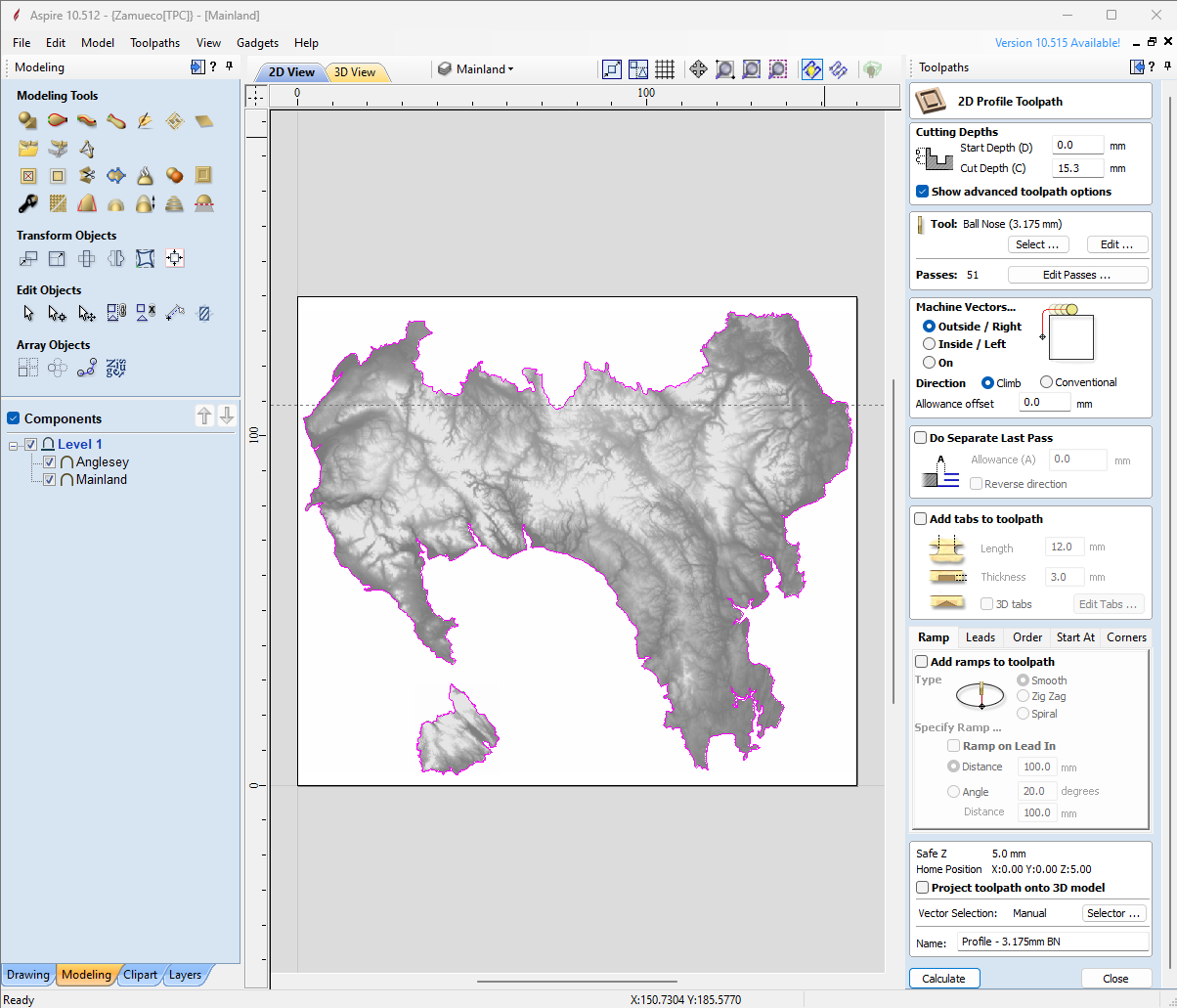
I then did the first of two profile cuts, using the same 3.175 Ball Nose End Mill. I decided to do this before the finish pass because it meant I didn't have to change the tool, and I could get rid of the bulk of the material with the larger tool.
To do this I made a new 'Profile Toolpath', selected the same 3.175mm Ball Nose End Mill, and selected the Mainland and Anglesey layers in vector selection. I was also sure to make sure it was cutting on the outside of the lines. I did make sure to change the cut depth to about 0.5mm deeper than my material, just to make sure it would definitely go all the way through, and that the radius of the bullnose wouldn't leave a cusp around the edge. This is why we need a wasteboard or a piece of scrap under our workpiece.
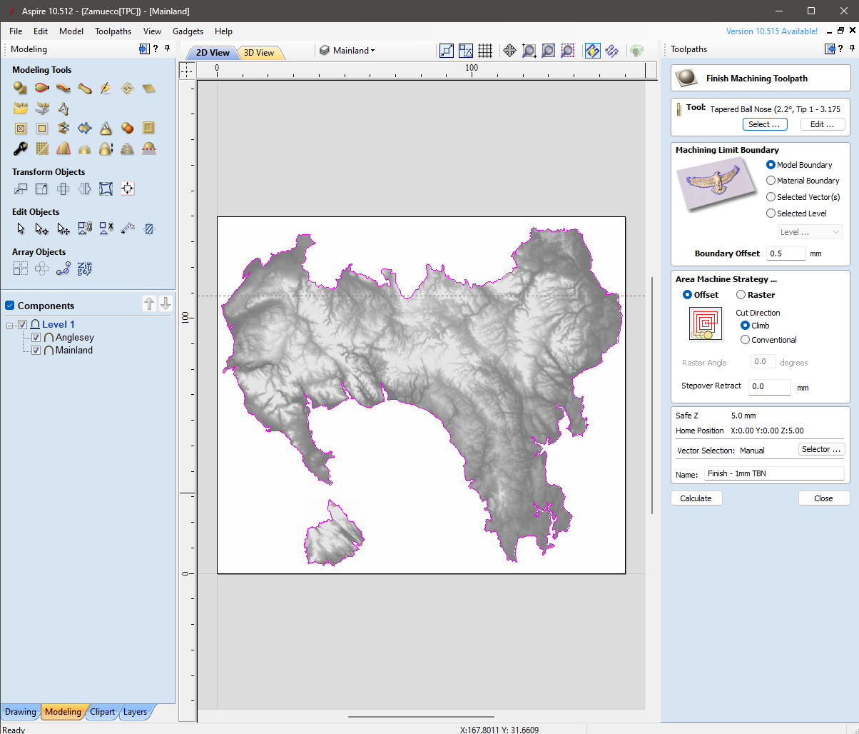
3D Finish
The finish pass used a 1mm Tapered Ball Nose Endmill. I selected the 3D Finishing Toolpath, and the 1mm TBN Endmill, and then set the stepover of the tool at 10%, a lower stepover means a better finish, but will take longer. I also changed the boundary offset to 0.5mm to ensure all the estuary and fine details around the coast wouldn't get missed.
Profile 2
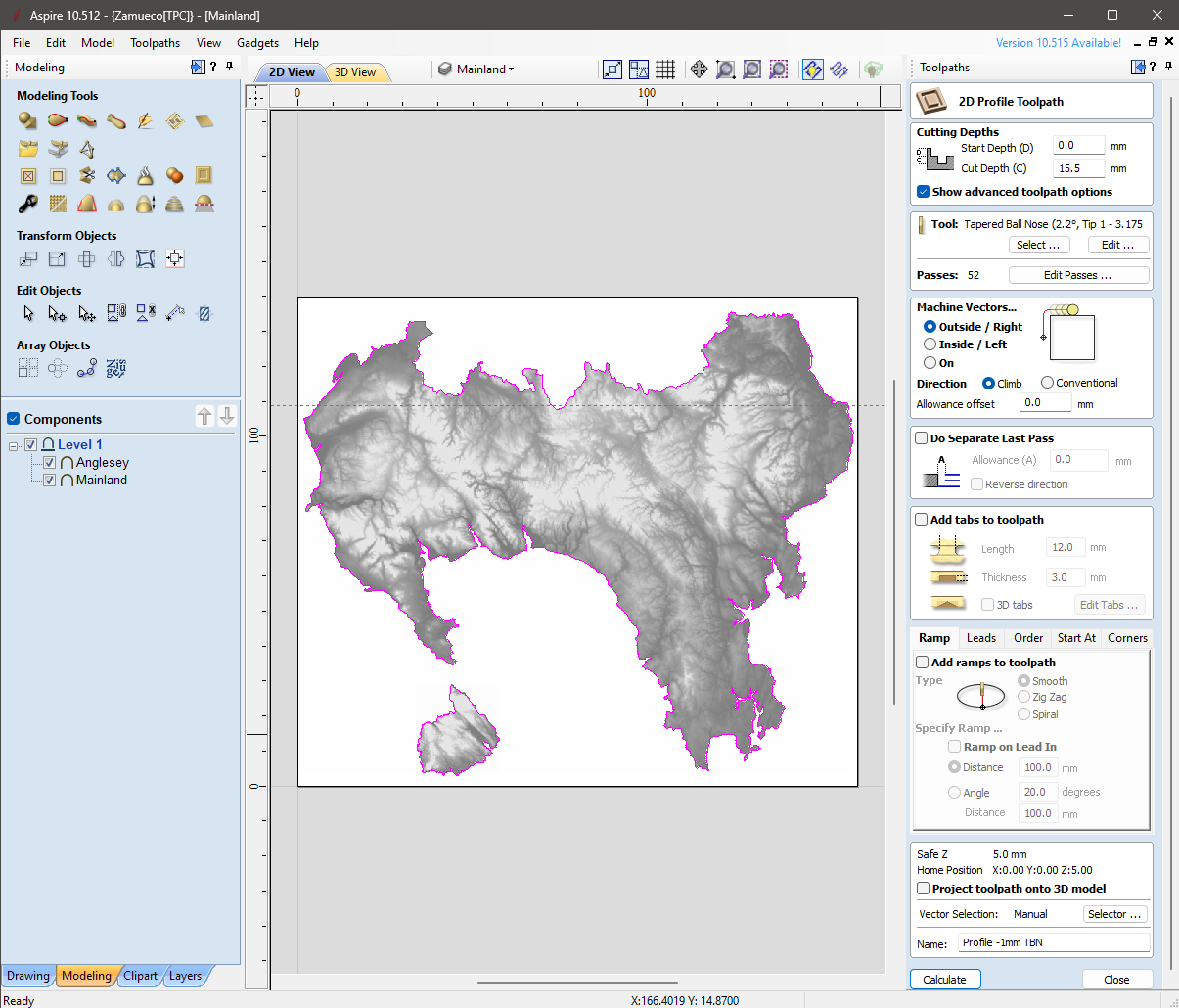
Finally, I duplicated the first profile toolpath and just changed the tool to the 1mm TBN endmill, this can get into slightly smaller places than the 3.175mm BN endmill, and also leaves a better finish.
Simulating
Before I exported any of my toolpaths I simulated everything to make sure everything looked good and that nothing should go awry.
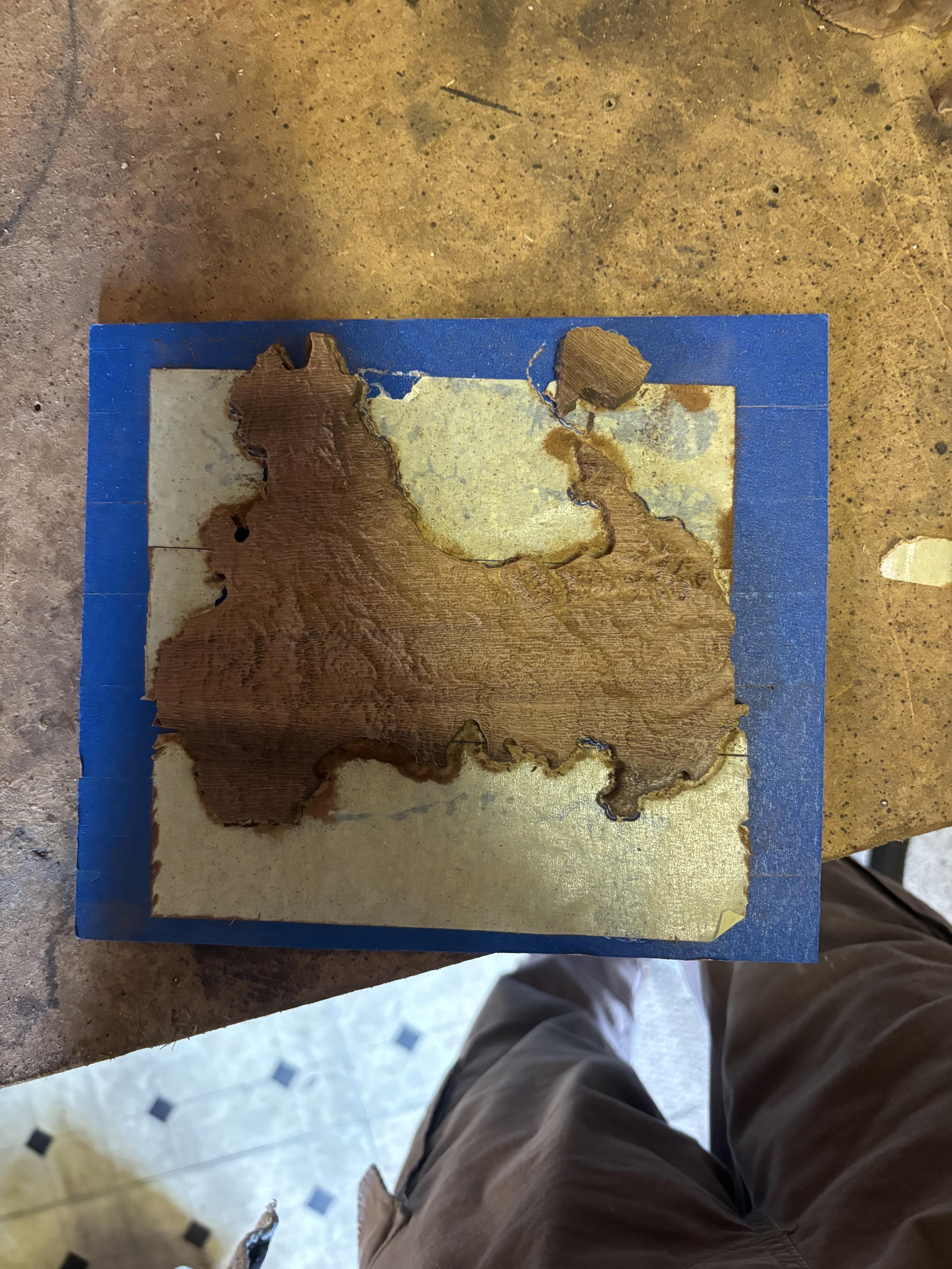
Material Prep

My material was some kind of rough-sawn dark hardwood. I wouldn't recommend using a softwood for this, as it would probably chip and leave quite a splintery finish. If your stock is already at dimension, then you can skip most of this step.
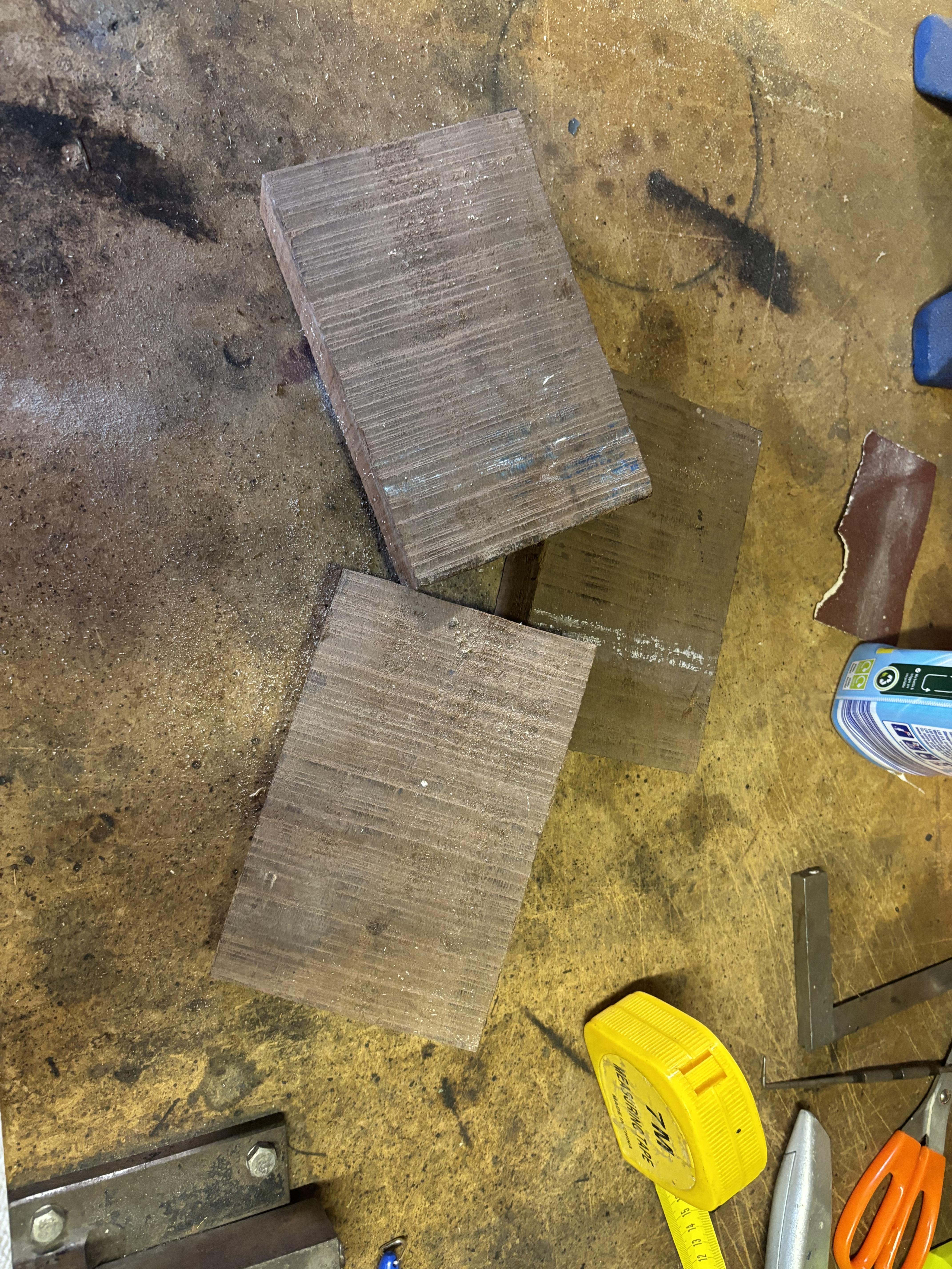
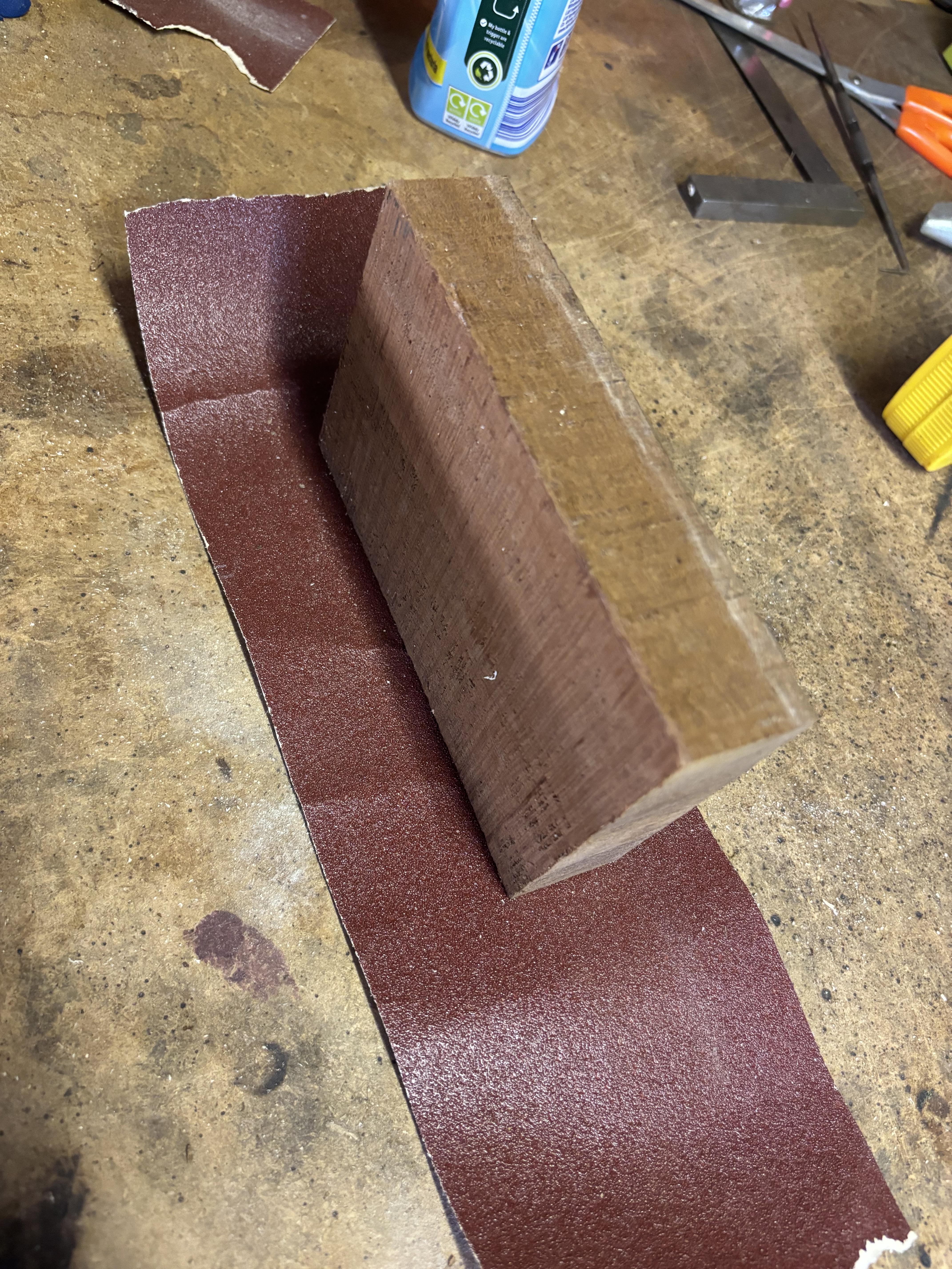
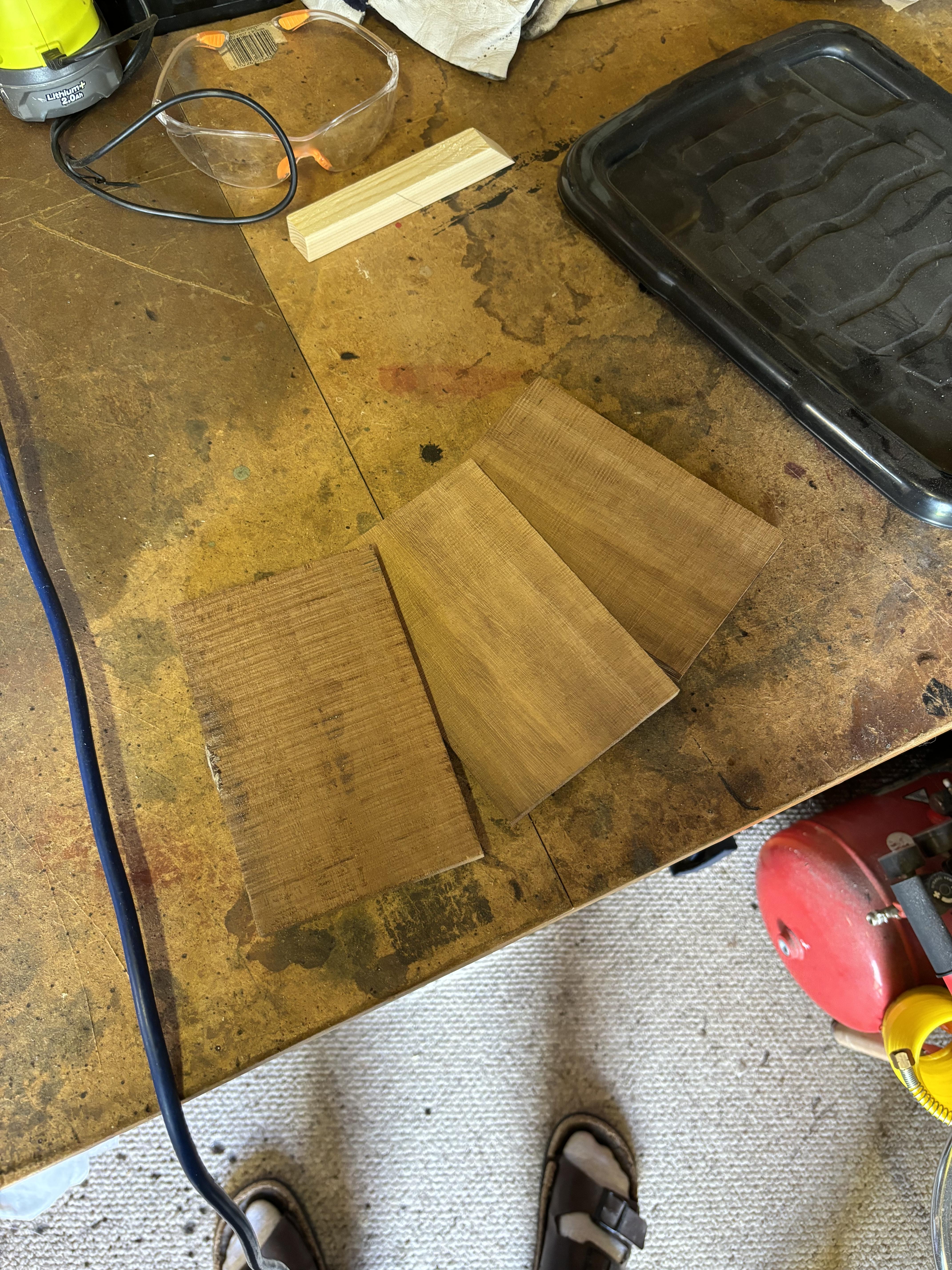
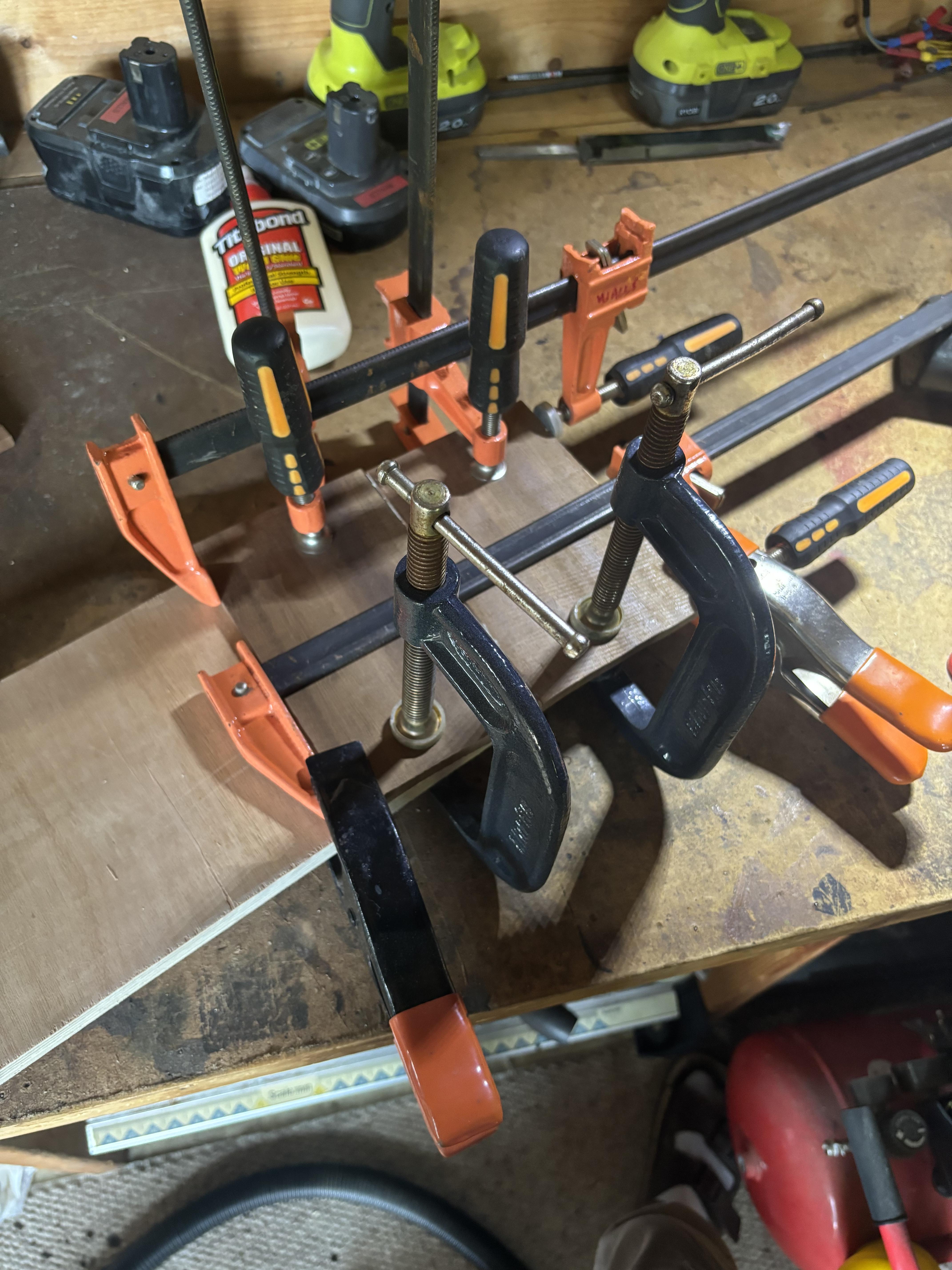
To start off with I used the CNC to face one side of my rough-sawn stock, sanding or a jointer would work as well. I then used some 80 grit sandpaper to smooth out one of the edges, making sure that it was 90° to the surfaced face. I then used a bandsaw to cut my stock into three pieces, around 12mm thick, running the surfaced face along a fence. Next, I glued two pieces together to make a wider board, pressing the pieces against a piece of plywood to ensure they were flat.
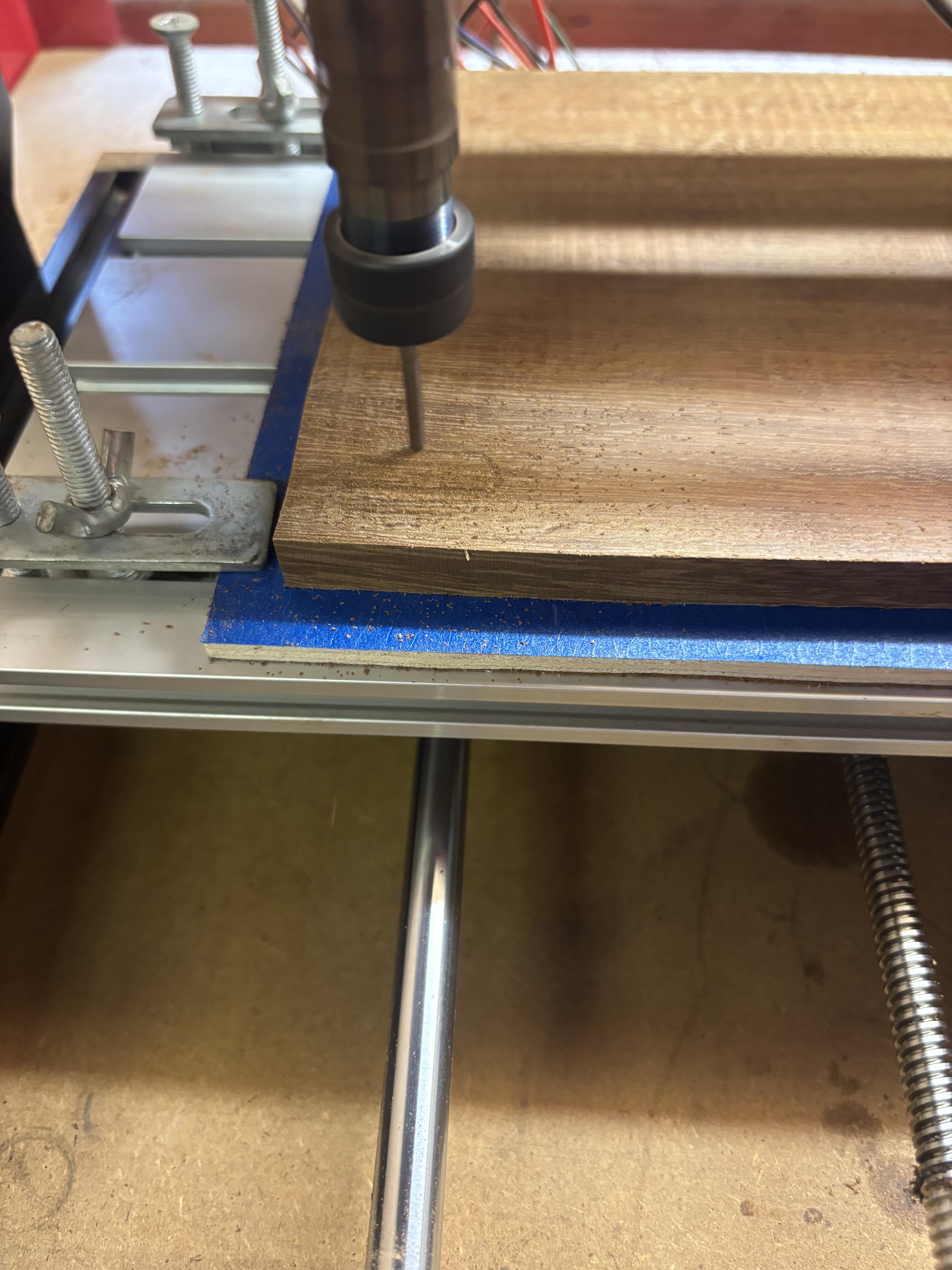
I then cut the board down to width on the bandsaw and used the offcut and the last slice to make another blank. Using masking tape, I covered the back side of the blank and then covered one side of a scrap piece of plywood, which is about 5cm longer than my blank, with masking tape too. I then generously covered the blank with superglue and pressed it firmly in the centre of the plywood.
The 2.5cm overhang of the plywood can then be used for the clamps to hold the material down.
Cutting
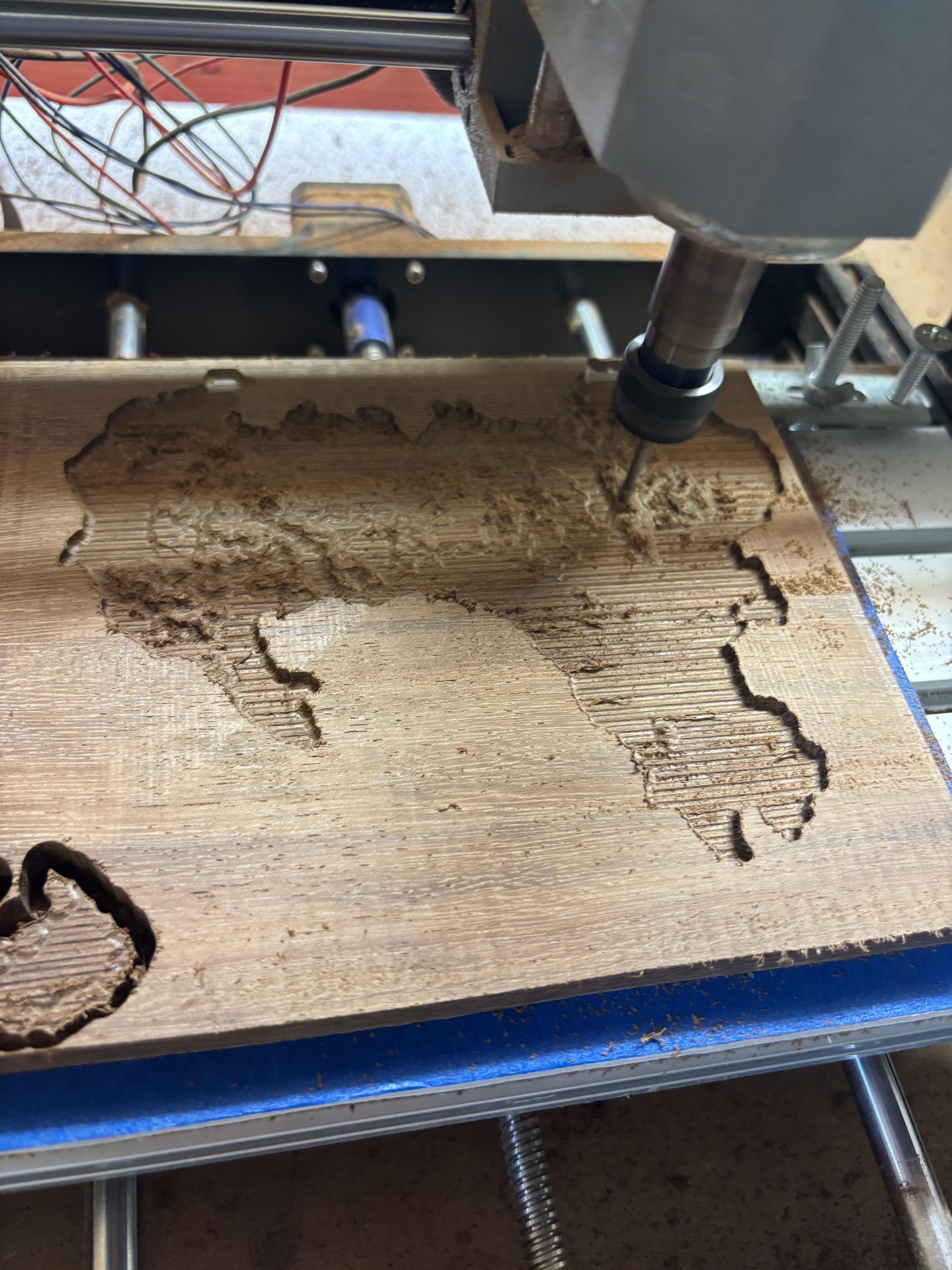
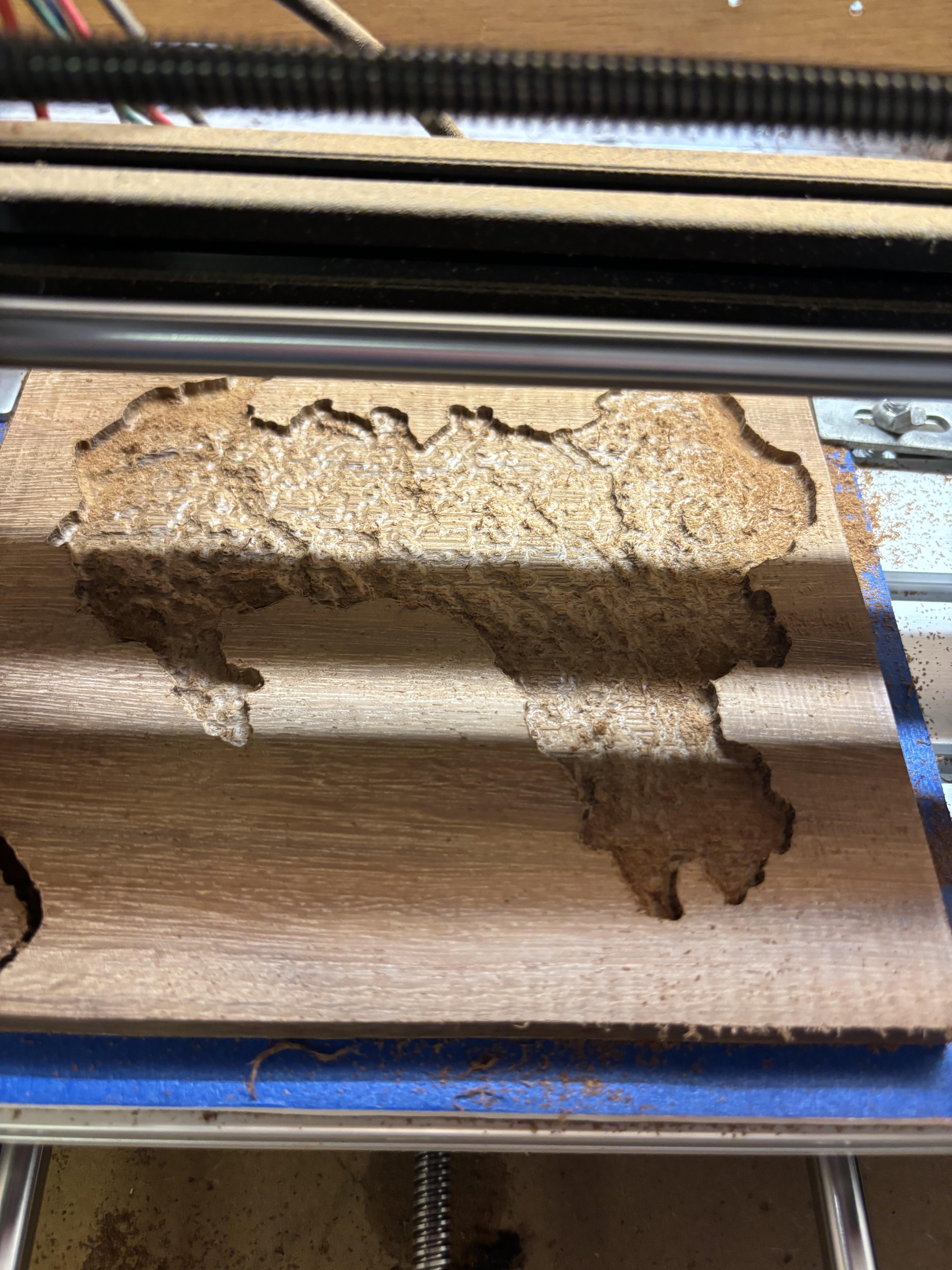
Given all the prep work we've put in so far, the actual process of cutting the material out is fairly easy, if only quite time-consuming.
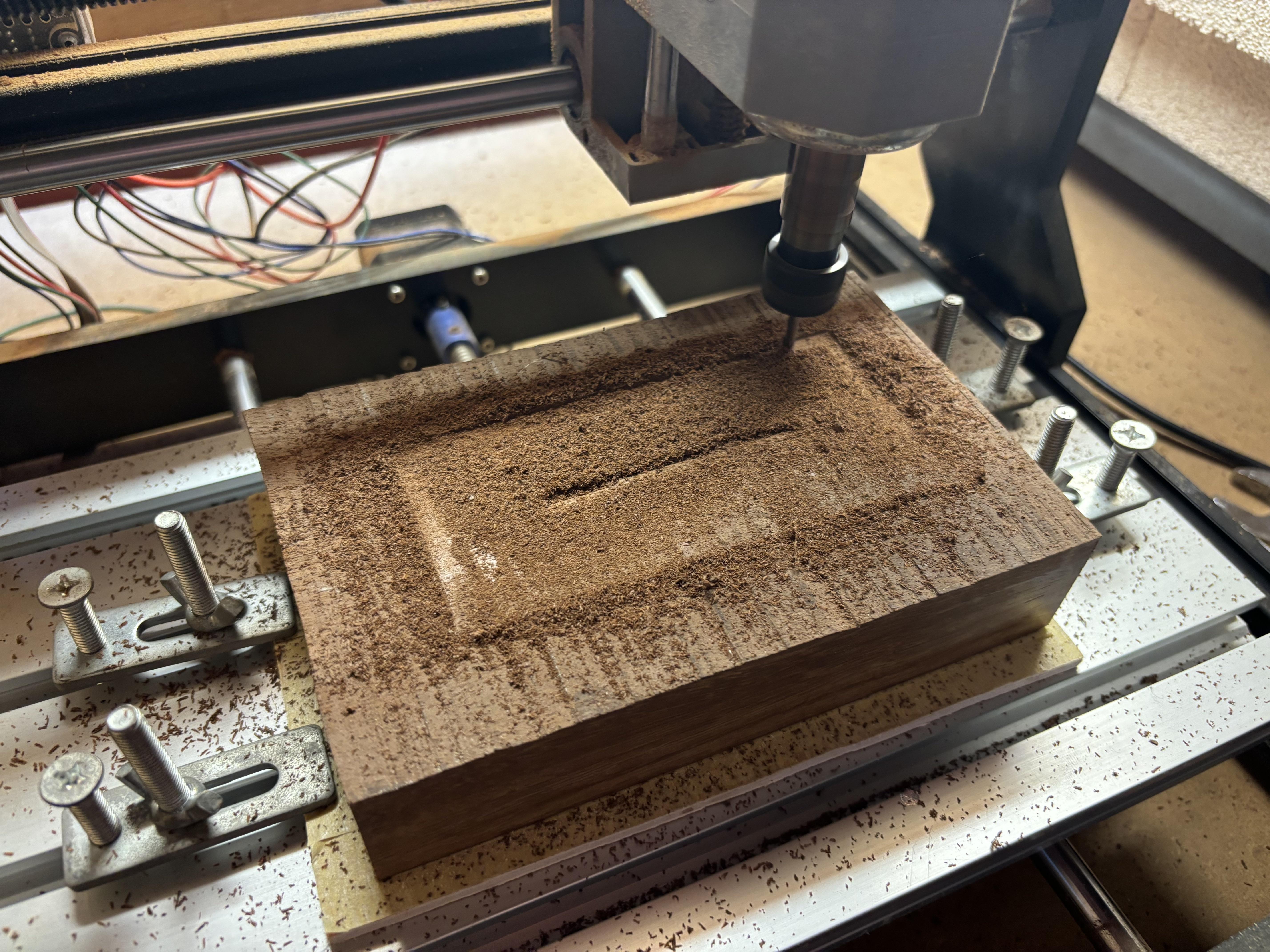
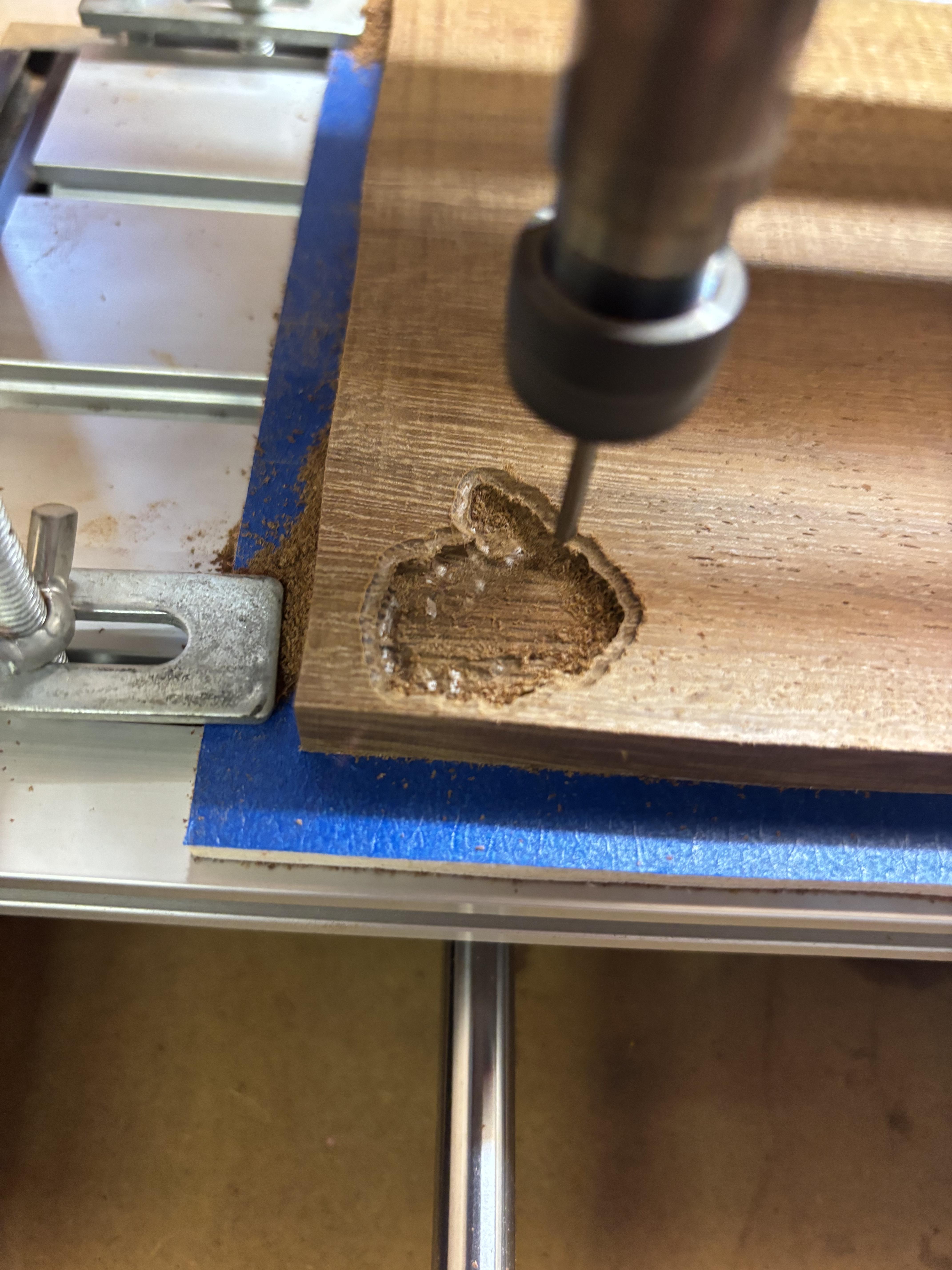
To start with I faced the material, if your material is fairly flat then this can be skipped, but mine was quite rough and the height was fairly uneven. I first set the Z height so the end mill was barely touching the highest point, and then moved it over to the bottom left corner. Then I started the program and watched it go. Due to the roughness of my stock, I did have to do this a few times, until I got it flat. When you're happy, it is worth checking the thickness of the stock, and updating the model thickness in Aspire if needed.
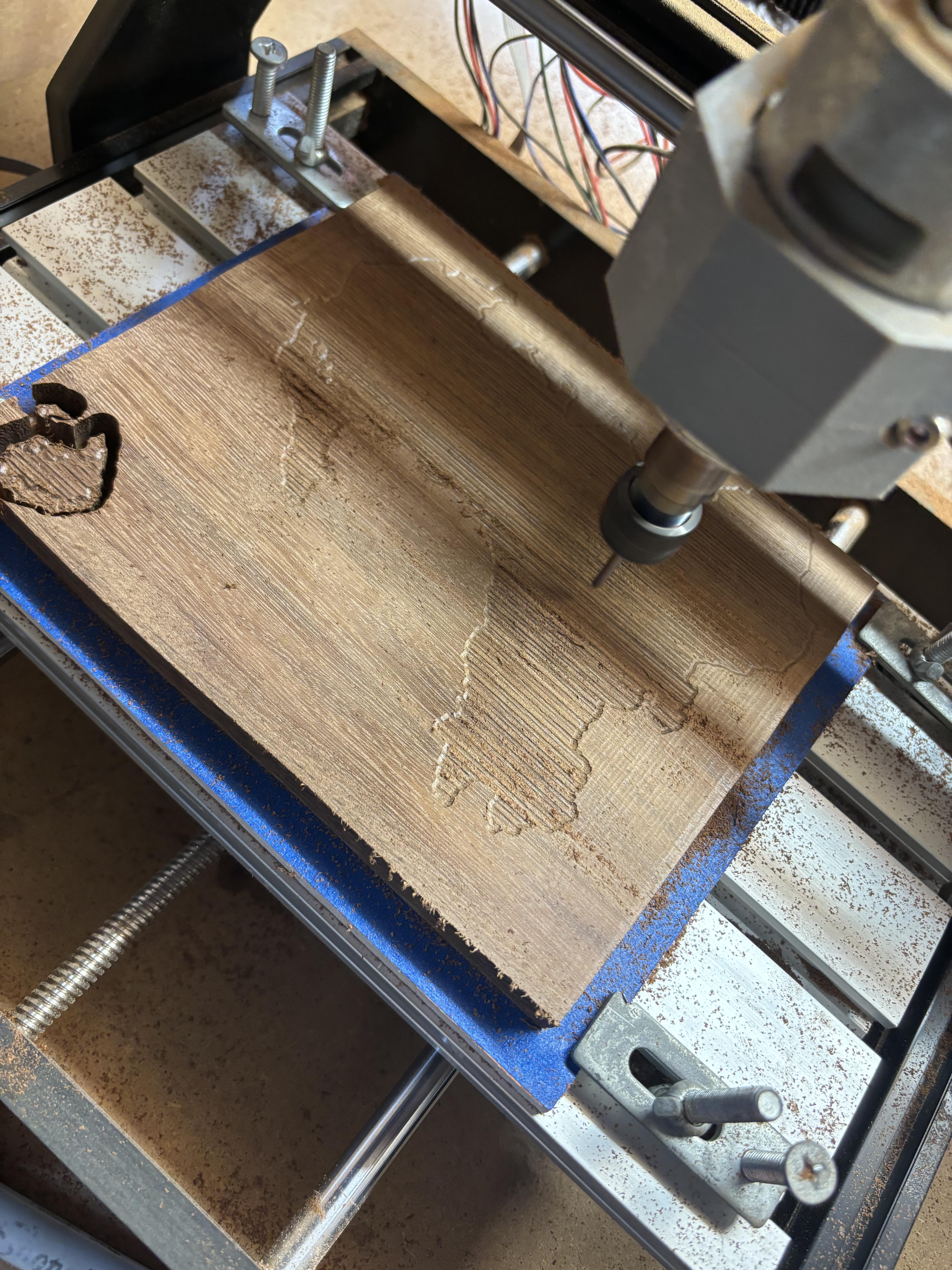
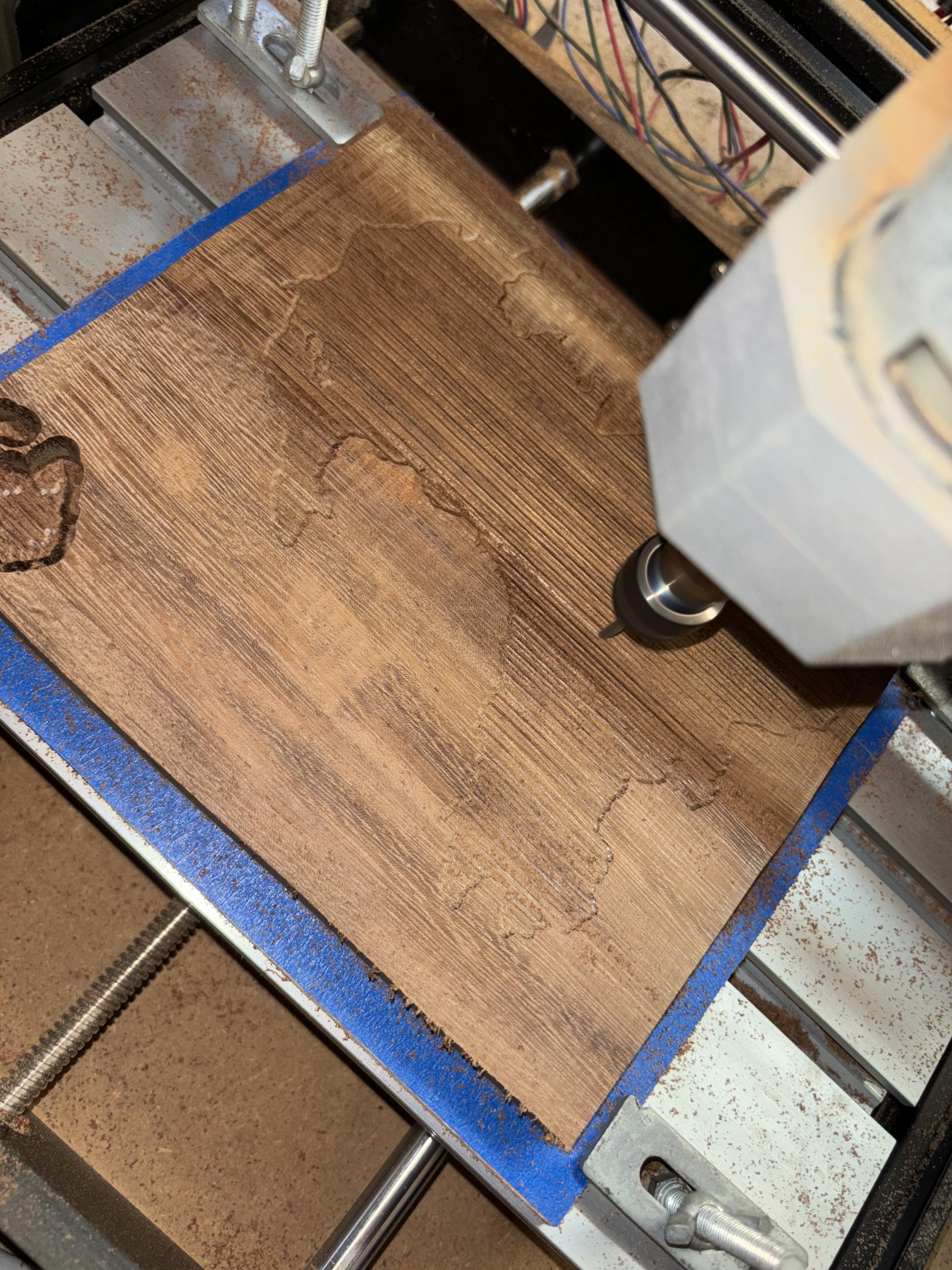
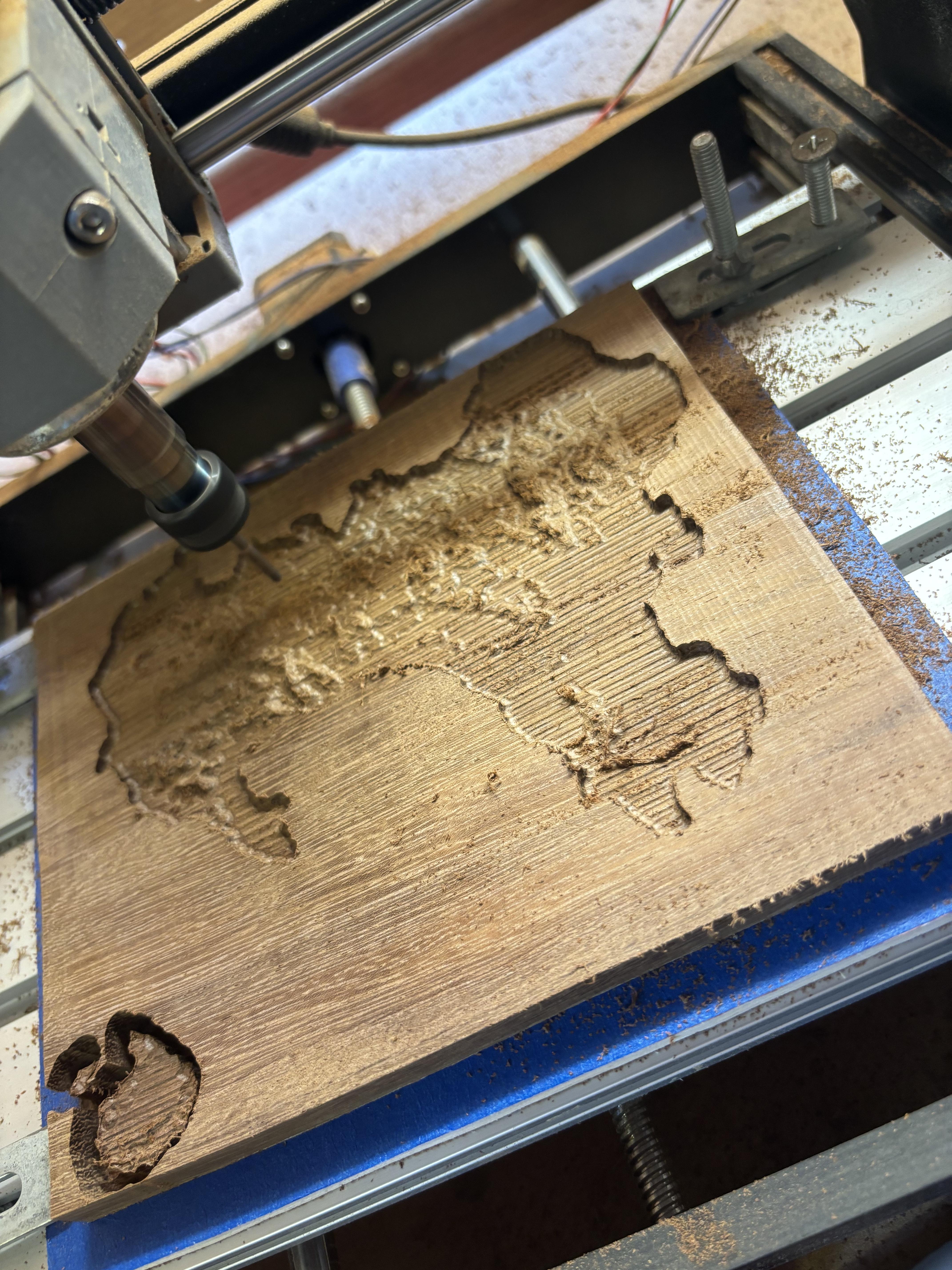
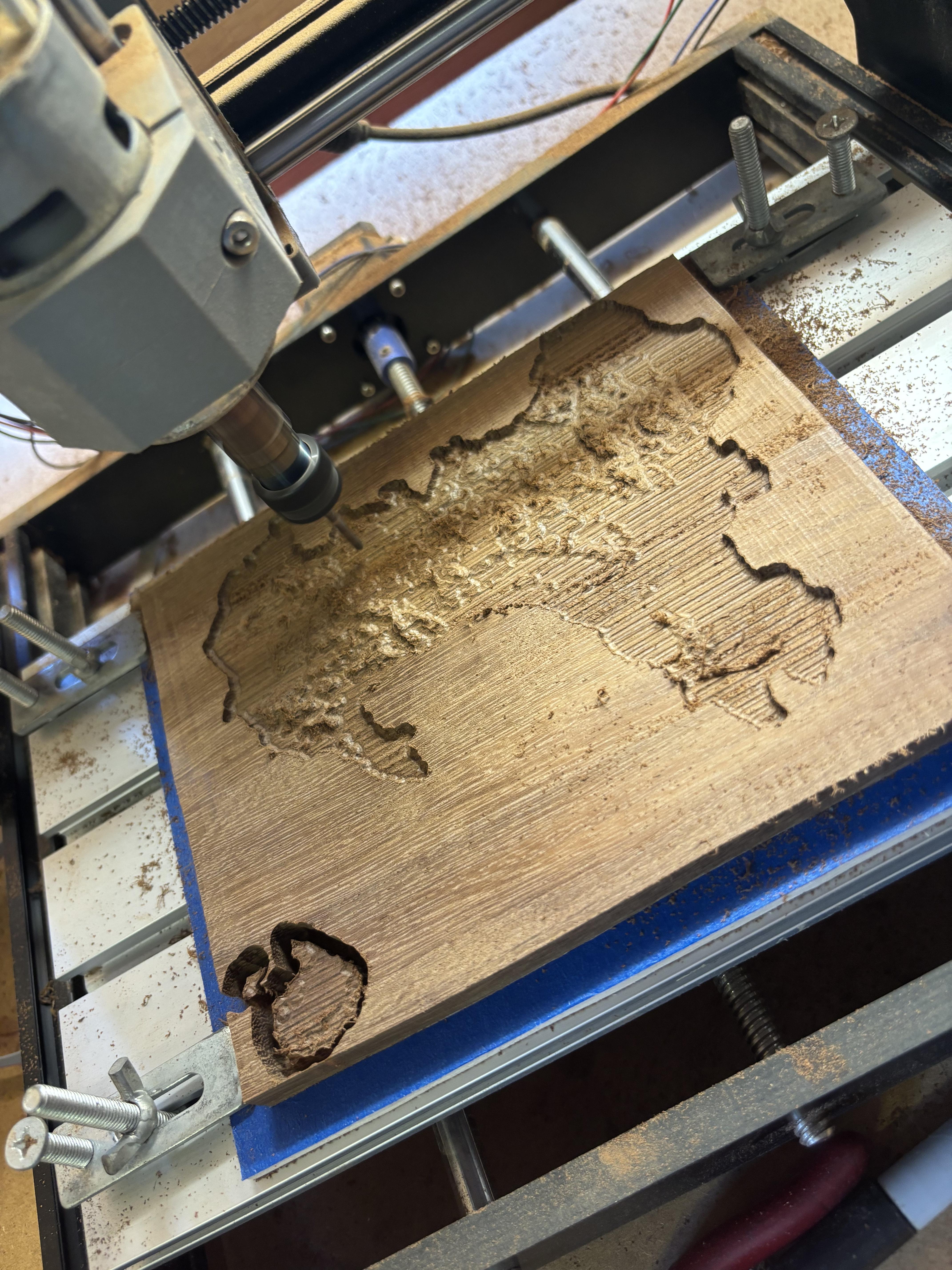
Changing to the Ball Nose End Mill, I reset the Z height, so the the ball nose was just barely touching the surface, brought it back to the same XY position in the bottom left-hand corner and ran the 3D roughing toolpath, and then the first profile path.
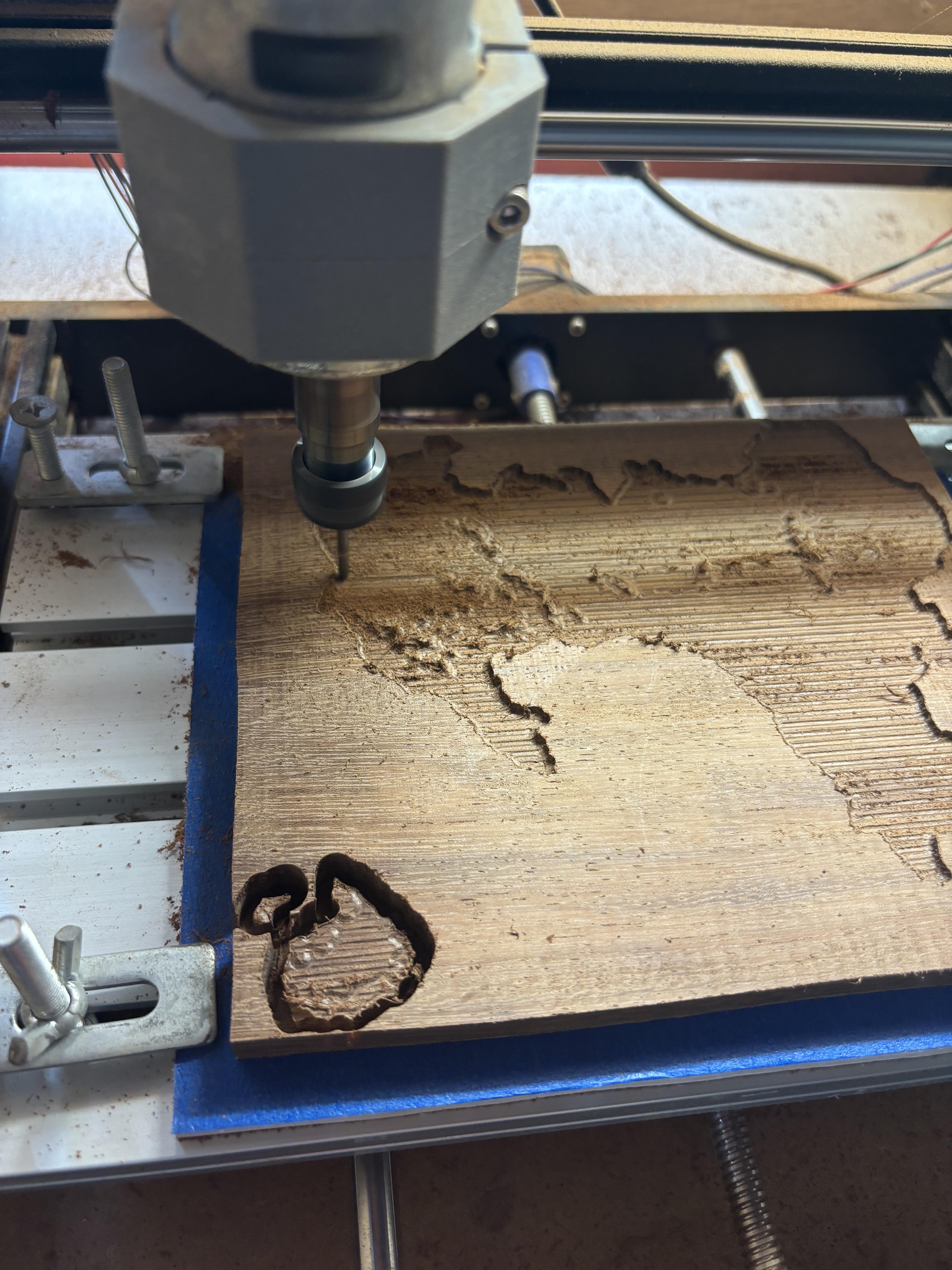
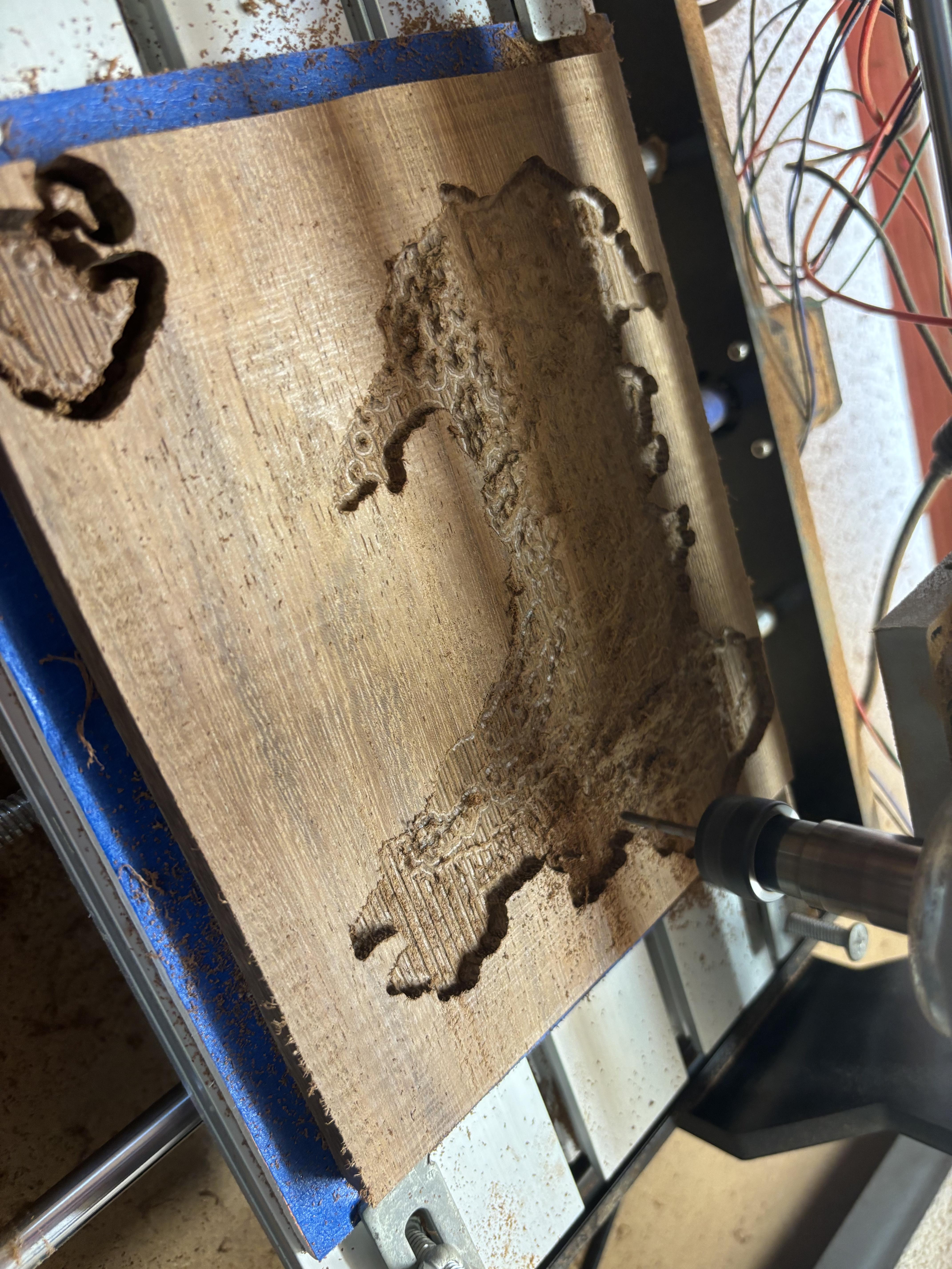
Finally, I changed to the tapered ball nose bit, reset the Z height, being extra careful to bring it back to the same XY point, and ran the 3D finishing path, and the final profile path and that is the machining done!
Finishing
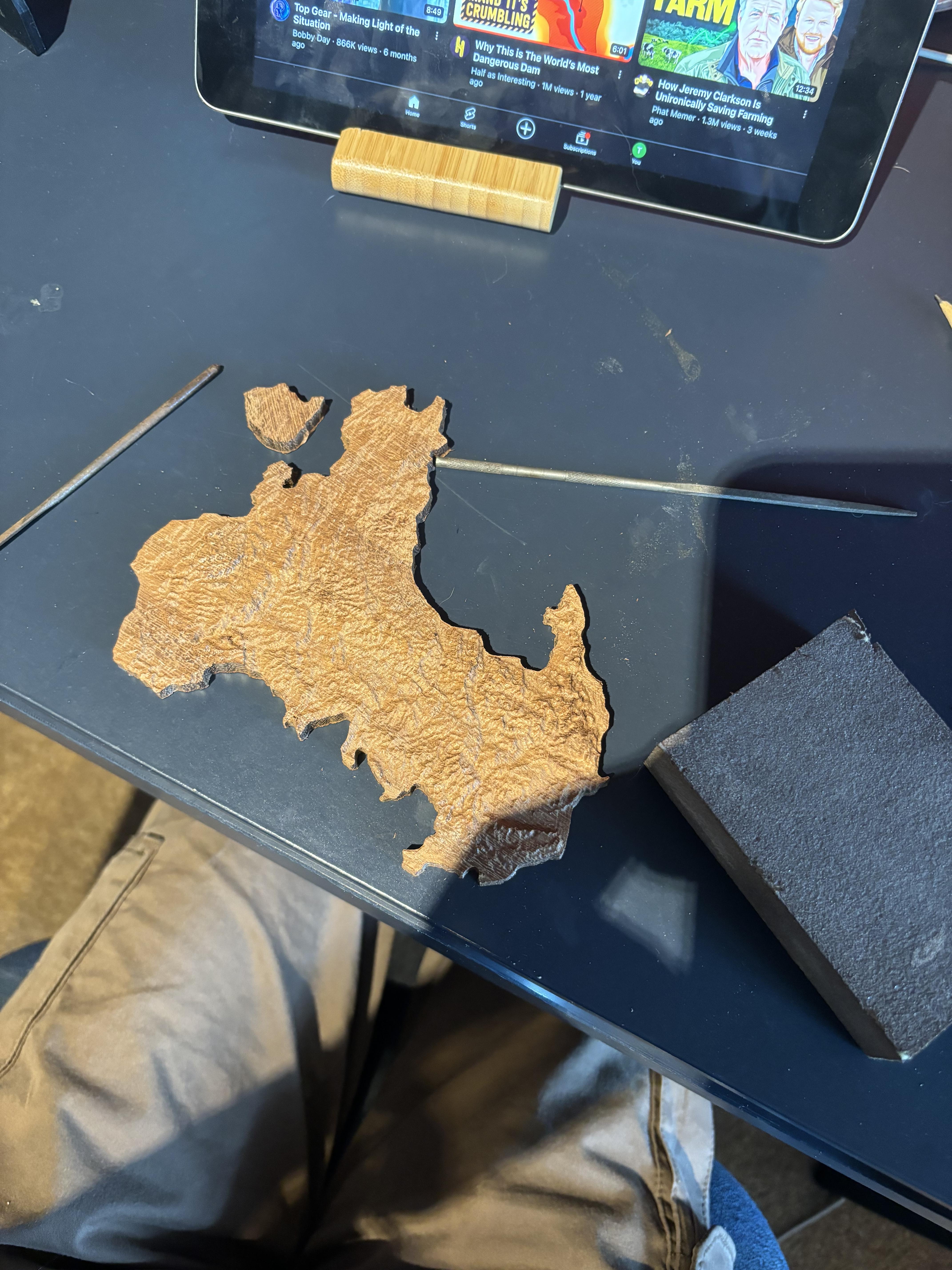
Taking the piece off the machine and removing the masking tape, you might find some splintering and burrs around the edges; I used some needle files and a sanding sponge to remove these.
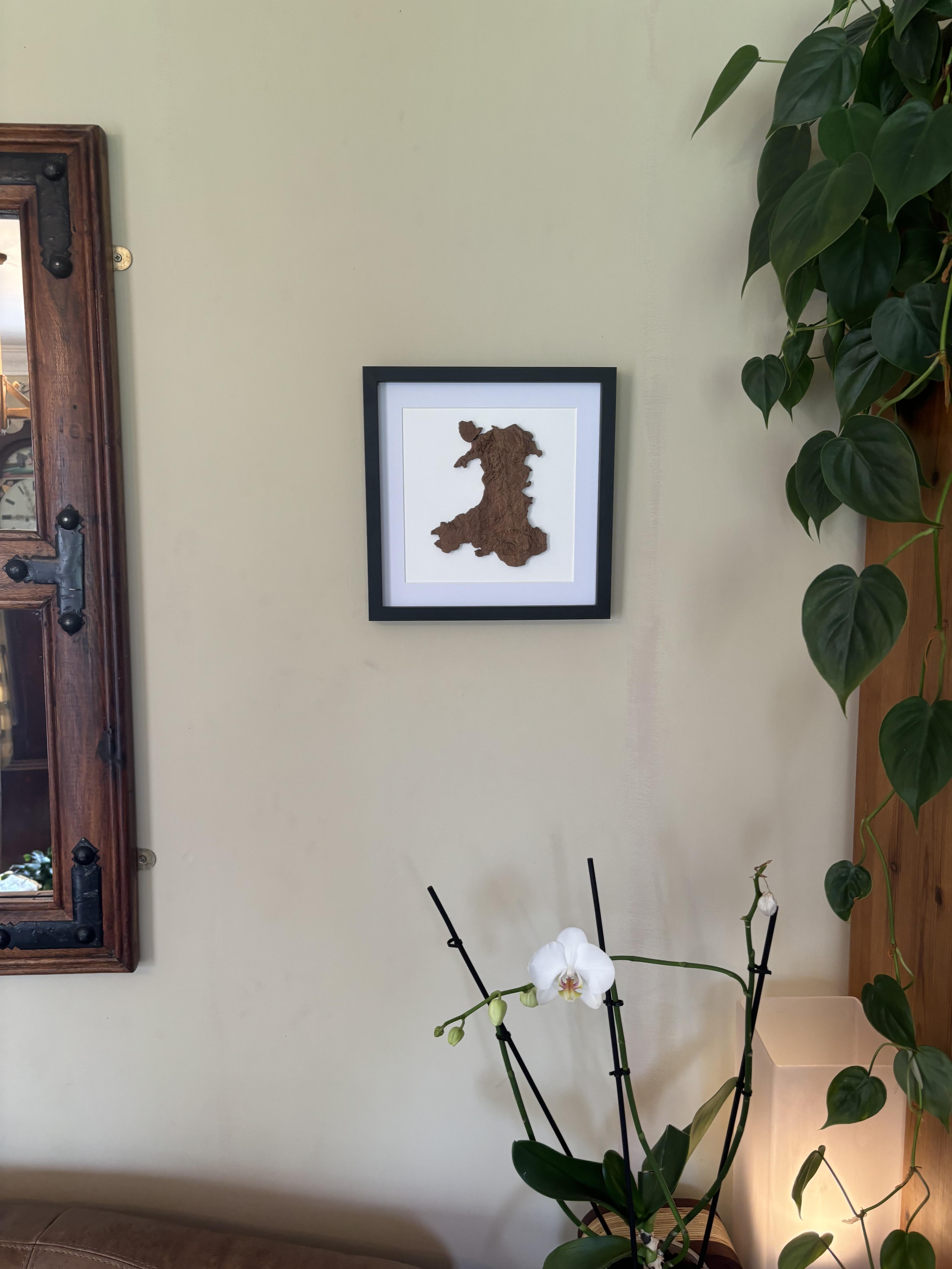
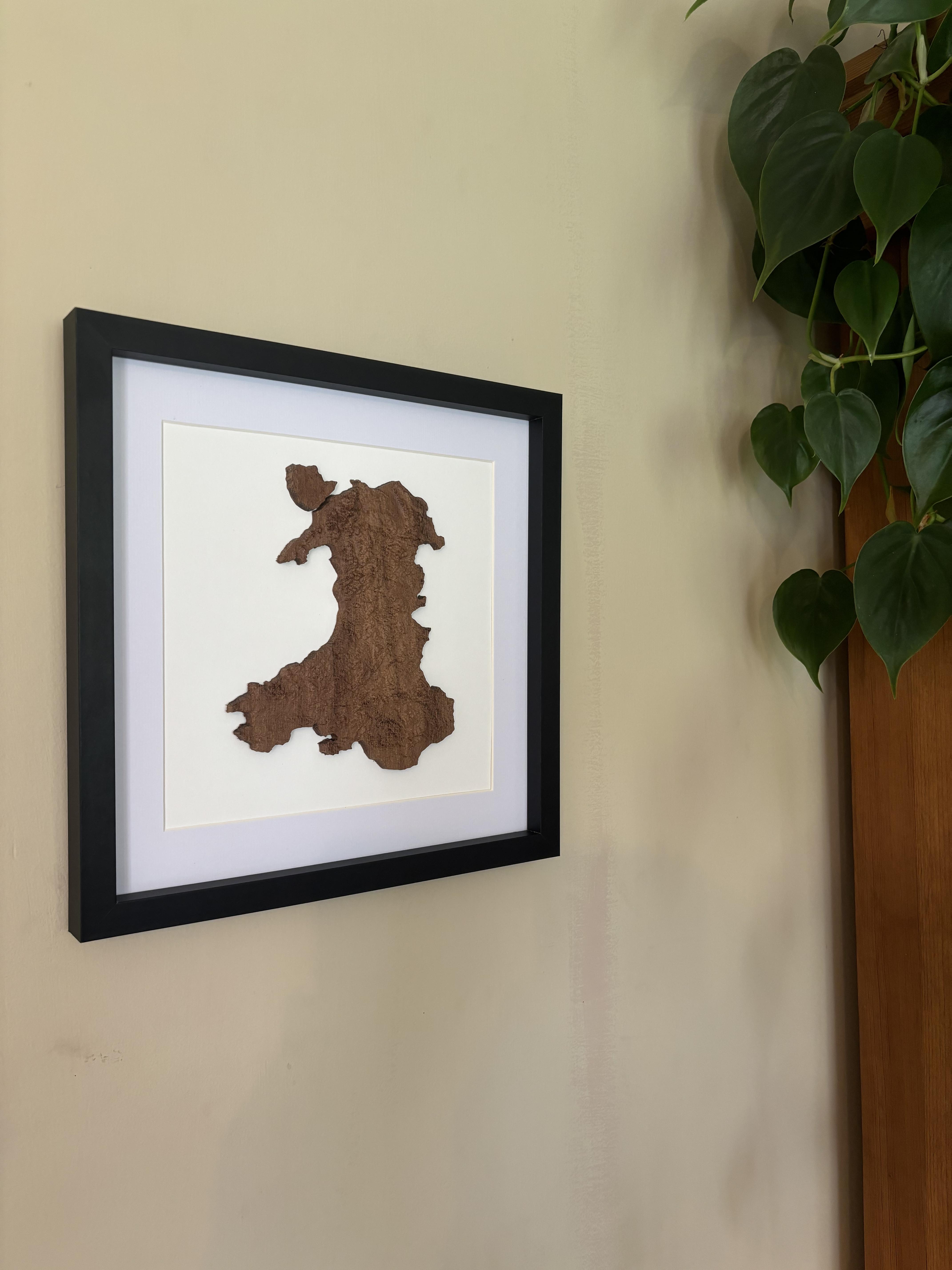
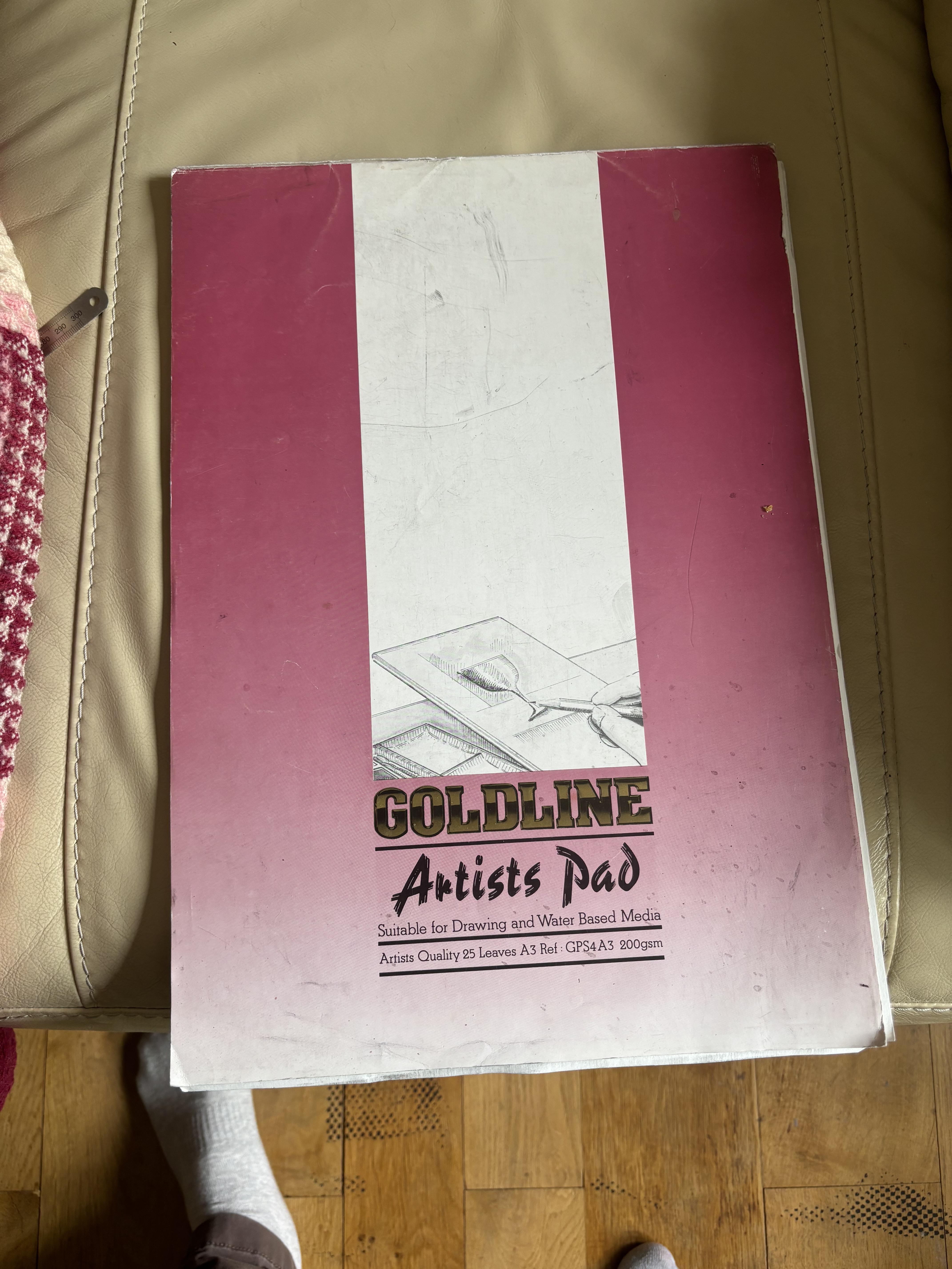
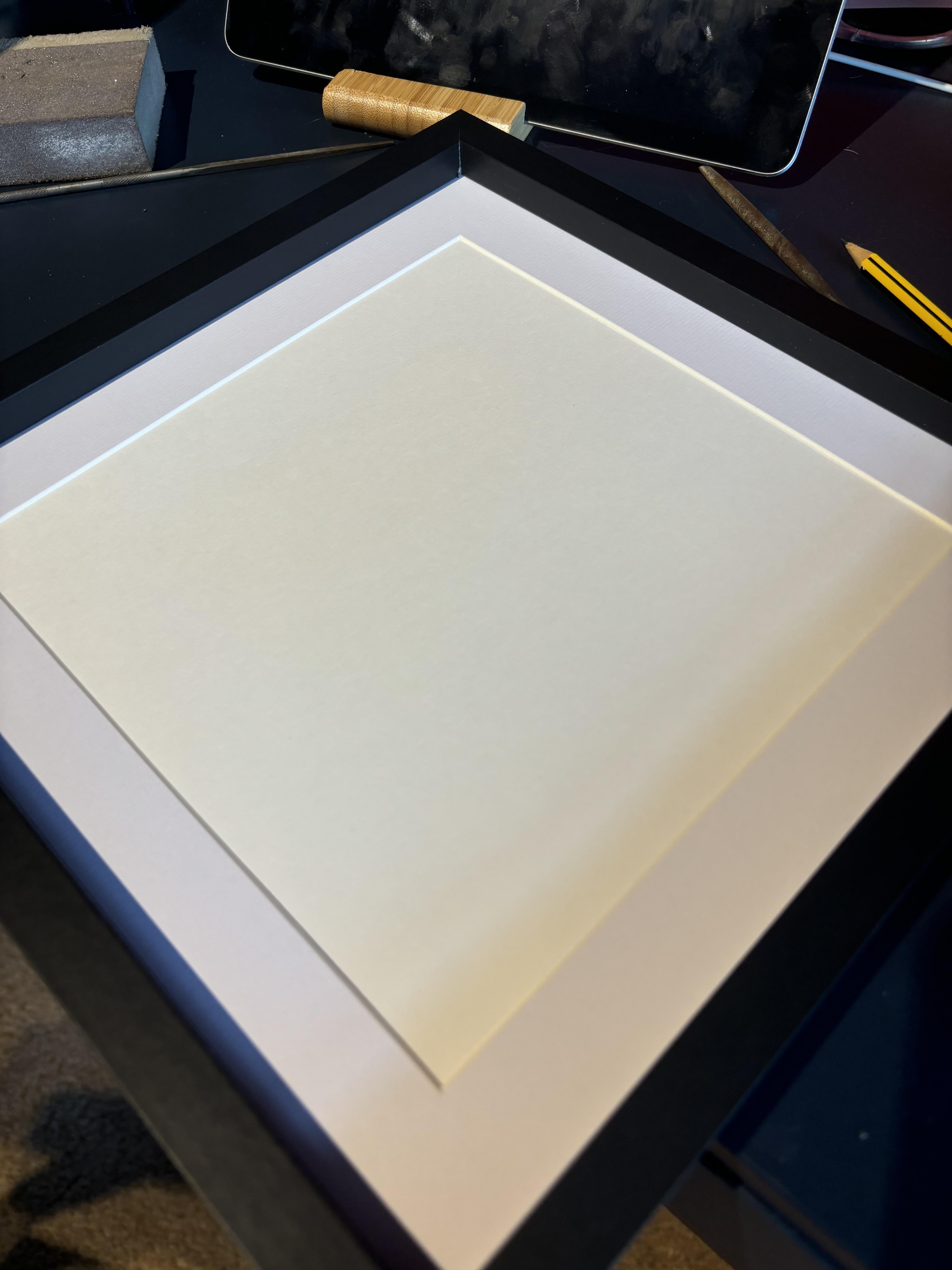
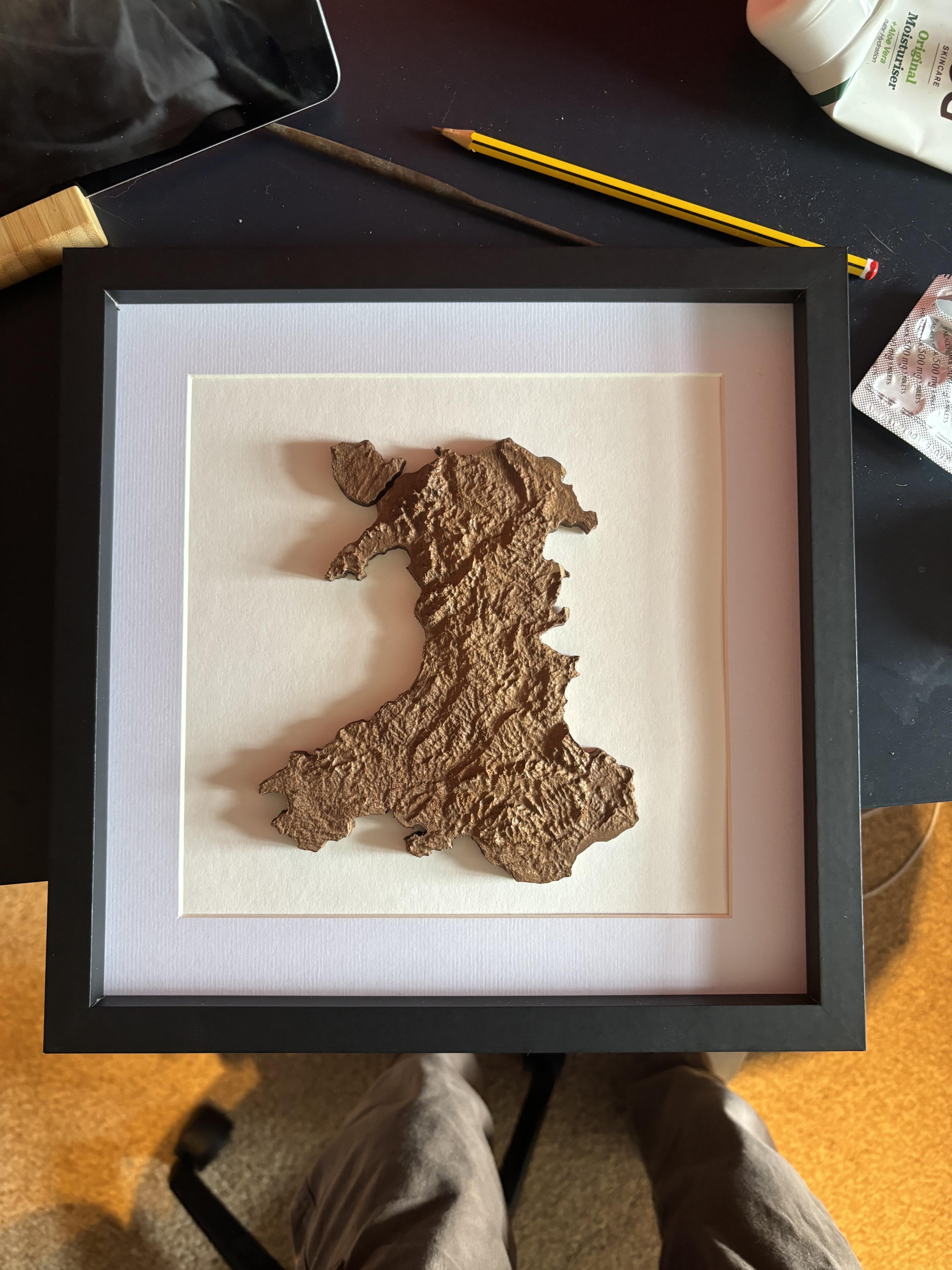
For the frames I used are from Amazon. I knew that with the glass they wouldn't be deep enough, so I removed it so the map would be open, and I think it works for the best as it highlights the topography better. I then cut some drawing paper down to size and positioned it into the frame. I did have to cut down some mount board to take into account the thickness of the glass. I then used some super glue to glue the mainland down to the paper, and then Anglesey island afterwards.
Overall I'm really happy with how this turned out, I think they are going to make great gifts and was a really fun entry into Aspire and a great opportunity to learn more about my little CNC.