WakeupNow – Smart Alarm Clock
As everyone knows, life of students are very hard, they have a long day with lectures, a lot of homework and in general, they have a crazy life. They have time for nothing, and if you suggest them to add some hours to the day they will be glad. Unfortunately, we can't do that, but now the students can use our WakeupNow alarm clock that will ensure you will wake up on time and fast.
WakeupNow is a smart alarm clock, created to ensure tired people will wake up fast and on time.
Who we are?
Three Computer Science students from the Interdisciplinary Center (IDC), Herzliya, Israel that are very tired from combining stressful and busy schedules – school, job, family, and so on.
All of us have some difficulties to wake up early in the morning and because of that, we know all the tricks to make people wake up even when you try to manipulate the alarm.
WakeupNow is our final project in the course “The Internet of Things (IOT)” course thought by Zvika Markfeld. Thank you for teaching us this amazing course.
We hope this alarm will make your wake up easier, and you will like.
Supplies
• 1 x ESP8266 Board (we used Wemos D1 mini)
• 1 x Micro-USB Cables
• 1 x Breadboard
• 1 x Sonar
• 1 x Led
• 1 x Piezo
• 1 x RGB Led
• 20 x Jumper Cables
• 1 x Temperature & Humidity Sensor (We used DHT22)
• 3 x 10K Ohm Resistor
• 1 x NeoPixel Matrix 8x8
• 1 x Speaker
Connections
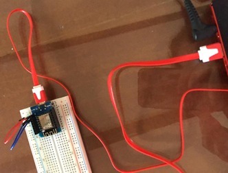
- Put the ESP8266 board on the up middle of Breadboard.
- Connect the Micro-USB Cable from the ESP8266 board to the USB port on the computer.
- Connect between 5V pin on ESP8266 board to plus (+) on Breadboard (red jumper cable) and between G on ESP8266 board to minus (-) on Breadboard (blue jumper cable (like in the picture).
- Sonar connection
- Connect Gnd to minus (-) on Breadboard.
- Connect Echo to pin D3 on the ESP8266 board.
- Connect Trig to pin D2 on the ESP8266 board.
- Connect Vcc to plus (+) on Breadboard.
- Led connection
- Connect long leg with 10K Ohm resistor to pin D4 on the ESP8266 board.
- Connect short leg to minus (-) on Breadboard.
- Piezo connection
- Connect black jumper cable to minus (-) on Breadboard.
- Connect red jumper cable to pin A0 on the ESP8266 board.
- Speaker connection
- Connect one of the jumper cables to minus (-) on Breadboard and the second with 10K Ohm resistor to pin D8 on the ESP8266 board.
- RGB Led connection
- Connect yellow jumper cable to pin D5 on the ESP8266 board.
- Connect red jumper cable with 10K Ohm resistor to plus (+) on Breadboard.
- Connect green jumper cable to pin D6 on the ESP8266 board.
- Connect blue jumper cable to pin D7 on the ESP8266 board.
- Temperature & Humidity sensor connection
- Connect 3.3V to pin 3.3V on the ESP8266 board.
- Connect #D4 to pin D4 on the ESP8266 board.
- Connect GND to minus (-) on Breadboard.
- NeoPixel Matrix connection
- Connect DOUT to pin D1 on the ESP8266 board.
- Connect 5V to plus (+) on Breadboard.
- Connect GND to minus (-) on Breadboard.
Comment
We did not have a space to insert all of the components so we connected only part of them for each stage of the alarm.
Software Preperations


Arduino IDE
Adafruit IO
- Create Account
- Add 3 new feeds
- FaceReaction
- Temperature
- WakeupTime
- Add new Dashboard named "Alarm Diagnostic"
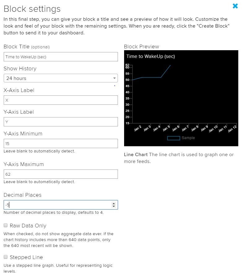
- Add a Line Chart with settings like in the pictures.
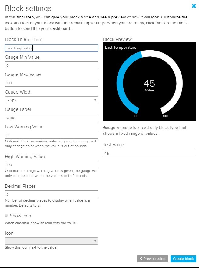
- Add a Gauge Block with settings like in the pictures.
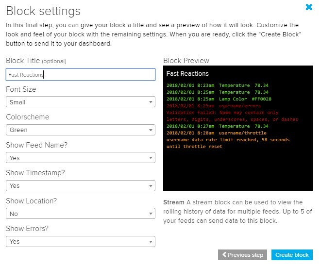
- Add a Stream Block with a setting like the pictures
- You can see how the dashboard looks like in the pictures.
Blynk
- Download to your phone
- Scan the QR Code in the pictures to get the project.
Code
Download the file "finalProject.ino" for the code of this project.
Open the code in Arduino IDE, and choose the relevant board – "LOLIN (WENOS) D1 R2 & mini".
When you run the serial monitor make sure you are on 9600baud – the will help you track if you have any errors.
In order to connect to Wi-Fi, Adfruit IO and BLYNK you need to modify all the relevant places in the code – make sure you do it.
Downloads
Choosing When to Wake Up
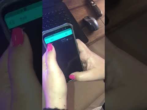
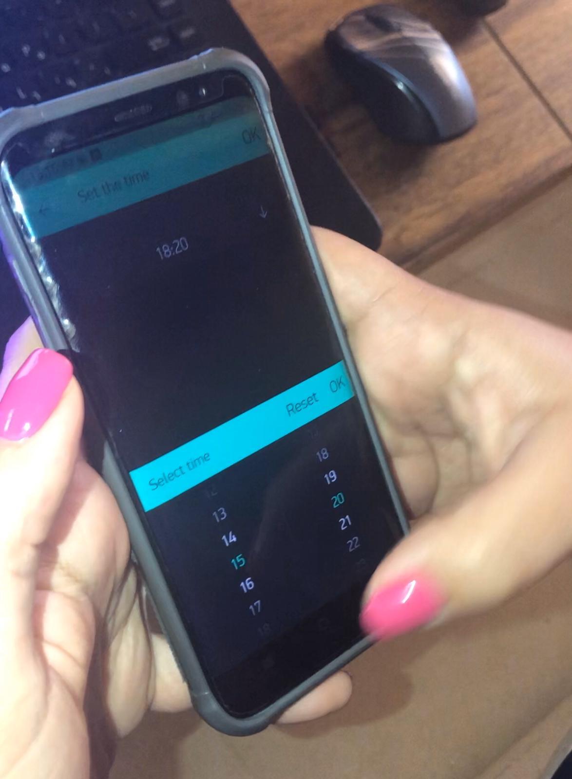
Take your cellphone and choose the time to wake up in the Blynk app.
The Led will turn on to notify you that you have set an alarm and the time chosen to wake up will be shown on the led matrix in the red color.
Alarm Is Ringing
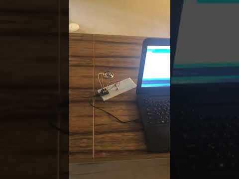
When it is the time to wake up, the alarm will play a modern version of "A Whole New World" and the RGB
led will blink in different colors.
This will continue until the user successfully deactivated the alarm (in the next videos you will not hear the alarm and will not see the led because of space problems).
Stopping the Alarm - First Steps
In order to stop the alarm you need first to follow those steps:
- Get close to the alarm, specifically the Sonar, it will pick you up and will unlock the next step.
- In the next step, the Piazo will be activated and you will need to knock 3 times (there is no time restriction between knocks) to unlock the last step
Stopping the Alarm - Final Step
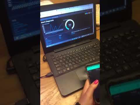
In the last step, the display in the NeoPixel Matrix will change to an equation and you will need to send the answer using Blynk, answer correctly and the alarm will stop.
After Deactivateing the Alarm
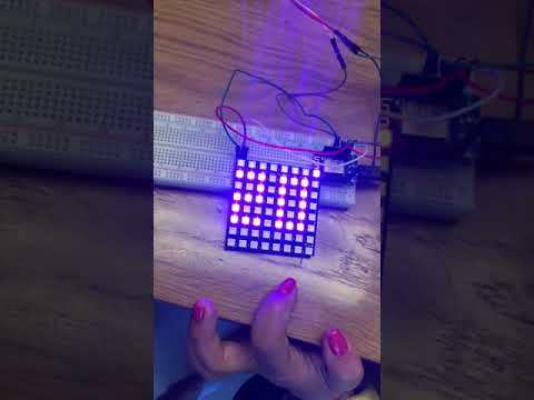
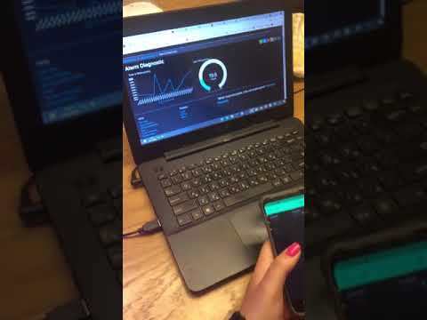
After you deactivate the alarm, you will see the room temperature (we wanted it to be the temperature of the current location using a service but every way we tried it did not work) in the NeoPixel Matrix, the temperature is being sent to Afafruit IO and you can check in the dashboard to see the last recorded temperature.
This alarm clock saves the time from when the alarm was activated until deactivated and send this to Adafuit IO. If the wake-up time is less than 3 minutes the user will get notified in the Fast Reaction Block, else if it took more than 5 minutes to wake up the user will get an email to remind him he needs to work on himself.