Voting Machine
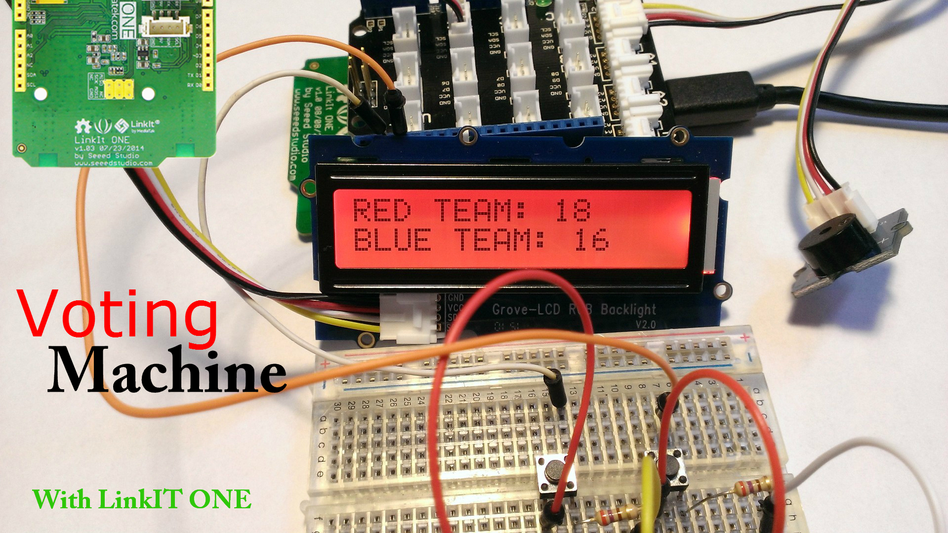
For all you teachers out there, taking a class vote can be hard sometimes. Keeping a tally of all the different hands that go up can be difficult, on top of some people who put their hand up and down. To counter that problem, I've created a basic voting machine. This voting machine allows for two different teams (Red and Blue) to press a button and vote. When they vote,they will get an audible tone (through our buzzer) to confirm their vote has been cast. Then, you will see their vote show up on the LCD screen. The color of the screen indicates which team is currently in the lead.
Supplies
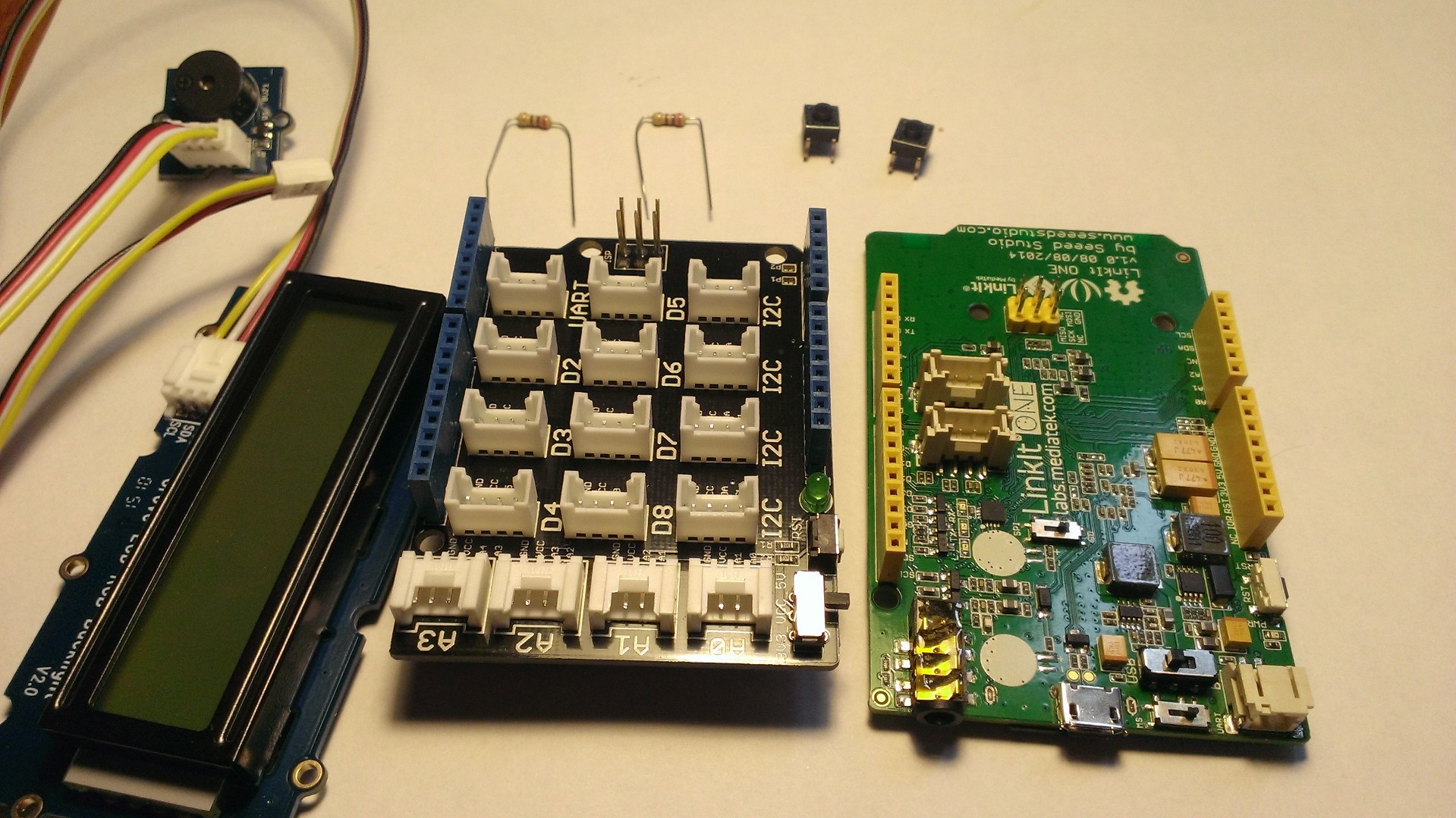
We'll use quite a few Grove components from SeeedStudio. The Grove - Starter Kit for Arduino will help us out immensely, so if you haven't picked one up yet, I would highly recommend you do so. Otherwise, we'll just need a few items from a standard electronics kit.
- LinkIT ONE
- Grove Base Shield
- Grove LCD RGB Backlight
- Grove Buzzer
- Push Buttons(2x)
- 10k ohm resistors (2x)
- Jumper Wires
- Breadboard (for prototyping)
Hook Up Your Grove Sensors
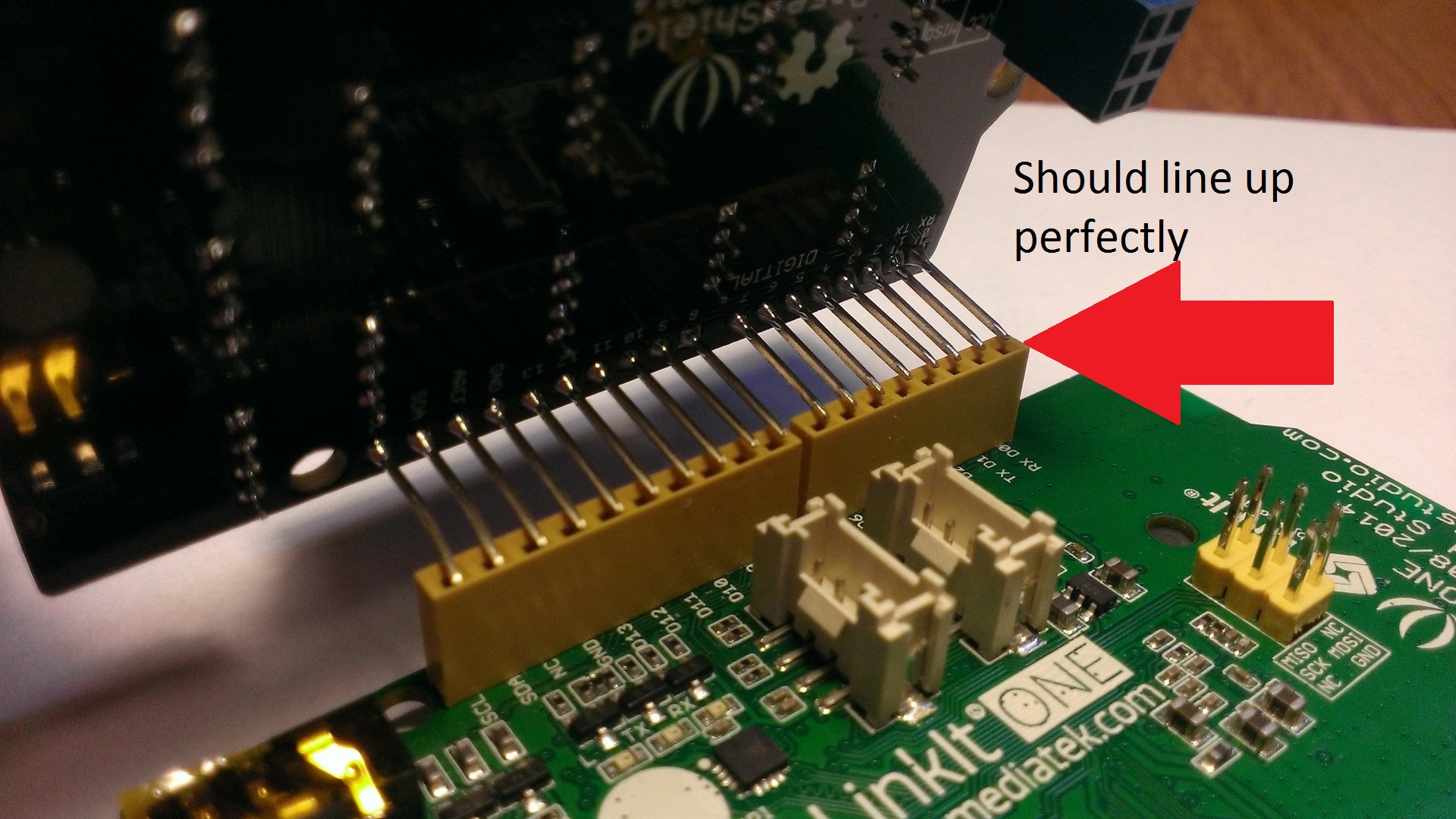
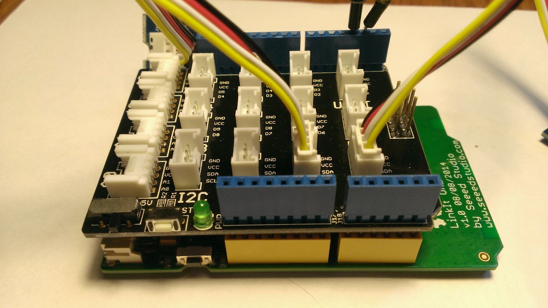
First, lets get all of our Grove Sensors attached (since that is the easiest).
The Grove Base Shield is relatively simple to attach. You simply line up the pins and push them in together. It can be a bit of a snug fit sometimes, so be careful to line it up correctly.
Then you'll want to connect the RGB LCD and Buzzer. The RGB LCD can connect to any I2C slot. Look at the picture above for a reference of where I plugged mine in.
Then, plug in the buzzer into one of the Analog slots (any slot that starts with A). I plugged mine into D6, so if you plug it into something different, make sure you modify the code later to reflect that.
Hooking Up Your Button Circuit
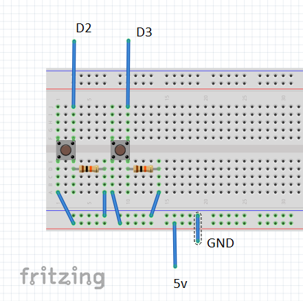
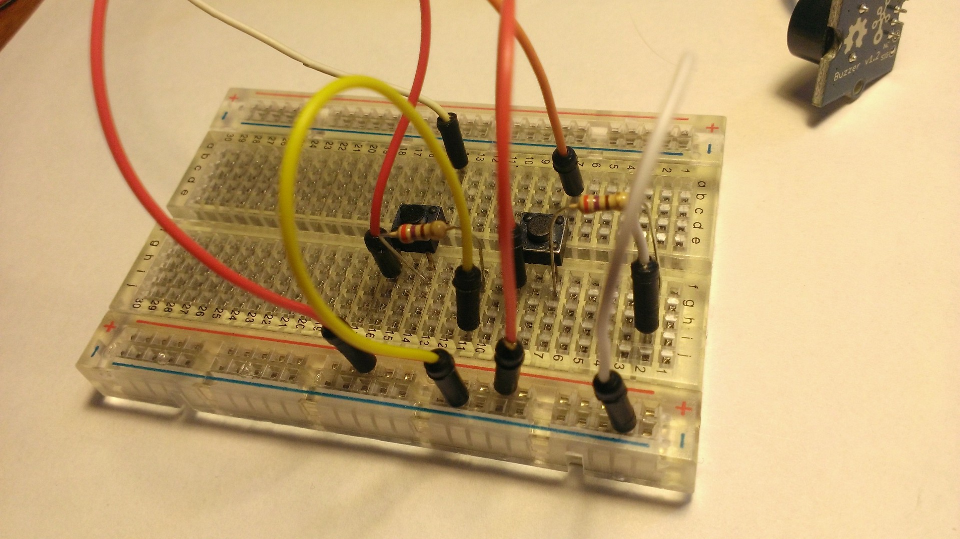
Next, let's put together our button circuit. This is a fairly simple circuit involving a button and pull-down resistor.
When our pushbutton is open (AKA, it isn't pressed) there will be no connection through the circuit so the pin will simply be connected to ground (this is through our pull down resistor). When we push it in, the button is closed, and it makes a connection across the legs. This connects the pin to our 5 volts and produces a HIGH signal. This is what we will look for in our logic: a high signal.
Deploying the Code and Logic
Finally, we will want to deploy our code to the LinkIT ONE to add some logic that ties everything together. Our logic path goes something like this:
- If a button is pressed, increment that team's votes that the button is tied too.
- Make the buzzer give a tiny buzz to confirm to the voter that their vote was cast.
- Then, we calculate which team has the lead. Turn the background of our LCD to that team's color
- If the team's votes are tied, let's turn on both colors!
Download this code file and deploy it to your device! Feel free to change any of the team's names to suit your needs!
Downloads
Deployment
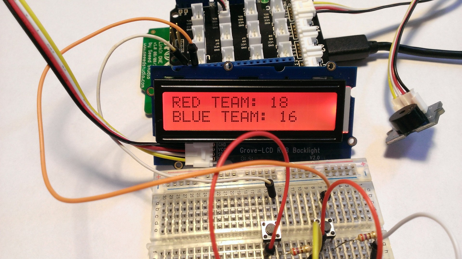
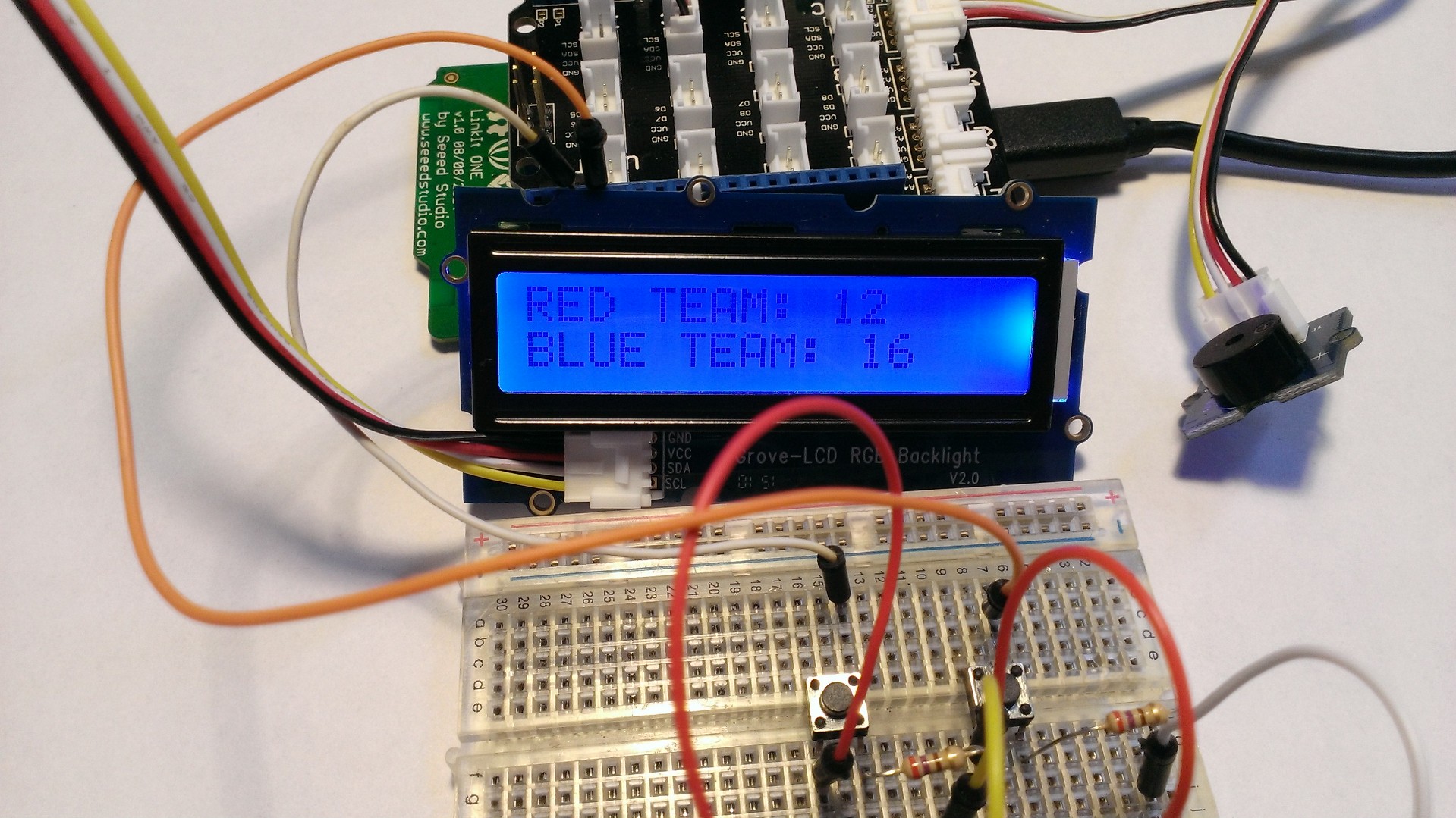
You did it! You now have a fully working voting machine! When a certain team is in the lead, you should see the LCD change color to reflect that.
Hopefully this has given you a solid project with the LinkIT ONE and made the voting process a little more automated! Good luck!