Voronoi Diagram Based PCB Lamp
by Arnov Sharma in Circuits > LEDs
4041 Views, 59 Favorites, 0 Comments
Voronoi Diagram Based PCB Lamp

.gif)
.gif)
.gif)

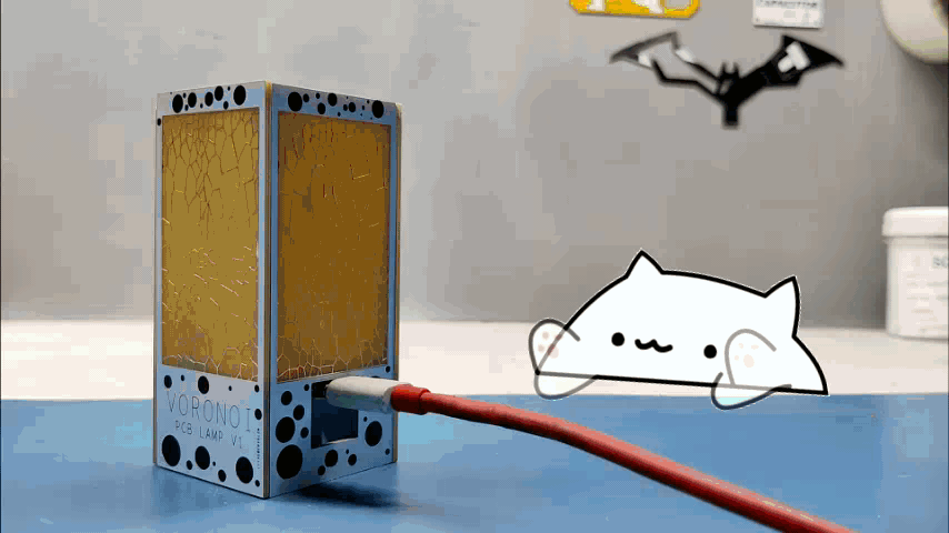
Hey, what's up you guys.
So this is my Voronoi PCB Lamp that contains Voronoi shape elements and is powered by an Attiny85 MCU, 64 WS2812B Mini LEDs are used in this project, and it's completely made out of FR4 PCBs.
It's kind of like an RGB Cube Project, the only difference is the shape and LED placement. (All LEDs are all placed inside)
This Instructables is gonna be about its built guide, so let's get started!
Supplies

Following were the things used in this project-
- Attiny85 SOIC8
- Custom PCBs- Main Square MCU PCB and Rectangular PCB
- WS2812B LEDs (i didnt use those, instead I use one of my previous matrix projects that contain similar but small RGB LEDs)
- USB Type C Port
- Diode M7
- 2R0 Resistor 1206 Package
- Arduino as ISP Setup for flashing the MCU
- SMD button
- UC202 Connector and wire harness
- Solder wire
Voronoi Diagram Explanation and Implementation

Voronoi Shape or Diagram is a simple mathematical complexity that often arises in nature, and can also be a very practical tool in science.
In mathematics, a Voronoi diagram is a partition of a plane into regions close to each of a given set of objects. In the simplest case, these objects are just finitely many points in the plane (called seeds).
the skin of a giraffe, corn on the cob, honeycombs, foam bubbles, the cells in a leaf, and a head of garlic, these are a few of Voronoi Patterns examples found in nature.
Check out its wiki article for more details-
https://en.wikipedia.org/wiki/Voronoi_diagram#:~:text=In%20mathematics%2C%20a%20Voronoi%20diagram,%2C%20sites%2C%20or%20generators).
Making a PCB Based on Voronoi Patterns


To get started, I first search around for an existing Voronoi pattern that I could use as making Voronoi completely from scratch would take time so I download a black and white image and converted it into BMP format to upload it into my PCB Cad software.
Rectangular PCB


.gif)
.gif)
First, I prepare the rectangular PCBs that will be the main structure of this whole project.
I prepared two PCBs for this project, one PCB which is for the walls of the rectangular lamp and another one that contains the main MCU (it will be the bottom part of the lamp), and one that contains the switch (it will be the lid).
This Lamp I'm making is gonna be a rectangular shape lamp so it requires four rectangles and two squares. I added MCU and LEDs on the bottom square and switch on the top lid, rectangular walls contain the Voronoi art layer.
I added Voronoi shape as an Art layer (TOP Etch to be precise), my idea here was to add this image and add a solder mask opening on the whole image so the TOP Etch would get open and no soldermask will cover that area giving us a perfect soldermask free silver pattern-filled void.
I then added a soldermask opening in the opposite layer of the image as well so we can see light through the void, because Voronoi patterns have Etch layer, the light won't go through them and the result will be a Voronoi effect that would look super cool in dark.
I copied the Voronoi shape with a soldermask opening as well and place it side by side and made this conjoined PCB that consists of two identical boards connected with a small part that can be cut down to separate two PCBs.
Main MCU Square PCB


As for the main MCU square PCB, I prepared this simple schematic that contains an Attiny85 controlling four WS2812B LEDs.
This whole setup is powered by a Type C port and LEDs can be controlled via a switch that is present on the LID PCB.
I added two UC202 Connector header pins on both PCBs, my idea here was to use a wire harness to make the connection between two PCBs.
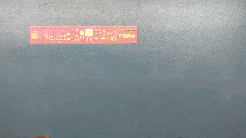
Downloads
PCBWAY
.gif)
.gif)
.gif)

After finalizing the PCBs (Both Rectangular board and square), I send both PCBs to PCBWAY for samples.
I choose white soldermask with Black Silkscreen for both PCBs and placed the order separately.
After waiting for a week, PCBs arrived and their quality was super good.
Overall, there was no error whatsoever and these PCBs that I made were complex, especially the one that contains Voronoi patterns.
Loved how each detail I made in this PCB was proper and perfect.
Check out PCBWAY for getting great PCB service for less cost!
MAIN ASSEMBLY
The main assembly contains the following process-
- Solder paste Dispensing for Square Main MCU PCB
- Pick & place process for the same PCB
- Hotplate reflow
- Switch and connector PCB assembly
- RGB LED Alteration Details
- Attiny85 Flashing Process
- Rectangular Board Main assembly
Removing Conjoined PCBs
.gif)
.gif)
Now before starting the solder paste process, I removed the conjoined Square and rectangular PCB Boards Jointed by an FR4 part by using a cutter.
After removing it completely and making the square PCB surface smooth, I applied solder paste to each component Pad one by one.
Solder Paste Dispensing
.gif)
Solder Paste, if you don't know, is a mixture of tiny solder balls and flux, because solder balls are tiny, this mixture looks and feels like a paste.
We apply solder paste with a solder paste dispenser syringe or the proper method is to use stencil here which I don't have. but anyway, after this, we can now move on to the next process, which is to add components to each pad.
Pick & Place Process
.gif)
Next, we carefully pick all the components with an ESD tweezer and place them in their assigned place one by one.
Hotplate Reflow
.gif)
.gif)
Then after doing the pick and place process, we carefully lifted the whole PCB and place it on the hotplate. I’m using my good old DIY hotplate which I made a few months ago.
Basically, in this hotplate reflow process, the surface heats up to the solder paste melting temp and it slowly melts. after a few mins when the solder paste completely melts, we remove the PCB and let it cool down for a moment.
Switch and Connector PCB Assembly
.gif)
.gif)
I then added SMD Button and UC202 connector manually with help of a soldering iron.
RGB LED Alteration Details
.gif)

.gif)
.gif)
Here's one mistake I made during the PCB Designing process.
This was supposed to be the footprint for 5050 WS2812 LEDs but I accidentally used a different footprint which means I can no longer add SMD RGB LED onto the mainboard.
This was not a problem as I already had a similar RGB Setup with me that I made a few weeks ago.
I added my Previous RGB Matrix on the bottom, side of the square PCB that will face inwards. This matrix contains 64 WS2812 LEDs that are in the 2020 package which is crazy small.
I made the necessary connections and prepared the Attiny85 for its first test run, but before that, we need to burn sweet sweet code in it.
CODE

In this project, I used two codes, one is the popular Fast LED Test sketch and the other one is a custom sketch I made that triggers LED Color on the press of a button.
Here's the test sketch that I used first-
#include <FastLED.h>

#define LED_PIN     0
#define NUM_LEDS    64
#define BRIGHTNESS  64
#define LED_TYPE    WS2811
#define COLOR_ORDER GRB
CRGB leds[NUM_LEDS];

#define UPDATES_PER_SECOND 100

// This example shows several ways to set up and use 'palettes' of colors
// with FastLED.
//
// These compact palettes provide an easy way to re-colorize your
// animation on the fly, quickly, easily, and with low overhead.
//
// USING palettes is MUCH simpler in practice than in theory, so first just
// run this sketch, and watch the pretty lights as you then read through
// the code.  Although this sketch has eight (or more) different color schemes,
// the entire sketch compiles down to about 6.5K on AVR.
//
// FastLED provides a few pre-configured color palettes, and makes it
// extremely easy to make up your own color schemes with palettes.
//
// Some notes on the more abstract 'theory and practice' of
// FastLED compact palettes are at the bottom of this file.


CRGBPalette16 currentPalette;
TBlendType    currentBlending;

extern CRGBPalette16 myRedWhiteBluePalette;
extern const TProgmemPalette16 myRedWhiteBluePalette_p PROGMEM;


void setup() {
    delay( 3000 ); // power-up safety delay
    FastLED.addLeds<LED_TYPE, LED_PIN, COLOR_ORDER>(leds, NUM_LEDS).setCorrection( TypicalLEDStrip );
    FastLED.setBrightness(  BRIGHTNESS );

    currentPalette = RainbowColors_p;
    currentBlending = LINEARBLEND;
}


void loop()
{
    ChangePalettePeriodically();

    static uint8_t startIndex = 0;
    startIndex = startIndex + 1; /* motion speed */

    FillLEDsFromPaletteColors( startIndex);

    FastLED.show();
    FastLED.delay(1000 / UPDATES_PER_SECOND);
}

void FillLEDsFromPaletteColors( uint8_t colorIndex)
{
    uint8_t brightness = 255;

    for( int i = 0; i < NUM_LEDS; ++i) {
        leds[i] = ColorFromPalette( currentPalette, colorIndex, brightness, currentBlending);
        colorIndex += 3;
    }
}


// There are several different palettes of colors demonstrated here.
//
// FastLED provides several 'preset' palettes: RainbowColors_p, RainbowStripeColors_p,
// OceanColors_p, CloudColors_p, LavaColors_p, ForestColors_p, and PartyColors_p.
//
// Additionally, you can manually define your own color palettes, or you can write
// code that creates color palettes on the fly.  All are shown here.

void ChangePalettePeriodically()
{
    uint8_t secondHand = (millis() / 1000) % 60;
    static uint8_t lastSecond = 99;

    if( lastSecond != secondHand) {
        lastSecond = secondHand;
        if( secondHand ==  0)  { currentPalette = RainbowColors_p;         currentBlending = LINEARBLEND; }
        if( secondHand == 10)  { currentPalette = RainbowStripeColors_p;   currentBlending = NOBLEND;  }
        if( secondHand == 15)  { currentPalette = RainbowStripeColors_p;   currentBlending = LINEARBLEND; }
        if( secondHand == 20)  { SetupPurpleAndGreenPalette();             currentBlending = LINEARBLEND; }
        if( secondHand == 25)  { SetupTotallyRandomPalette();              currentBlending = LINEARBLEND; }
        if( secondHand == 30)  { SetupBlackAndWhiteStripedPalette();       currentBlending = NOBLEND; }
        if( secondHand == 35)  { SetupBlackAndWhiteStripedPalette();       currentBlending = LINEARBLEND; }
        if( secondHand == 40)  { currentPalette = CloudColors_p;           currentBlending = LINEARBLEND; }
        if( secondHand == 45)  { currentPalette = PartyColors_p;           currentBlending = LINEARBLEND; }
        if( secondHand == 50)  { currentPalette = myRedWhiteBluePalette_p; currentBlending = NOBLEND;  }
        if( secondHand == 55)  { currentPalette = myRedWhiteBluePalette_p; currentBlending = LINEARBLEND; }
    }
}

// This function fills the palette with totally random colors.
void SetupTotallyRandomPalette()
{
    for( int i = 0; i < 16; ++i) {
        currentPalette[i] = CHSV( random8(), 255, random8());
    }
}

// This function sets up a palette of black and white stripes,
// using code.  Since the palette is effectively an array of
// sixteen CRGB colors, the various fill_* functions can be used
// to set them up.
void SetupBlackAndWhiteStripedPalette()
{
    // 'black out' all 16 palette entries...
    fill_solid( currentPalette, 16, CRGB::Black);
    // and set every fourth one to white.
    currentPalette[0] = CRGB::White;
    currentPalette[4] = CRGB::White;
    currentPalette[8] = CRGB::White;
    currentPalette[12] = CRGB::White;

}

// This function sets up a palette of purple and green stripes.
void SetupPurpleAndGreenPalette()
{
    CRGB purple = CHSV( HUE_PURPLE, 255, 255);
    CRGB green  = CHSV( HUE_GREEN, 255, 255);
    CRGB black  = CRGB::Black;

    currentPalette = CRGBPalette16(
                                   green,  green,  black,  black,
                                   purple, purple, black,  black,
                                   green,  green,  black,  black,
                                   purple, purple, black,  black );
}


// This example shows how to set up a static color palette
// which is stored in PROGMEM (flash), which is almost always more
// plentiful than RAM.  A static PROGMEM palette like this
// takes up 64 bytes of flash.
const TProgmemPalette16 myRedWhiteBluePalette_p PROGMEM =
{
    CRGB::Red,
    CRGB::Gray, // 'white' is too bright compared to red and blue
    CRGB::Blue,
    CRGB::Black,

    CRGB::Red,
    CRGB::Gray,
    CRGB::Blue,
    CRGB::Black,

    CRGB::Red,
    CRGB::Red,
    CRGB::Gray,
    CRGB::Gray,
    CRGB::Blue,
    CRGB::Blue,
    CRGB::Black,
    CRGB::Black
};


// Additional notes on FastLED compact palettes:
//
// Normally, in computer graphics, the palette (or "color lookup table")
// has 256 entries, each containing a specific 24-bit RGB color.  You can then
// index into the color palette using a simple 8-bit (one byte) value.
// A 256-entry color palette takes up 768 bytes of RAM, which on Arduino
// is quite possibly "too many" bytes.
//
// FastLED does offer traditional 256-element palettes, for setups that
// can afford the 768-byte cost in RAM.
//
// However, FastLED also offers a compact alternative.  FastLED offers
// palettes that store 16 distinct entries, but can be accessed AS IF
// they actually have 256 entries; this is accomplished by interpolating
// between the 16 explicit entries to create fifteen intermediate palette
// entries between each pair.
//
// So for example, if you set the first two explicit entries of a compact
// palette to Green (0,255,0) and Blue (0,0,255), and then retrieved
// the first sixteen entries from the virtual palette (of 256), you'd get
// Green, followed by a smooth gradient from green-to-blue, and then Blue.
This was the main Sketch- it's based around Adafruit's neopixel library so you need to download that before using this sketch.
#include <Adafruit_NeoPixel.h>

#define BUTTON_PIN   4
#define PIXEL_PIN   0   // Digital IO pin connected to the NeoPixels.

#define PIXEL_COUNT 64

Adafruit_NeoPixel strip = Adafruit_NeoPixel(PIXEL_COUNT, PIXEL_PIN, NEO_GRB + NEO_KHZ800);

bool oldState = HIGH;
int showType = 0;

void setup() {
  pinMode(BUTTON_PIN, INPUT_PULLUP);
  strip.begin();
  strip.show(); // Initialize all pixels to 'off'
}

void loop() {
  // Get current button state.
  bool newState = digitalRead(BUTTON_PIN);

  // Check if state changed from high to low (button press).
  if (newState == LOW && oldState == HIGH) {
    // Short delay to debounce button.
    delay(20);
    // Check if button is still low after debounce.
    newState = digitalRead(BUTTON_PIN);
    if (newState == LOW) {
      showType++;
      if (showType > 14)
        showType=0;
      startShow(showType);
    }
  }

  // Set the last button state to the old state.
  oldState = newState;
}


void startShow(int i) {
  switch(i){
    case 0: colorWipe(strip.Color(0, 0, 0), 50);    // Black/off
            break;
    case 1: colorWipe(strip.Color(255, 0, 0), 50);  // Red
            break;
    case 2: colorWipe(strip.Color(0, 255, 0), 50);  // Green
            break;
    case 3: colorWipe(strip.Color(0, 0, 255), 50);  // Blue
            break;
    case 4: colorWipe(strip.Color(100, 0, 255), 50);  // purp
            break;
    case 5: colorWipe(strip.Color(200, 0, 255), 50);  // lite purp
            break;
    case 6: colorWipe(strip.Color(255, 0, 100), 50);  // pink
            break;
    case 7: colorWipe(strip.Color(255, 255, 0), 50);  // yellown
            break;
    case 8: colorWipe(strip.Color(255, 110, 20), 50);  // orange
            break;
    case 9: colorWipe(strip.Color(255, 100, 100), 50);  // Rorange
            break;
    case 10: colorWipe(strip.Color(255, 180, 40), 50);  // lite orange
            break;
    case 11: colorWipe(strip.Color(0, 255, 255), 50);  // LIGHT Blue
            break;
    case 12: colorWipe(strip.Color(0, 255, 100), 50); //greenish blue
            break;
    case 13: colorWipe(strip.Color(150, 255, 0), 50);  //greenish red
            break;
    case 14: colorWipe(strip.Color(255, 255, 255), 50);  // white
            break;
  }
}


void colorWipe(uint32_t c, uint8_t wait) {
  for(uint16_t i=0; i<strip.numPixels(); i++) {
    strip.setPixelColor(i, c);
    strip.show();
    delay(wait);
  }
}
ATTINY85

Now here's one of the best examples of how a simple 1$ Chip can run stuff like an Arduino board without using a bunch of componenets and other stuff.
Attiny85 is by far one of the best MCU I used, it's not because of its connectivity or features like BT or wifi (It doesn't have those).
It's a low-power Microchip 8-bit AVR® RISC-based microcontroller that combines 8 KB ISP Flash memory, 512B EEPROM, 512B SRAM, six general-purpose I/O lines, 32 general purpose working registers, one 8-bit timer/counter with compare modes, one 8-bit high-speed timer/counter, USI, internal and external Interrupts, 4-channel 10-bit A/D converter, programmable watchdog timer with internal oscillator, three software selectable power saving modes, and debugWIRE for on-chip debugging. The device achieves a throughput of 20 MIPS at 20 MHz and operates between 2.7-and 5.5 volts.
Attiny85 is great because of how well it can do certain things that an Arduino can perform as well but in a smaller much more user-friendly form factor. we can implement it into any kind of project and it will work smoothly.
I've been using it for the past 5 years and I will still use it in the future because of its reliability and the most important factor- cost!.
Flashing the Attiny85
As for the Flashing Process, we cannot directly program ATTINY85 through any USB, I mean there's a method for programming the Attiny straight from the USB port but I'm not doing that.
Instead, I'll be using the ISP flashing method which will utilize the SPI Pins of attiny85 to burn the bootloader in it and then Flash.
To connect the Attiny with the programmer, I used my SOIC clip to which we can directly connect the attiny.
Getting Attiny85 Core Installed on Arduino IDE
Before starting the Flashing process, we first need to download and install the Attiny85 Core files in Arduino IDE.
https://github.com/SpenceKonde/ATTinyCore
- File->Preferences on a PC, or Arduino->Preferences on a Mac, enter the above URL in "Additional Boards Manager URLs
- Tools -> Boards -> Boards Manager... *If using 1.6.6, close boards manager and re-open it (see below)
- Select "ATTinyCore by Spence Konde" and click "Install".
AVRs chips usually come blank, they need to be set up to be Arduino IDE compatible but to do that you need an AVR programmer do to that, for example, a USBASP.
Fun Fact, you could make your own AVR Programer with an Arduino Uno or a Nano board in a very easy step.
- Connect your Arduino board with com port and select the following sketch
- Example>ArduinoISP upload this sketch onto your board
- After uploading, go to the tools menu and choose the Arduino as ISP option in the programmer section.
- Now for flashing Attiny85, we can select the Attiny85 in the Board section.
The programming process uses VCC, GND, and four data pins. Three pins connect MISO, MOSI, and SCK between the programming micro and the target micro, the fourth pin from the programming micro goes to the reset pin of the target.
Wire the Attiny85 with Arduino in the above way. (also right after uploading ISP Sketch to your Arduino, do not forget to add a 10uf Cap between Reset and GND pins of your Arduino board)Instead of using an Arduino UNO and a breadboard for this job, I will use my DIY Attiny Programmer which I made for flashing the Attiny or Atmega MCUs.
which you can check out from here-
https://www.instructables.com/Multiple-ATtiny8513A...
- connect the Board to the Arduino as ISP Setup in the above wiring config
- choose the right port, right programmer (Arduino as ISP), and hit Burn Bootloader
- wait for a few seconds, you will get done burning the bootloader message.
- Now Open the sketch that you want to upload to this AttinyGo to the Sketch menu and select Upload using the programmer.
- and your Sketch will get uploaded onto the attiny85.
Test Sketch Result
.gif)
.gif)
.gif)
.gif)
Here's how well it can drive this 64 LED matrix without any lag.
I'm using a 5V 2A smartphone charger with a Type C Cable for providing its power.
- After Testing the board, I soldered a UC202 wire harness on the switch port of the Main PCB and then connected it with Switch PCB.
- Then I glued the matrix with the main PCB and prepared the LED Section for final soldering or final assembly.
Rectangular Board Main Assembly
.gif)
.gif)
.gif)
.gif)
.gif)
.gif)
.gif)
.gif)
Now after testing the Main MCU working, we can now move on to the final process which is to put everything together and start the assembly process.
- I first added solder wire on one side of the soldering pad
- after placing the Main PCB in its right position, I joined its soldering pad with the soldering pad of the wall PCB. I then added solder wire on another side as well.
- I then placed the switch PCB with the same method in its place and added other wall PCBs on both sides by soldering their pads together.
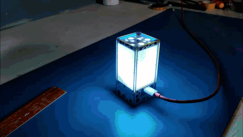
Final Result

.gif)
This was the final result.
By Pressing the button on LID we can change the LED color.
We can add animations and other stuff in this project as well, we just need to alter the code and that is pretty much what we need to do.
Conclusion
.gif)
Voronoi shapes or patterns are visible which was the goal of the entire project.
however, I'm not happy with the lighting effect so I will be making a V2 of this project and correcting some mistakes I made in the Main PCB Design.
This is it for today, Leave a comment if you guys need any help, and I'll be back with another project soon!
Thanks, PCBWAY for supporting this project, Do check PCBWAY for getting great PCB service for less cost!
Peace