Voice Controlled Scooter Lights and Garage Door
by SahilParikh in Circuits > Arduino
712 Views, 4 Favorites, 0 Comments
Voice Controlled Scooter Lights and Garage Door

Hello Everyone!
I recently bought an electric scooter but it didn't have a rear light nor did it have an inbuilt garage door opener...SURPRISE!! (ノ゚0゚)ノ~
So, I decided to make my own garage door remote and rear lights instead of buying them.
What's the fun in having buttons for opening a garage door?! So, I decided to make the whole thing voice controlled. It's more fun to ask the door to open instead of pressing buttons. This works great in terms of functionality and show.
I looked up a few bike lights projects such as https://www.instructables.com/id/Bike-Light-and-Turn-Signals/ and decided to create my own upgraded version. So, I settled to step up my lights to match with my style on my electric scooter by adding animated turn signals. They Also have an nRF24L01 module to wirelessly control the garage door using voice.
The lights are made up of a 16x16 LED Matrix to have animated turn signals.
Please check it out in the video above.
Below are the instructions to make one for yourself.
Gather the Parts
For this instructable you need the following parts:
1: 2x Arduino (I'm using nano)
2: Voice recognition module (I got it at a cheaper deal from eBay)
4: A 5V power source for LED Matrix
5: Another power source of 5V but I'm using 9V
6: 2x nRF24L01 modules
7: Relay module
8: Wires
Connect the Components (bike Unit)
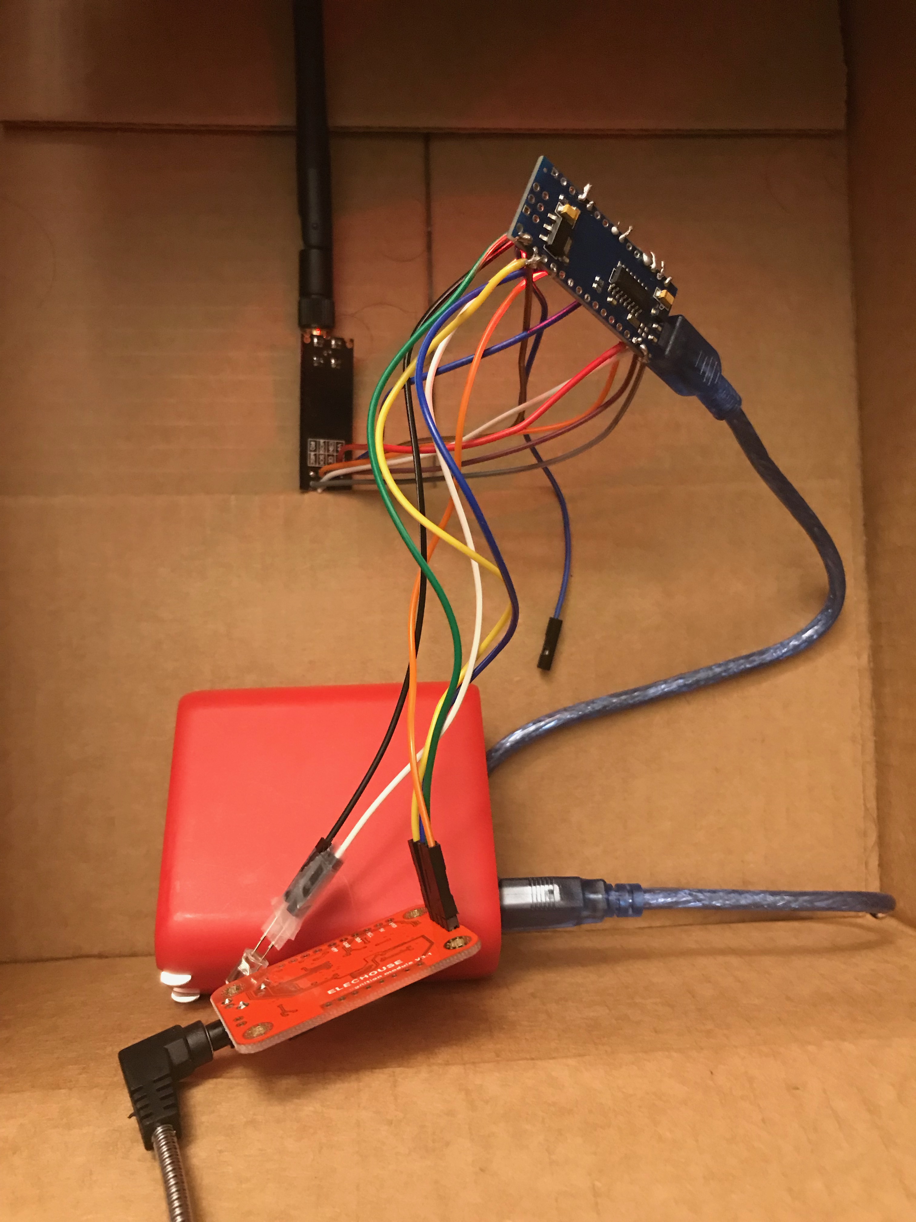
To begin start wiring the Arduino, nRF24L01, speech recognition module, power source, and the LED matrix.
A. Connections for nRF24L01:
-MISO connects to pin 12
-MOSI connects to pin 11
-SCK connects to pin 13
-CE connects to pin 9
-CSN connects to pin 10
-GND and VCC of the NRF24L01 are connected to GND and 3.3V of Arduino
B. Connections for Speech Recognition Module:
-RX connects to pin 6
-TX connects to pin 5
-GND and VCC of the module are connected to GND and 5V of Arduino
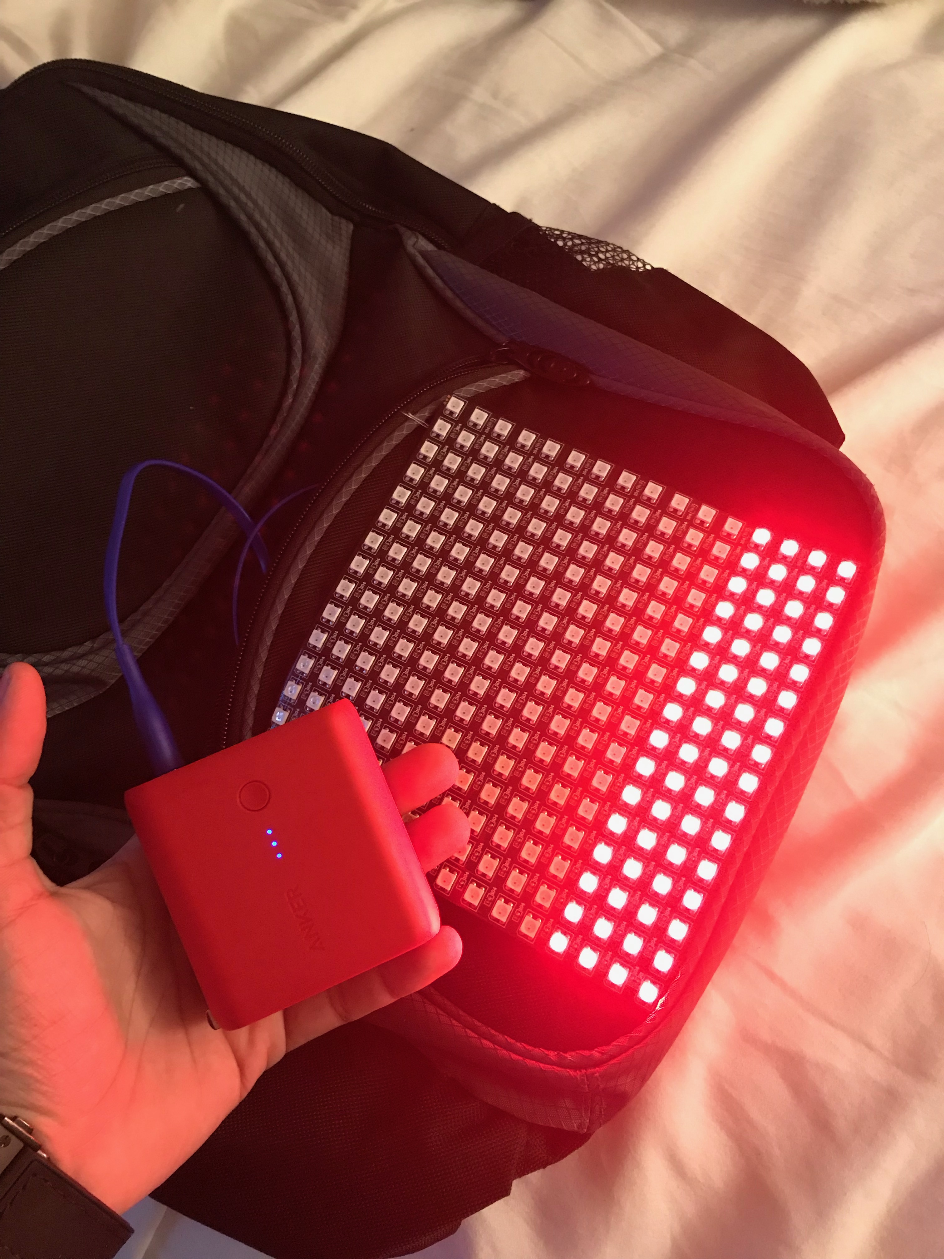
C. Connections for the LED Matrix:
I used a power bank to supply power. To connect a power bank take a USB cable and strip the +ve and -ve ends of the cable.
-5V of the Matrix connects to VIN pin of Arduino and the +ve connection of the power source
-GND of the Matrix connects to GND pin of Arduino and the -ve connection of the power source
Train Voice Module
A. Download the Voice control library.
B. Open file -> Examples -> VoiceRecognitionV3 -> vr_sample_train
i. Modify "VR myVR(2,3);" to "VR myVR(6,5);" in the code to account for RX TX pin change.
ii. Upload the code
C. Open serial monitor
i. Set the baud rate to 115200 and select the "Newline" option.
ii. A menu will open up the guide.
1. Use the "train" command to train speech.
2. Type "train 0", it'll ask you to speak the command and, then ask to say it again.
3. Do the same for "train 1", "train 2", etc.
In the code:
train 0 is to control the garage door
train 1 is the left signal
train 2 is the right signal
train 3 is to turn on red lights
train 4 is to turn off lights
Get the Libraries and Upload the Code
Download additional libraries for LED Matrix and nRF24L01.
A. Go to Sketch -> Include library-> Manage libraries... and install RF24 by TMRh20.
B. Also, install the Neo Pixel library by Adafruit.
C. Upload the attached code ScootSendProtowtlightsIns.ino.
The code has comments for an explanation but it's very straight forward.
Downloads
Connect the Components (garage Unit)
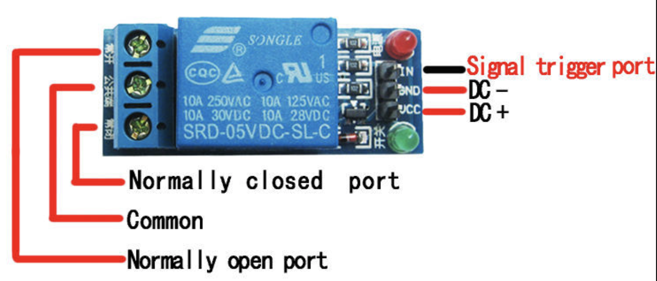
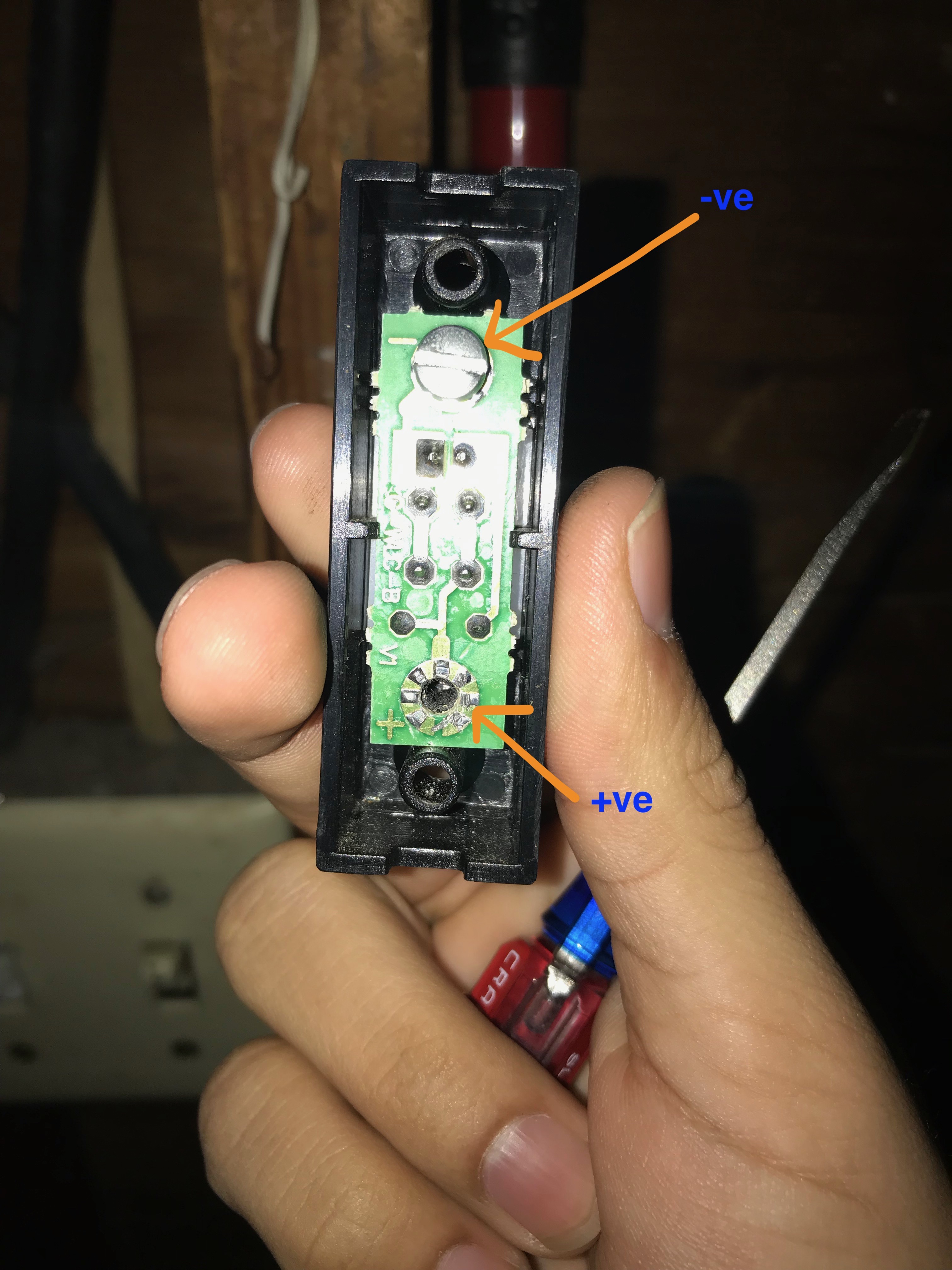
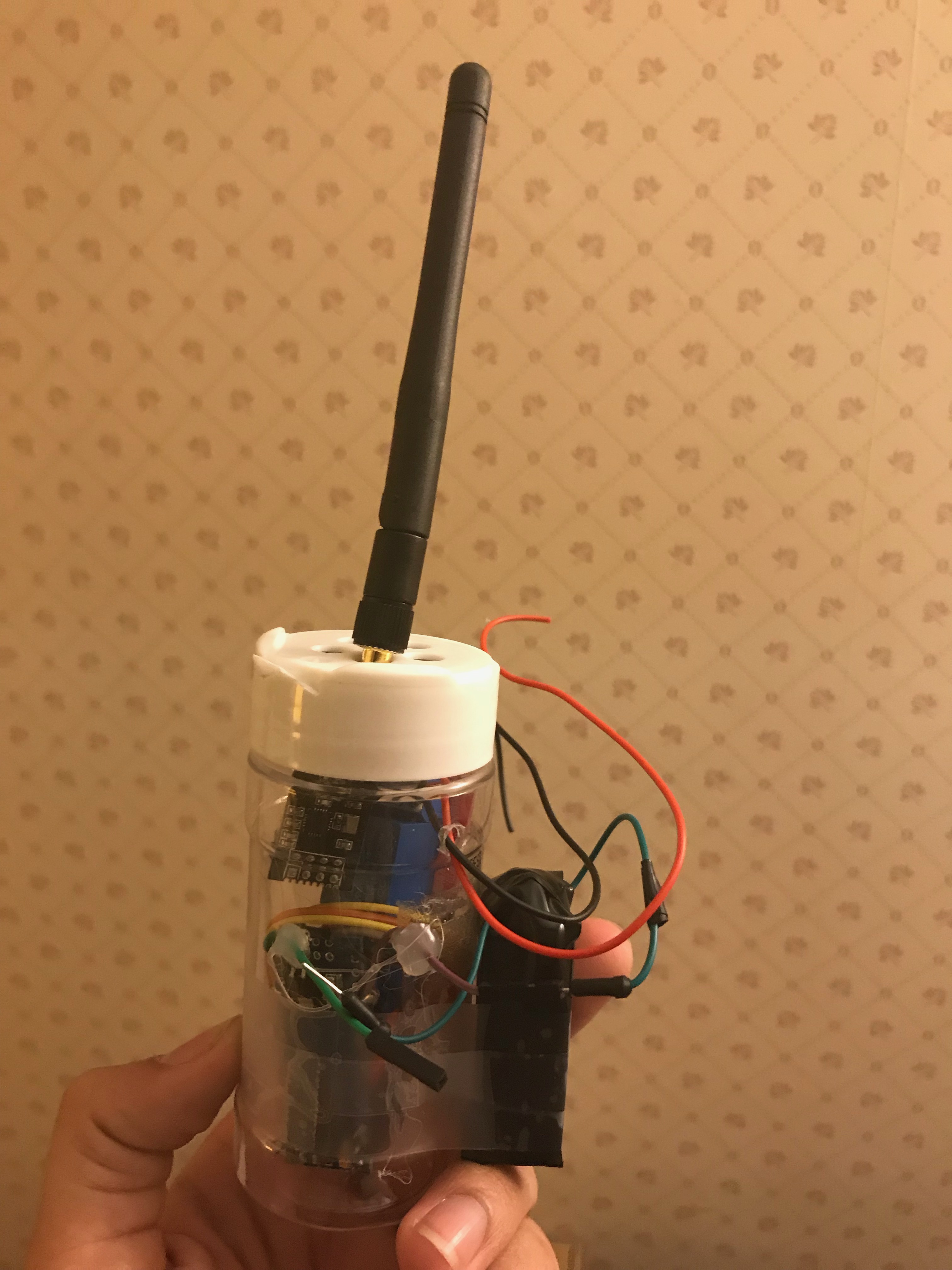
For the garage door unit, we need to wire the relay module, nRF24L01, power source, and Arduino.
I created the entire assembly in a salt dispenser bottle.
A. Connections for nRF24L01:
MISO connects to pin 12
MOSI connects to pin 11
SCK connects to pin 13
CE connects to pin 9
CSN connects to pin 10
GND and VCC of the NRF24L01 are connected to GND and 3.3V of Arduino
B. Connections for relay module:
DC- and DC+ of the relay module are connected to GND and 5V of Arduino
The signal trigger port connects to pin 2 of Arduino
Connect one end of the switch to the common port of the relay
Connect the other end of the switch to the normally closed port of the relay
C. Connections for power source:
Connect the 9V battery's +ve end to the VIN pin of Arduino
Connect the -ve end to the GND pin of Arduino
D. Upload the code
Downloads
Test and Travel in Style
Demo video was attached at the top of the instructable.
Hope you liked the instructable. Comment if you have any questions.
You can add more animations to the LED matrix. You can also control things other than the garage door.
Surprisingly, the speech recognition works well even when at speeds of 15 mph.
Please Vote for it.
Thank you,
Sahil Parikh