Voice Activated Home App
by kannan uday in Circuits > Remote Control
480 Views, 14 Favorites, 0 Comments
Voice Activated Home App

Control your Arduino with voice commands using an Android smartphone! Before we make a voice activated home automation system, we must first learn the basic principles of the experiment. This guide will let you command the Arduino using your Android smartphone and a HC-05 Bluetooth module.The designer of the app did not include a sample code. I looked for alternatives in Google's PlayStore but none was as good as the app that I've found. Luckily, I was able to figure it out although it took me a while to program it. Sorry IOS users, this app isn't available in Apple's app store :/How Does It Work?Have you ever encountered Android's speech recognition? Yes android has one and you can use it to control your Arduino, via Bluetooth. The App works by pressing the mic button, then the it will wait for you to say a command. The app will then display the word's that you've stated and will send data strings for the Arduino to process. Home Automation System :A month from now/ I'll be releasing a highly sophisticated home automation + security system. It's my biggest project ever! Our current agenda is to program a better smartphone app that work's like Siri (talks back) and sends strings (data types) to the Arduino via bluetooth. If you want to take a sneak peek of the project and it's concept, kindly skip to the last step. The prototype that I'm working on now is composed of a network of wireless switch boxes that connects to a main control panel via WiFi/ Bluetooth.
Purchase
If your having trouble in finding them, I'm sure RadioShack has all of them. If you want to buy online try searching on Amazon or DealExtreme.
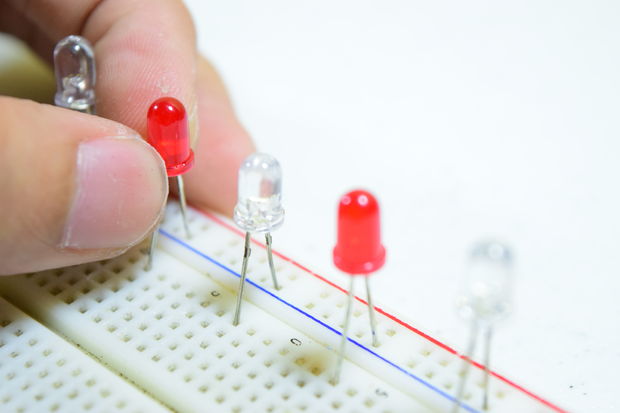
Thing that you'll need:- 5 LED Indicators (the color of your choice)- Arduino UNO (a clone works fine)- HC-05 Serial Bluetooth Module- Solderless Breadboard- Jumper Cables
Assemble

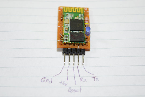
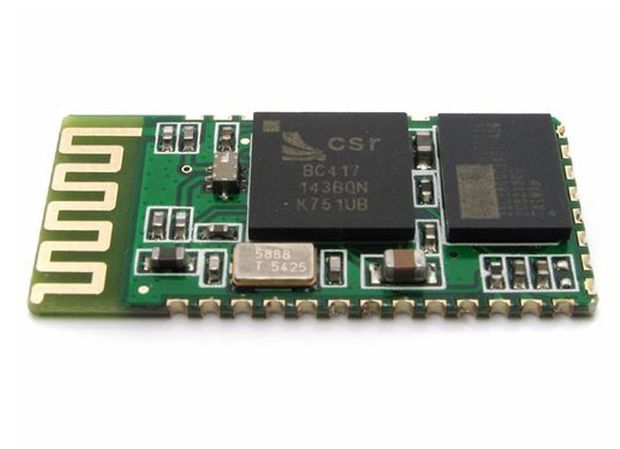
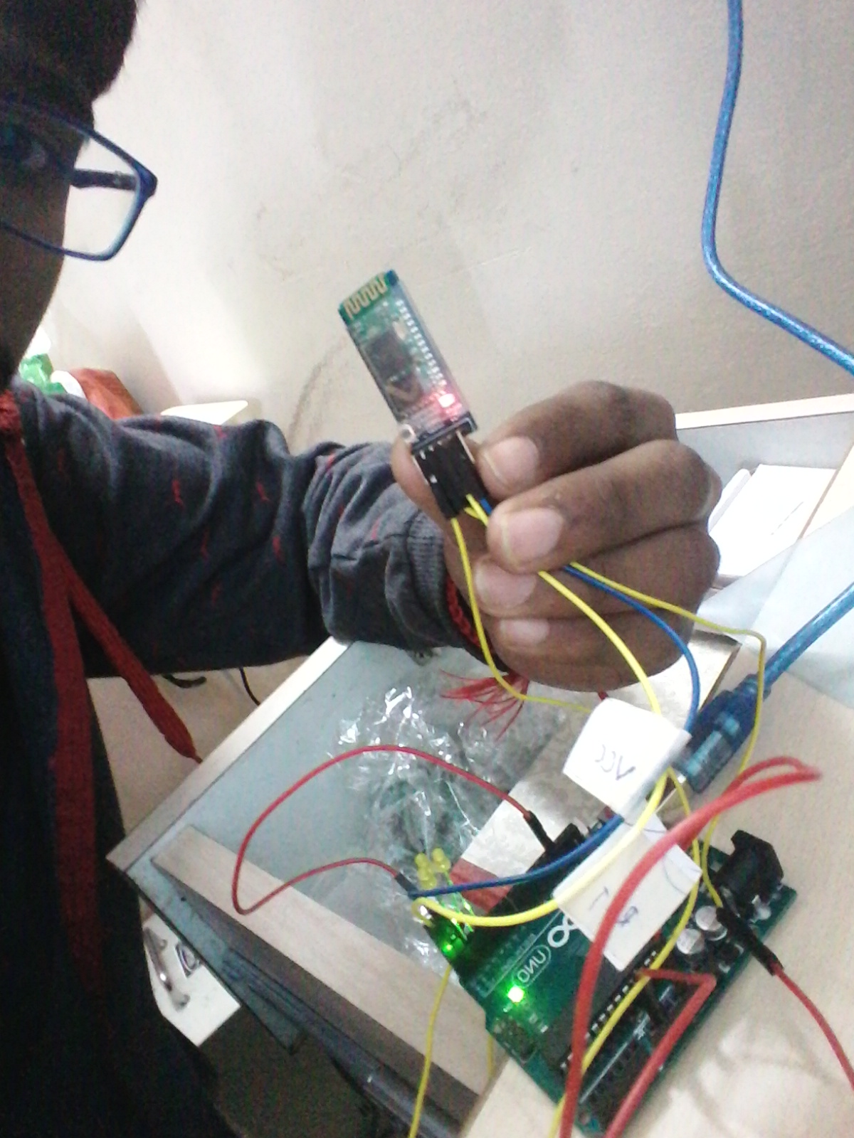
My JY-MCU (DX Bluetooth Module) is still installed on my robots, what I have right now is the bare HC-05 module.As we all know, the HC-05 doesn't come with a PCB. Soldering wires, directly to the metal conductors, isn't a good idea since the conductors could chip off anytime. As a solution, you can cut a fraction of perf-board then mount the HC-05 on it. I mistakenly connected my LED indicator on a blank (N/A) pin so mine doesn't work.___________________________________________Too lazy to assemble a Bluetooth shield? DX.com has a ready made version (click here). I've used the DX Bluetooth module on my robots, it's tested and it's 100% ok! You can visit Bluetooth related projects (Bluetooth Sumobot and Bluetooth FPV Rover) as reference.
Led Placing

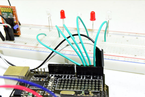
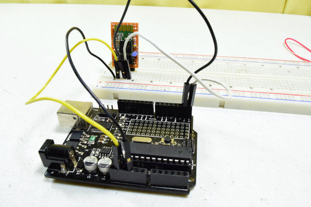
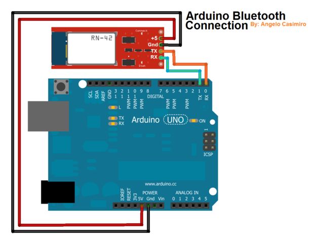
Grab some jumper cables and power the Bluetooth module with 3.3 volts. Remember, the bare HC-05 run on 3.3v and not on 5v. On the other hand, the JY-MCU has a built in regulator, it can run on a 5v line.Now connect the RX (pin #0) of the Arduino to the TX pin of the Bluetooth module and the TX (pin #1) of the Arduino to the RX pin of the Bluetooth module. (refer to the image above)
Connect the positive leads of each LED on pins # 2,3,4,5,6 of the Arduino. The negative leads of each LED goes to the negative rail of the breadboard. The negative rail of the breadboard goes to the Arduino's ground.
Application
Understanding The App: Before you program the arduino, you must first learn how the app works. The app work by recognizing your voice command, it will then display the words that you've spoken then sending data/ strings to the arduino via bluetooth. What's a string? A string is like a word, you can make conditional statements out of it [ex: if (voice == "*computer on") {// turn Pin #2 on} ]. The "voice" is your string, "==" is your condition (means equal to), "*computer on" is your command and the code inside the curly-braces "{ }" are the codes to be executed once your string matches the command condition. What's the format of the string? How does it know when the next command kicks in? How does it differentiate a set of words from a new command? The app sends strings in this format *command#, the asterisk (*) indicates the start of a new command and the hash-tag (#) indicates the end of a command. I was able to remove the hash-tag (#) after each word in the conditional statement was not able to remove the asterisk (*). You'll need to start your command condition with an asterisk otherwise the sketch will not work. How Can I Change The Commands?You can see that the "*TV on" is highlighted from the image above. If you want to change the command to ,humm let's say "open garage door", you can replace the "*TV on" with "*open garage door". Always remember to start the command with an asterisk.
Steps

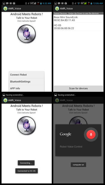
Steps:1st.) Download the app from Google PlayStore2nd.) Tap on options menu then select "Connect Robot"3rd.) Click on your BT-Module (in my case it's the HC-05)4th.) Wait until it says Connected to BT-Module (HC-05)5th.) Tap on the mic icon and state your command!
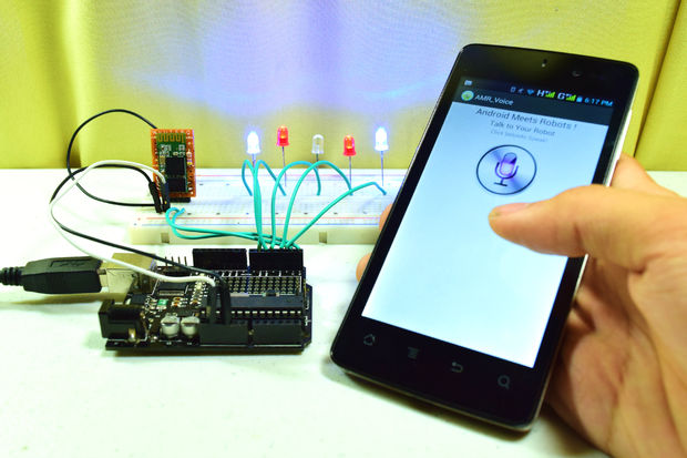
My Proof,

Download The Free App Here: Android Meets Robots : Voice
//Coded By: udaya kumar 1/13/2018
//Voice Activated Arduino (Bluetooth + Android) //Feel free to modify it but remember to give credit
String voice; int led1 = 2; //Connect LED 1 To Pin #2 int led2 = 3; //Connect LED 2 To Pin #3 int led3 = 4; //Connect LED 3 To Pin #4 int led4 = 5; //Connect LED 4 To Pin #5 int led5 = 6; //Connect LED 5 To Pin #6 //--------------------------Call A Function-------------------------------// void allon(){ digitalWrite(led1, HIGH); digitalWrite(led2, HIGH); digitalWrite(led3, HIGH); digitalWrite(led4, HIGH); digitalWrite(led5, HIGH); } void alloff(){ digitalWrite(led1, LOW); digitalWrite(led2, LOW); digitalWrite(led3, LOW); digitalWrite(led4, LOW); digitalWrite(led5, LOW); } //-----------------------------------------------------------------------// void setup() { Serial.begin(9600); pinMode(led1, OUTPUT); pinMode(led2, OUTPUT); pinMode(led3, OUTPUT); pinMode(led4, OUTPUT); pinMode(led5, OUTPUT); } //-----------------------------------------------------------------------// void loop() { while (Serial.available()){ //Check if there is an available byte to read delay(10); //Delay added to make thing stable char c = Serial.read(); //Conduct a serial read if (c == '#') {break;} //Exit the loop when the # is detected after the word voice += c; //Shorthand for voice = voice + c } if (voice.length() > 0) { Serial.println(voice); //-----------------------------------------------------------------------// //----------Control Multiple Pins/ LEDs----------// if(voice == "*all on") {allon();} //Turn Off All Pins (Call Function) else if(voice == "*all off"){alloff();} //Turn On All Pins (Call Function) //----------Turn On One-By-One----------// else if(voice == "*TV on") {digitalWrite(led1, HIGH);} else if(voice == "*fan on") {digitalWrite(led2, HIGH);} else if(voice == "*computer on") {digitalWrite(led3, HIGH);} else if(voice == "*bedroom lights on") {digitalWrite(led4, HIGH);} else if(voice == "*window lights on") {digitalWrite(led5, HIGH);} //----------Turn Off One-By-One----------// else if(voice == "*TV off") {digitalWrite(led1, LOW);} else if(voice == "*fan off") {digitalWrite(led2, LOW);} else if(voice == "*computer off") {digitalWrite(led3, LOW);} else if(voice == "*bedroom lights off") {digitalWrite(led4, LOW);} else if(voice == "*window lights off") {digitalWrite(led5, LOW);} //-----------------------------------------------------------------------// voice="";}} //Reset the variable after initiating