Vision AI: Rock-Paper-Scissors on ESP32 CYD
by CLClab306 in Circuits > Sensors
1211 Views, 3 Favorites, 0 Comments
Vision AI: Rock-Paper-Scissors on ESP32 CYD
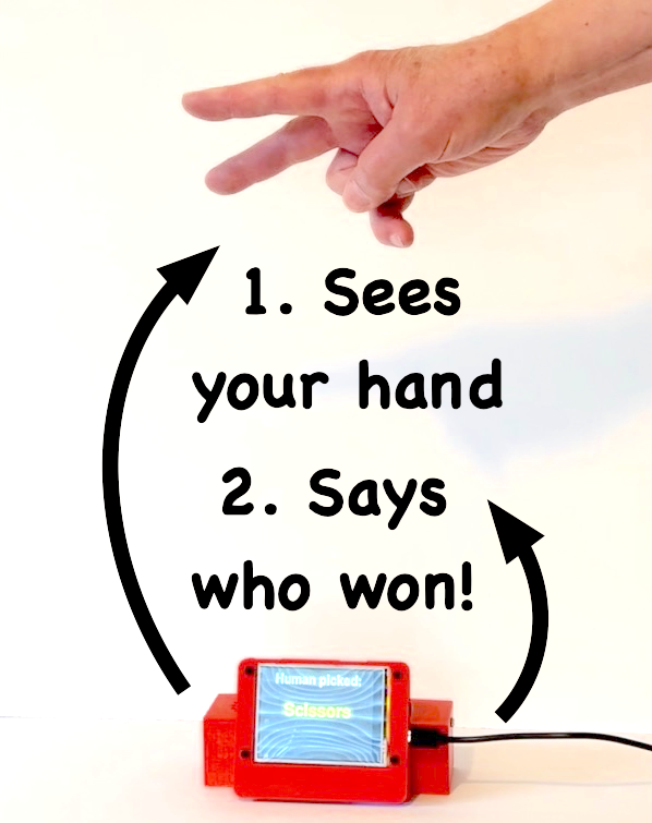
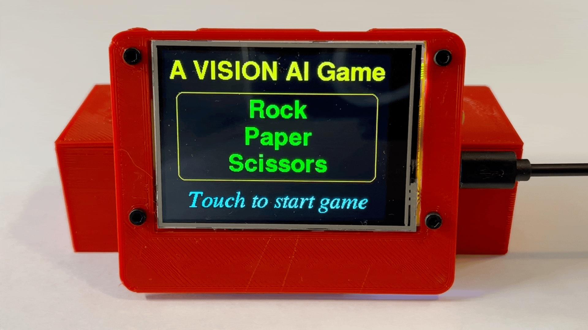
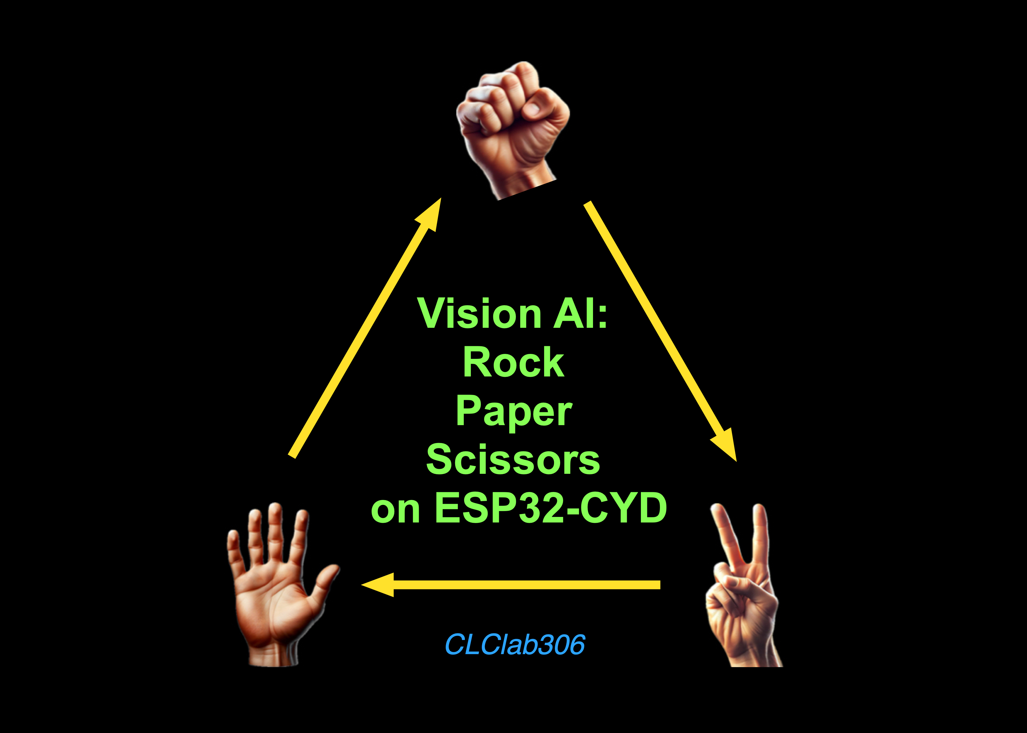
This Instructable shows how to create a non-human opponent for the Rock-Paper-Scissors game using the Grove Vision AI Module V2 and the ESP32-2432S028R development board, better known as the "Cheap Yellow Display" or CYD. In addition to visual feedback from the CYD, the human player receives audio feedback from a DFPlayer Mini MP3 Player and speaker. Importantly, after the Gesture Detection Model has been flashed onto the Grove Vision AI Module, the game can be played anywhere, with no need to connect to an external server over WiFi.
This project provides information about: (a) using the Grove Vision AI module, (b) using the CYD's built-in micro-SD card reader to display images, and (c) using the CYD's extended I/O pins to communicate with other devices like the Vision AI Module and DFPlayer Mini. It is directed primarily toward those who are interested in learning more about how to integrate these components into one device.
In the interest of full disclosure, although the non-human opponent is referred to as "AI" in this game, the only ongoing role artificial intelligence plays is in using Vision AI to categorize the human player's hand gestures as rock, paper or scissors. The non-human opponent's choices are completely random (using the ESP32's esp_random function), not the result of an explicit AI-assisted strategy. That said, the programing could easily be modified to give the non-human opponent a non-random strategy (e.g., win-stay, lose-shift).
This project requires soldering and familiarity using the Arduino IDE to load program sketches on the ESP32 microcontroller.
Supplies
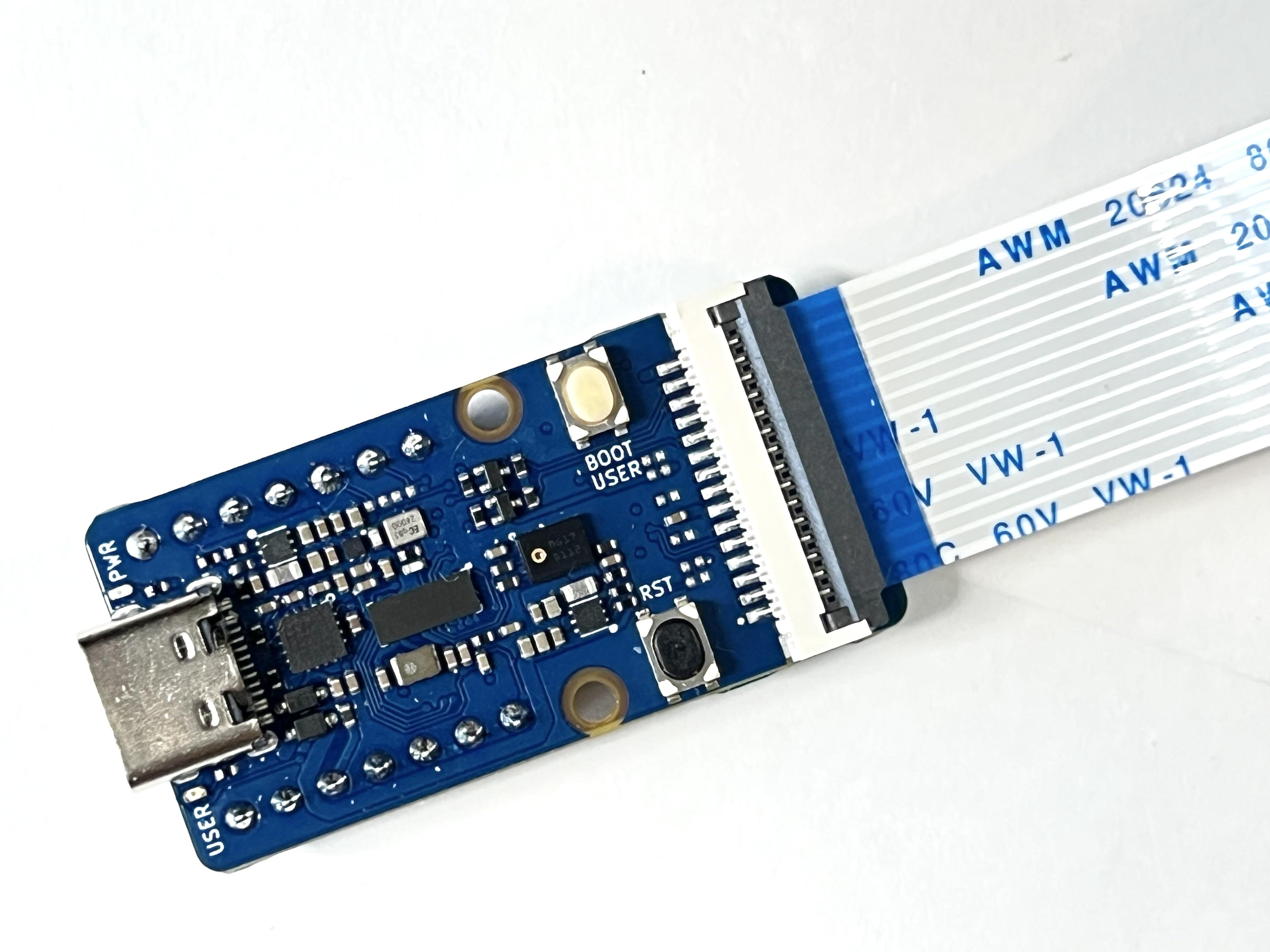
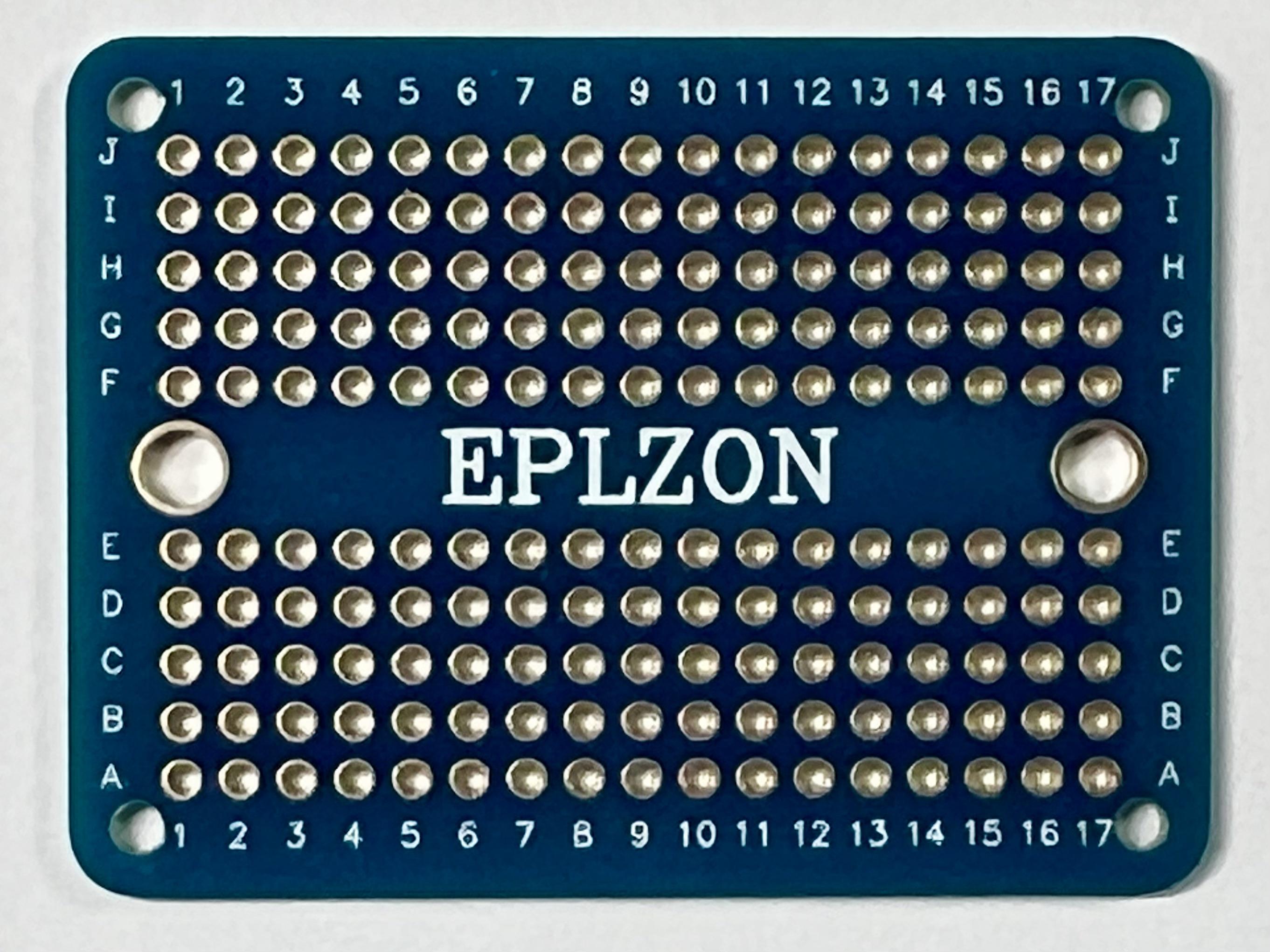
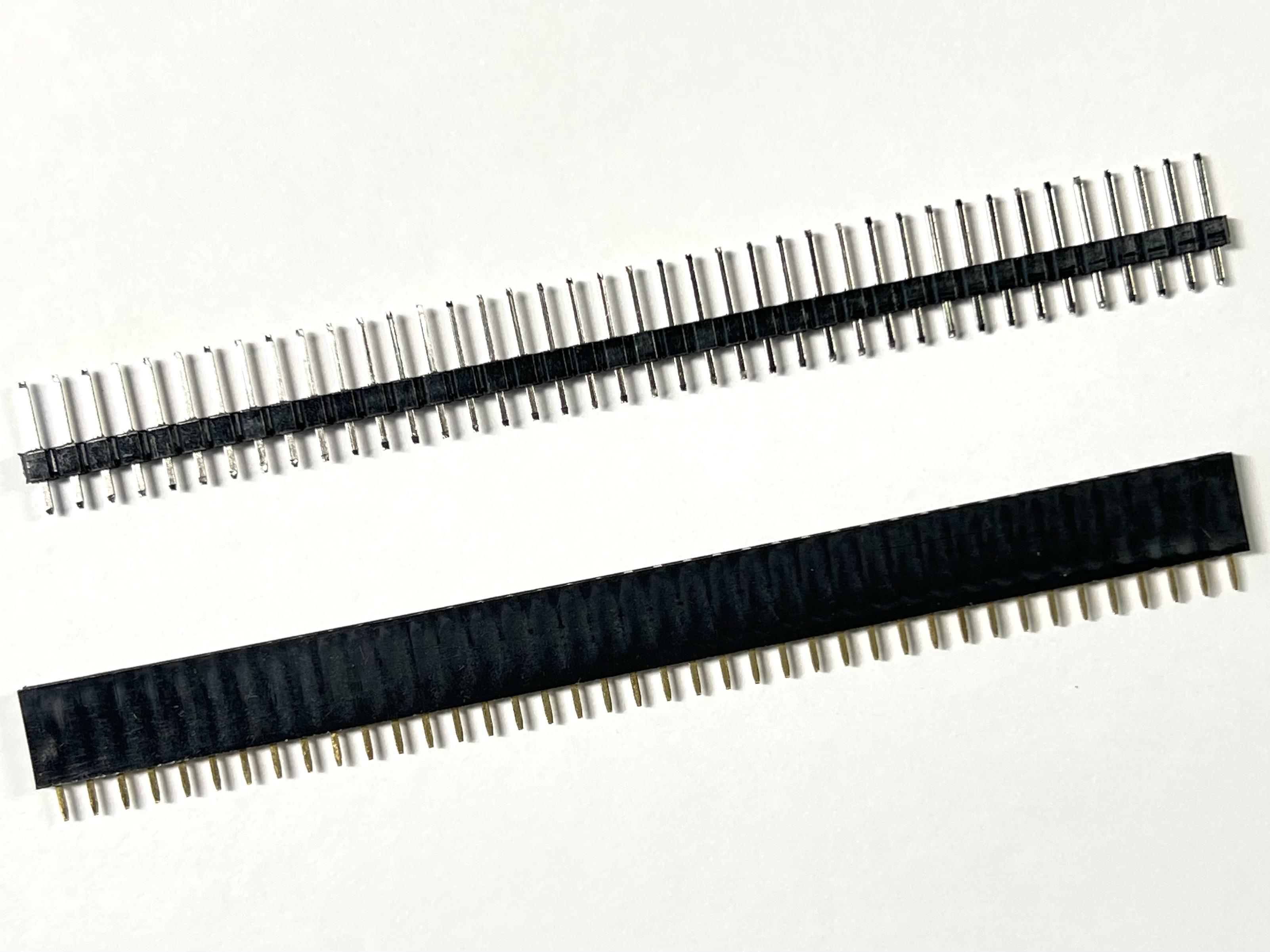
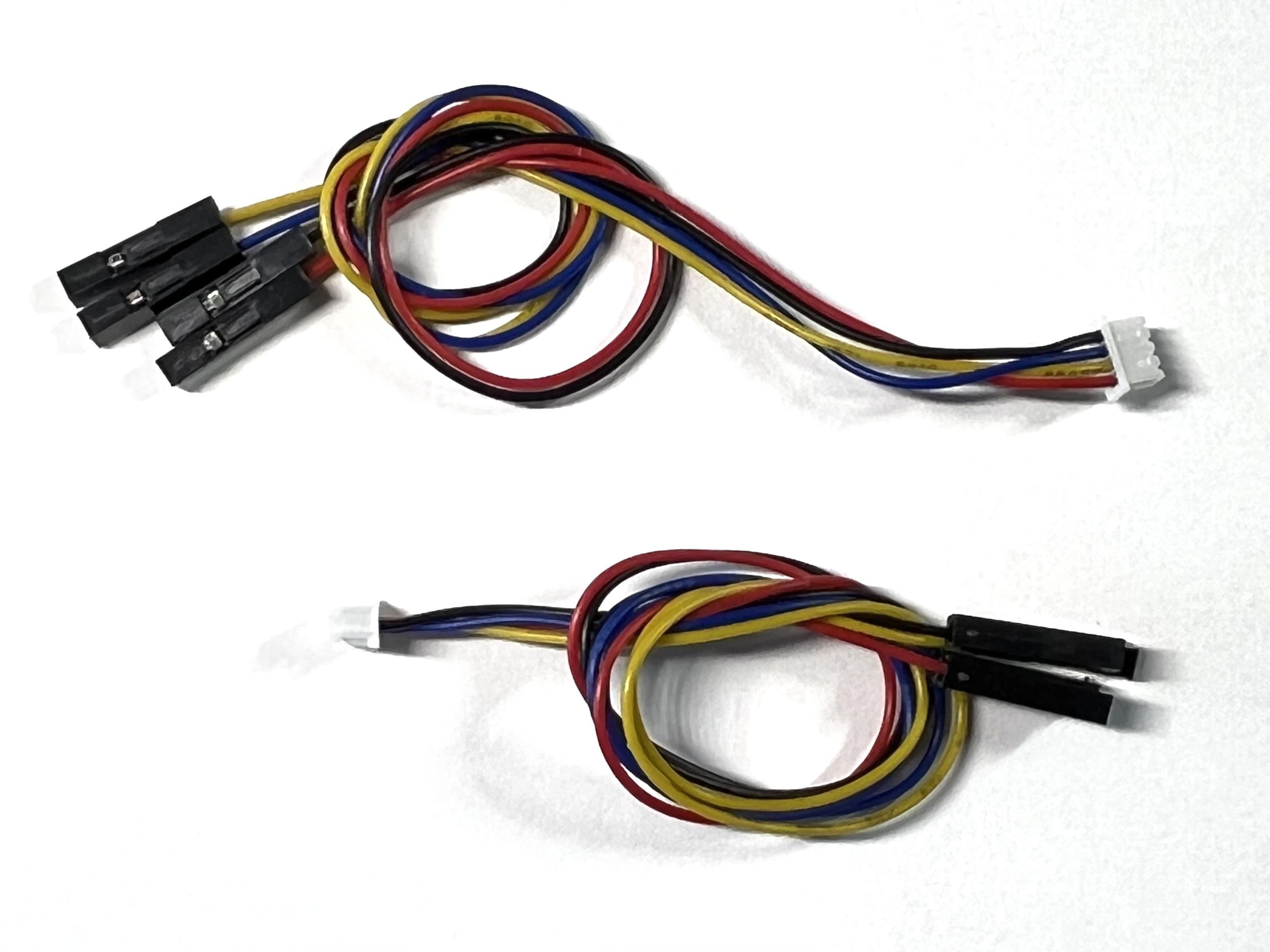
- Grove Vision AI Module V2 (~$15.99)
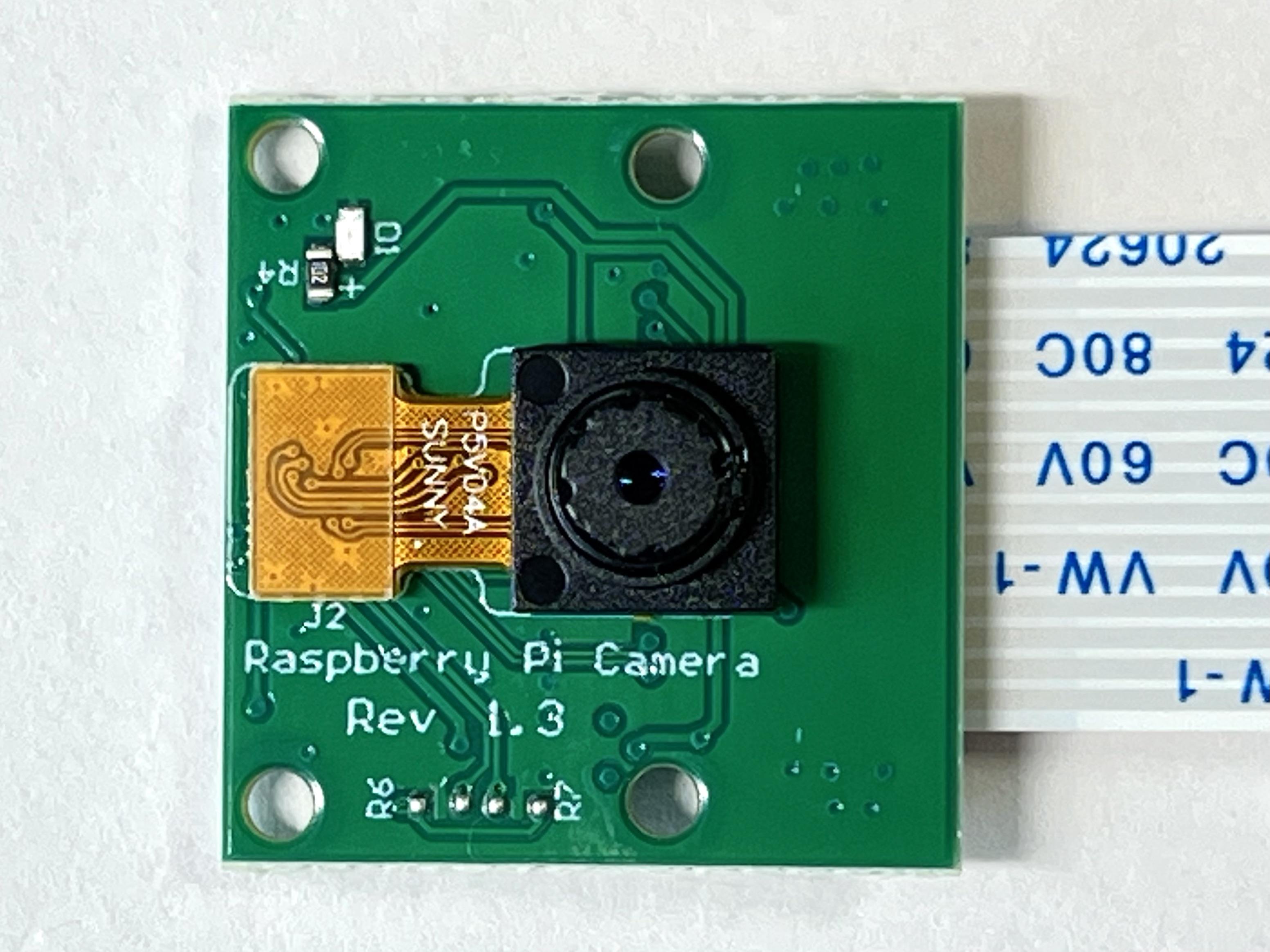
- OV5647-62 FOV Camera Module (~$7.90 each)
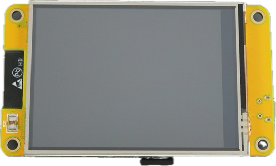
- ESP32-2432S028R (CYD) (~$12.39 each)
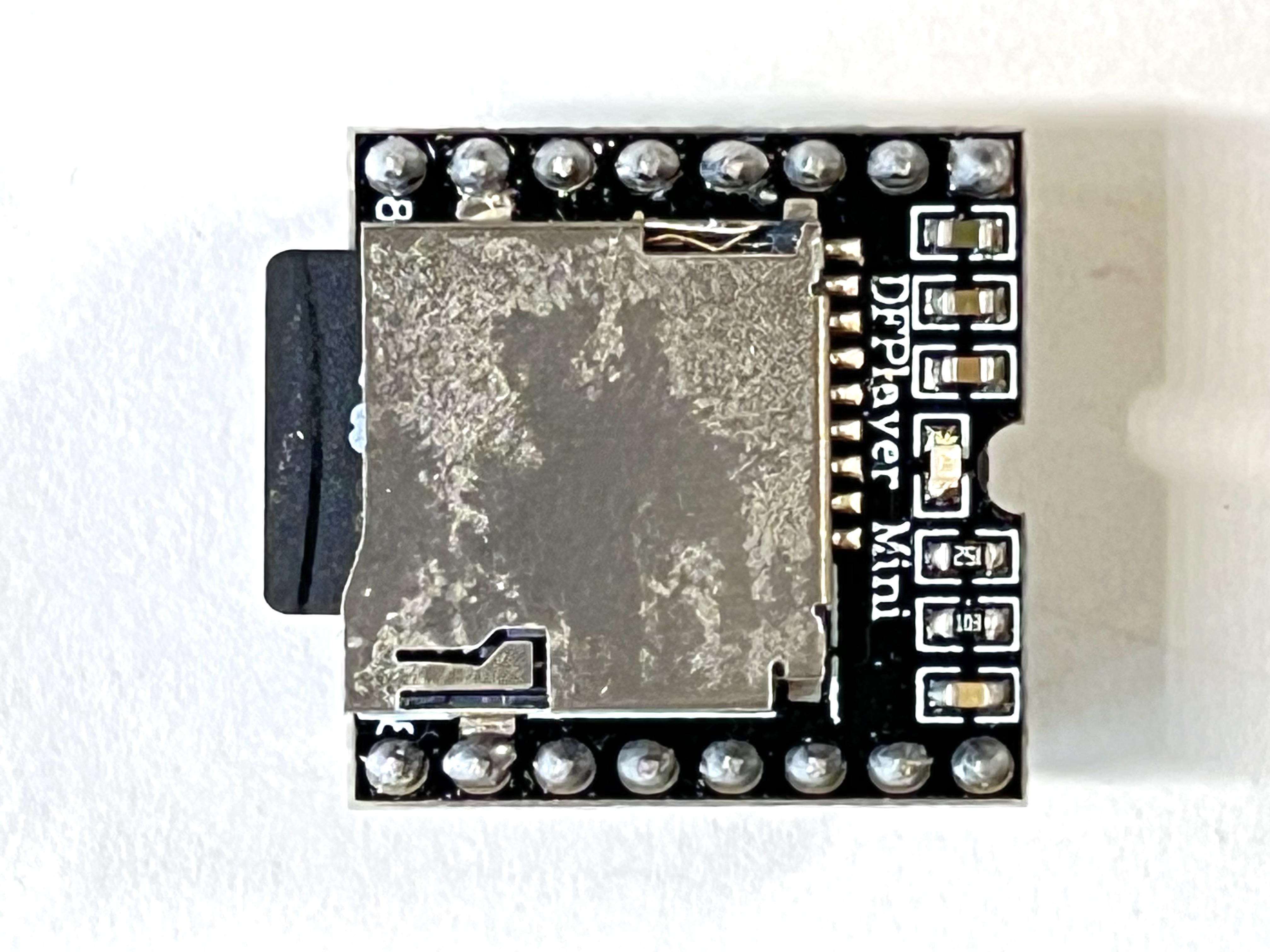
- DFPlayer Mini MP3 player (~$5.90 each)
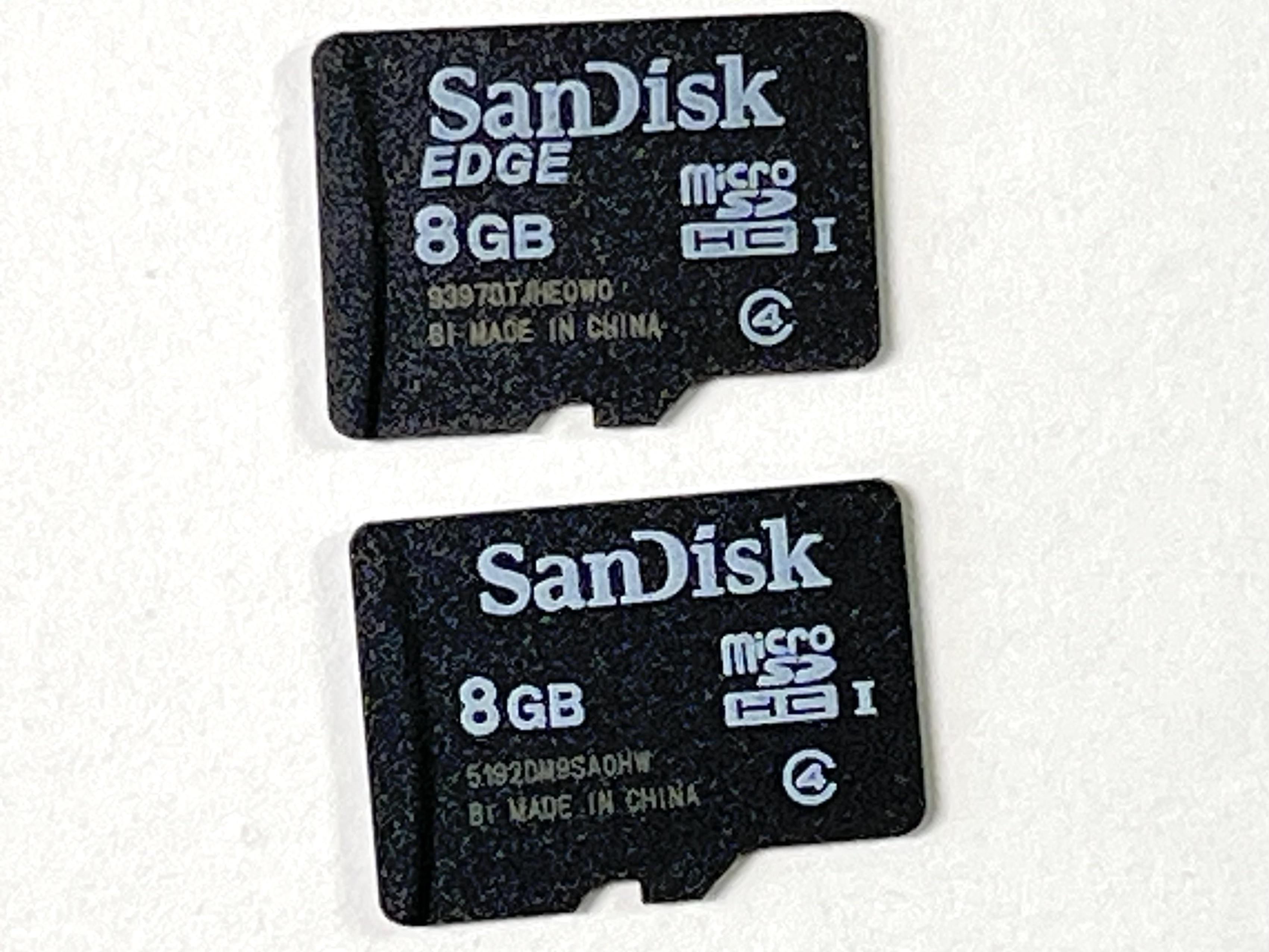
- Micro-SD cards (2)(~$4.00 each)
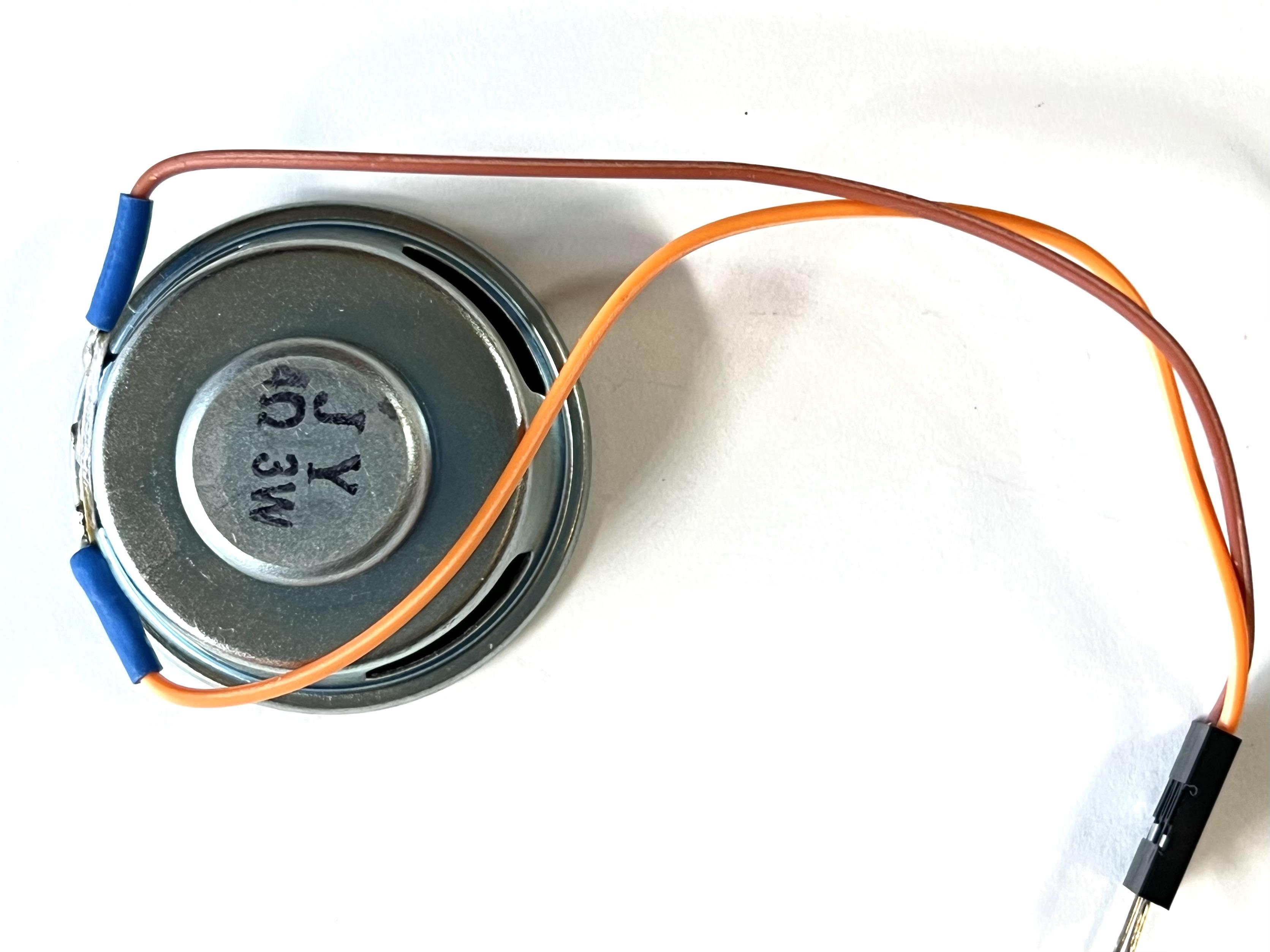
- 40-mm 4-ohm 3W speaker (~$5.00 each)
- Mini PCB (~$1.25 each)
- 2.54mm Male and Female Pin Header Connectors
- Assorted Breadboard jumper wires
- 4-pin female 1.25-mm JST connectors with 4 wires attached to single female Dupont pin connectors (2)
- 5V power adapter with connector for CYD
- 4/40 x 1/4" machine screws (4)
- M2 x 8-mm machine screws and nuts (4)
- M2.5 x 16-mm machine screws and nuts (4)
- Wire, solder, heat shrink, BluTack
- PLA filament for 3D printer
Tools
The tools I used are listed below. Any 3D printer should work.
- wire cutter
- wire stripper
- needle nose pliers
- screwdriver
- soldering iron
- 3D printer
Flash Pretrained Gesture Detection Model
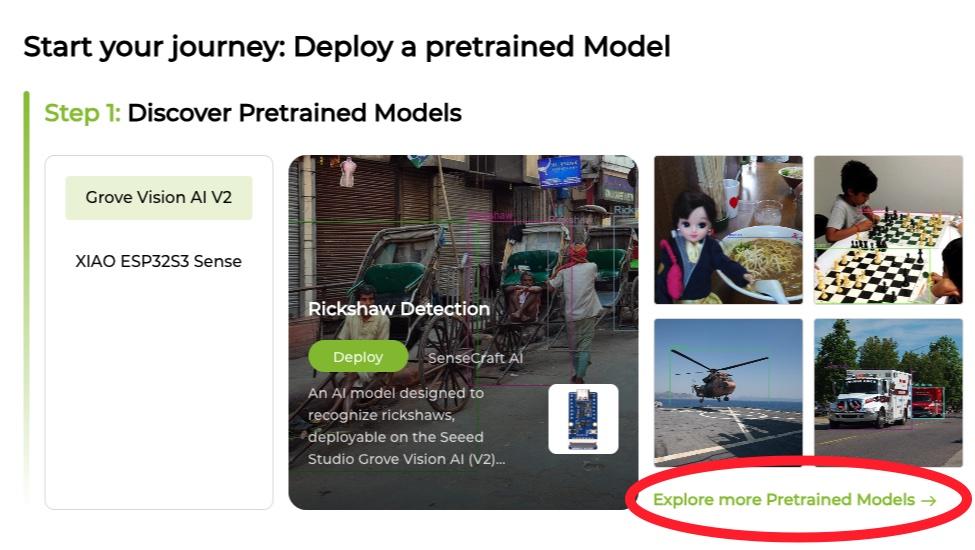
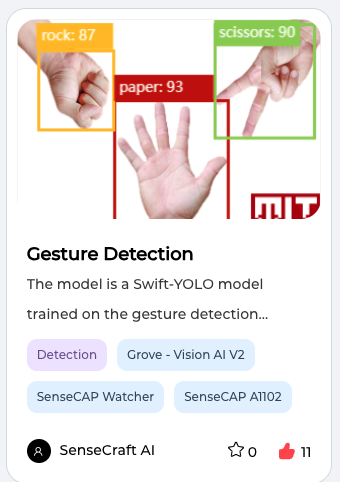
The first step is to flash a Pretrained Gesture Detection Model on the Vision AI Module V2. To do this, open the Chrome or Edge Browser on a computer and navigate to the SenseCraft AI website. Sign up for a SenseCraft account and sign in. Then, click the "Home" tab at the top of the window to see a series of steps for deploying a model. Under Step 1 ("Discover Pretrained Models"), click the option to "Explore more Pretrained Models" (see picture). A new window should open with pictures and descriptions of over 400 pretained models. Use the box in the upper left corner to Search for "Gesture Detection." Although several models will appear, only one of these will work with the Grove Vision AI V2 Module (see picture).
Clicking on the picture of that "Gesture Detection Model" will open a new window containing a more detailed description of the model. To initiate the process of flashing the model, click on the "Deploy Model" button. After making sure the camera is properly connected to the Vision AI V2 Moduie, attach the module to a computer with a USB cable and click the "Connect Device" button. Then, click the "Confirm" button when the popup window asks "Sure to deploy this model?" Another popup window will then ask for confirmation of the serial port. Select the appropriate port and click the "Connect" button. A darkened window will appear with a spinning wheel that indicates progress as the model is flashed to the Vision AI V2 Module.
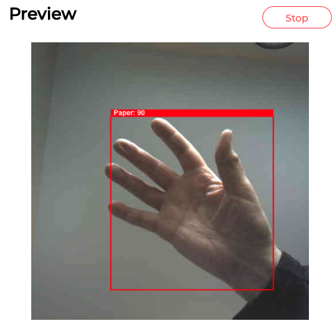
When flashing is done, the model will be running via its connection to SenseCraft. The "Preview" box mirrors what the camera sees and the "Device Logger" box shows data streaming from the Vision AI V2 Module as it continuously analyzes images from the camera. When a hand is placed in front of the camera, the model will attempt to classify the gesture as rock, paper or scissors (see picture).
After confirming that the Model is running correctly, click the "Disconnect" button (upper left) to end the module's connection to SenseCraft.
Prepare the Micro SD Cards


Consistent with with AI theme of this project, some of the tools offered by OpenAI were used to create the images of AI's hand gestures (dall-e-3 using ChatGPT) and the mp3 recordings that describe the outcome of each game round (tts-1 model). Prepare two micro SD cards by using your computer's disk utility to erase and format each card (MS-DOS-FAT32). If using a Mac computer, set the partition scheme to "Master Boot Record."
SD card for jpg files: Click the download symbol on each gesture picture (above) and save the files to your computer. The files names must be renamed after downloading (Rock.jpg; Paper.jpg; or Scissors.jpg) and saved to the SD card. Insert this card into the slot on the bottom back side of the CYD.
SD card for mp3 files: Creating this SD card is a bit more complicated because the DFPlayer Mini Arduino Library does not use the mp3 file names when executing "play" commands. Rather, it uses the ordinal position in which the file was saved to the SD card. First, download the ten mp3 files below to your computer. Next, create a new folder on the micro SD card named "mp3." Then, open the folder and copy each file into the folder, one at a time, in numerical order. Mac users may need to do one additional step to eliminate hidden files that the Mac OS inserts in the SD file directory. This step involves running the "dot_clean" command in Terminal. More information on this step is provided in the Wiki for the DFPlayer Mini. The final step is to insert the SD card containing the mp3 files into the DFPlayer Mini.
Remove CYD's LED & Solder Wires to GPIO 16 & 17
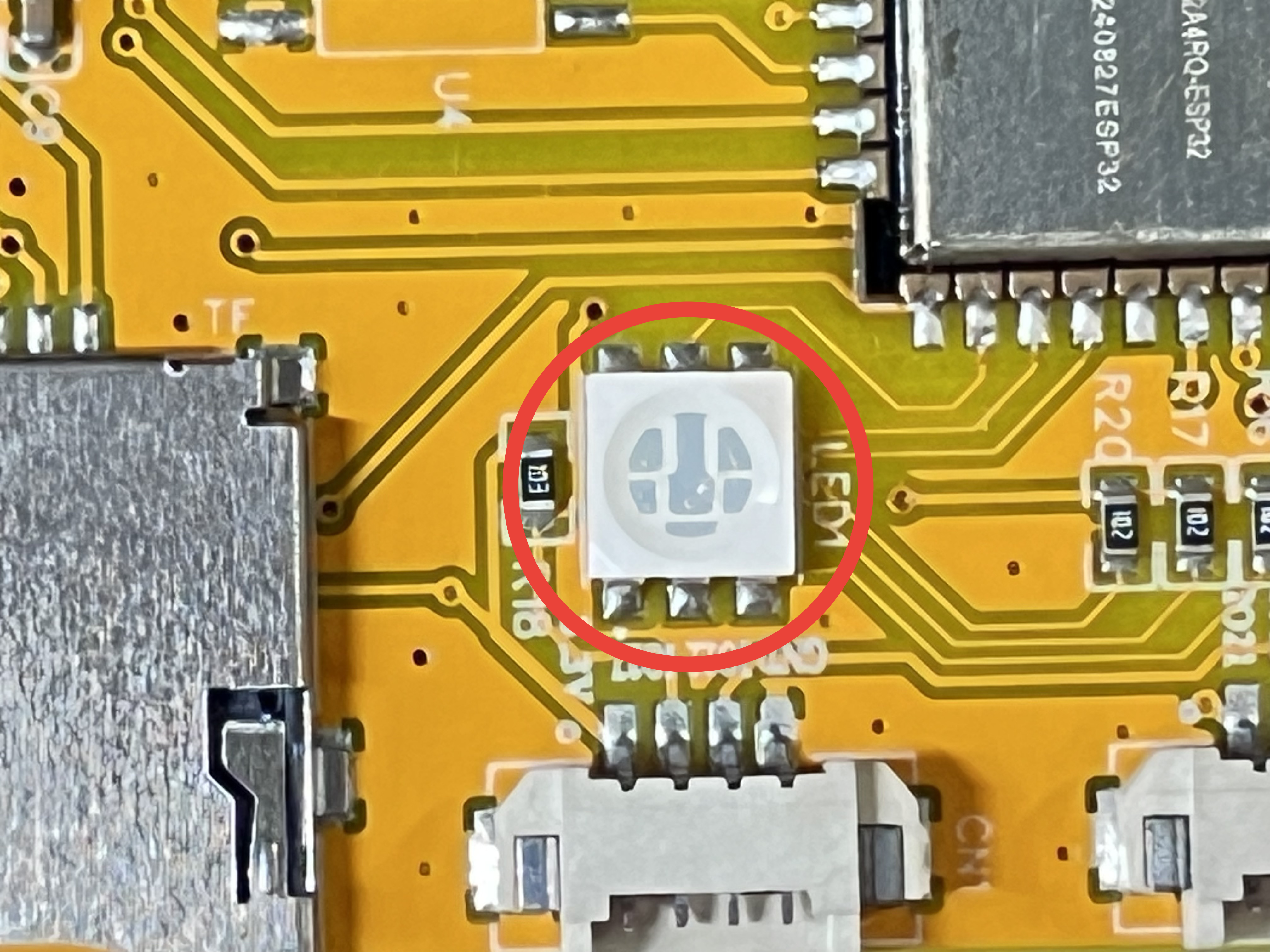
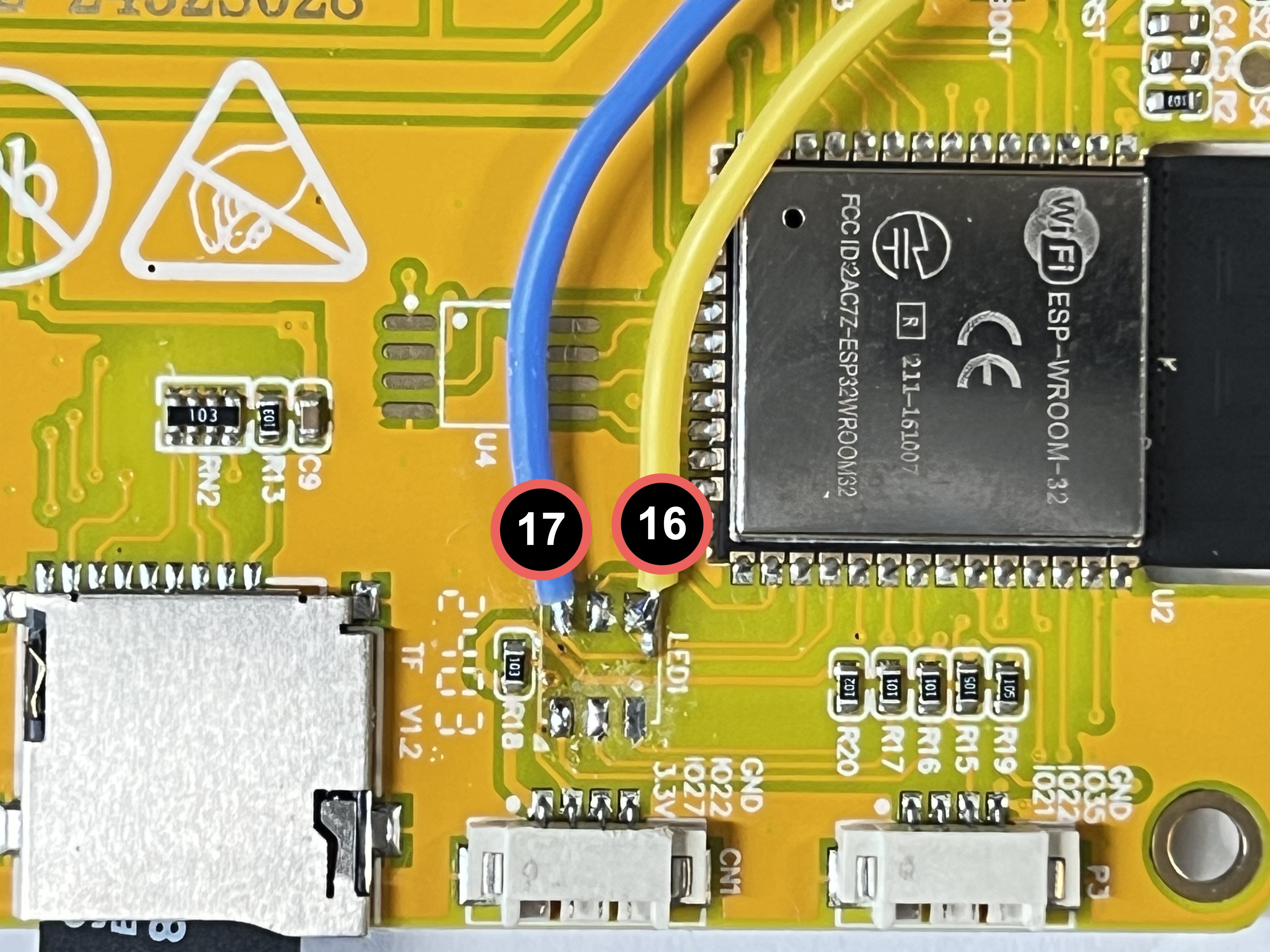
The CYD has only three GPIO pins available to connect peripherals (see this Random Nerds tutorial). Unfortunately, this project needs four GPIO pins: two for the SDA and SCL pins on the Grove Vision AI Module V2 and two for the RX and TX pins on the DFPlayer Mini. My solution to this problem was to remove the RGB LED soldered on the back of the CYD (see picture), as suggested here. This modification makes three additional GPIO pins available, including 16 and 17, which were used in this project for communicating to the DFPlayer Mini.
Removing the LED is a tricky de-soldering task because it’s surface mounted. If you're intimidated by de-soldering a surface mounted component (like I was), watch a few YouTube videos first to get tips. My best advice is to use a lot of solder flux to facilitate getting the original solder flowing and to avoid pulling the solder pads off the CYD when you remove the LED.
Solder Header Connectors to Mini PCB
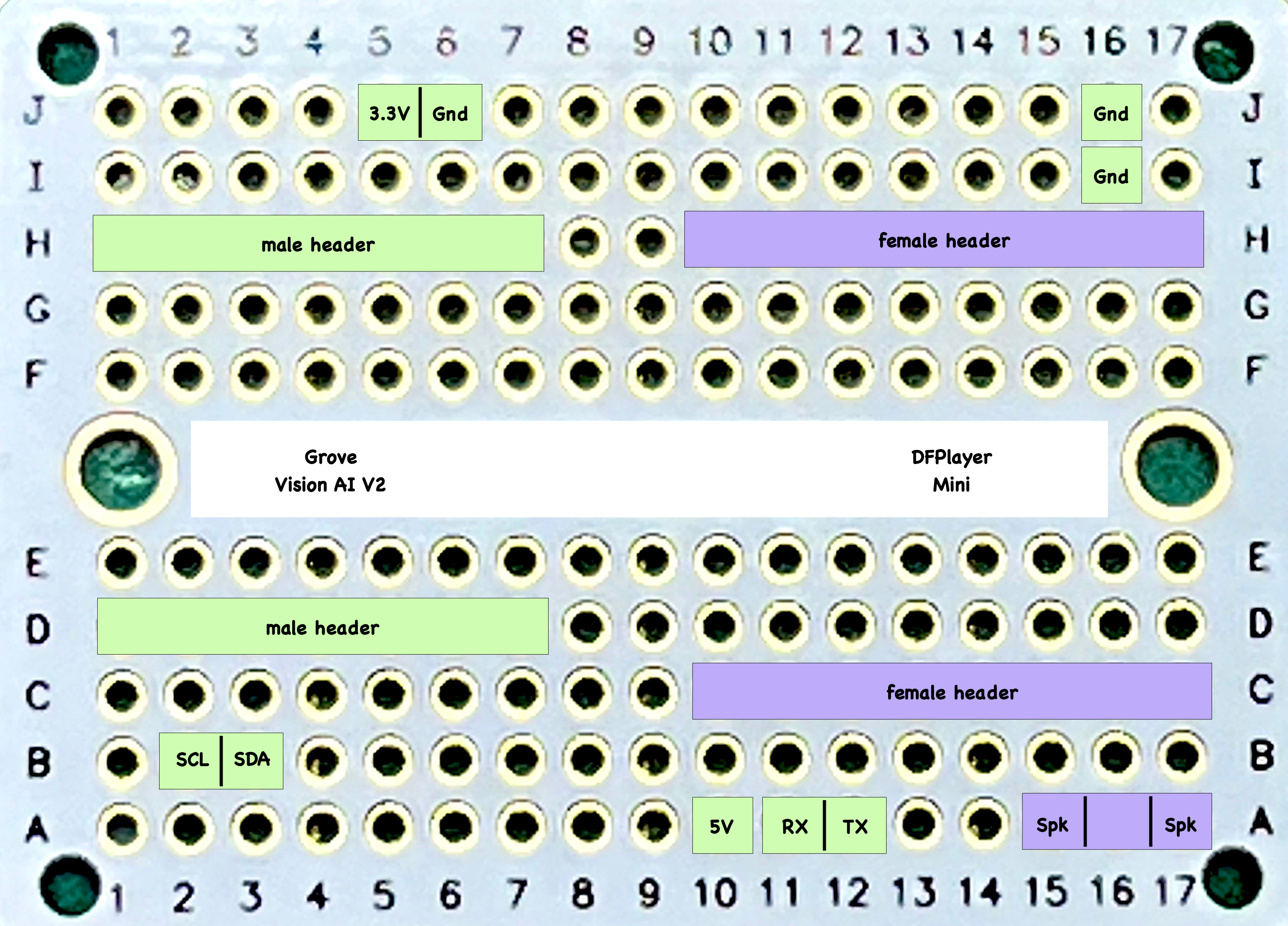
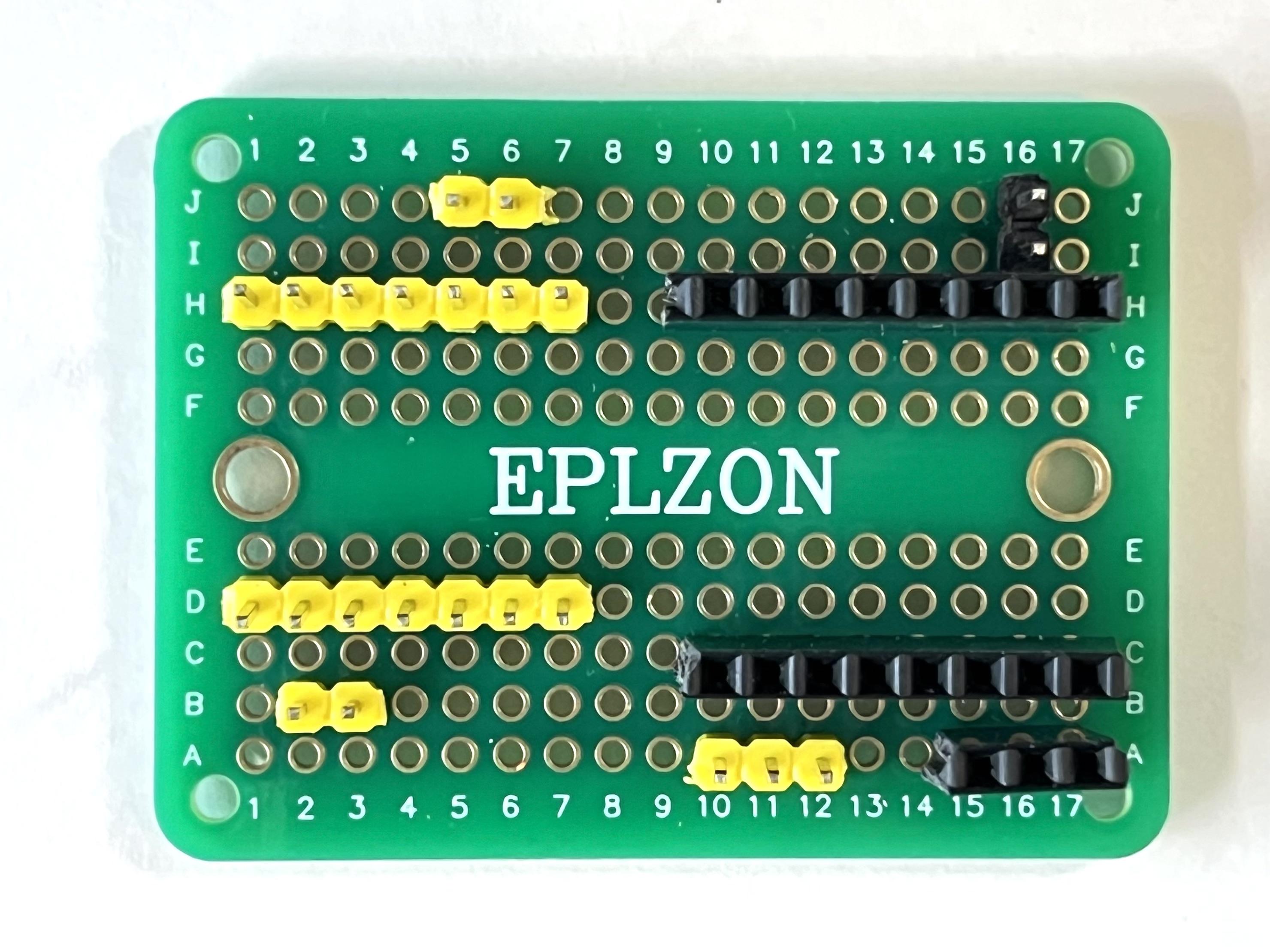
The hand-soldered PCB is basically a large connector for attaching the CYD's GPIO pins to the Vision AI V2 Module and the DFPlayer Mini. The circuit diagram shows exactly where the male and female header connectors should be soldered. The diagram's green boxes indicate the male-header locations, while the purple boxes indicate the female-header locations.
Print 3D Parts
All parts were printed without supports using PLA.
- Vision_AI_Game_Box: The main box was printed at a 0.38 layer height (20% infill).
- LID_Vision_AI_Game: The lid was printed at a 0.18 layer height (20% infill).
- Front_CYD: The front piece was printed at a 0.18 layer height (20% infill).
- backplate_Camera: This piece functions as a "spacer" to prevent the mounting hardware from contacting components or traces on the back of the camera circuitboard. It was printed at a 0.18 layer height (20% infill).
Mount Components on Game Box and Lid
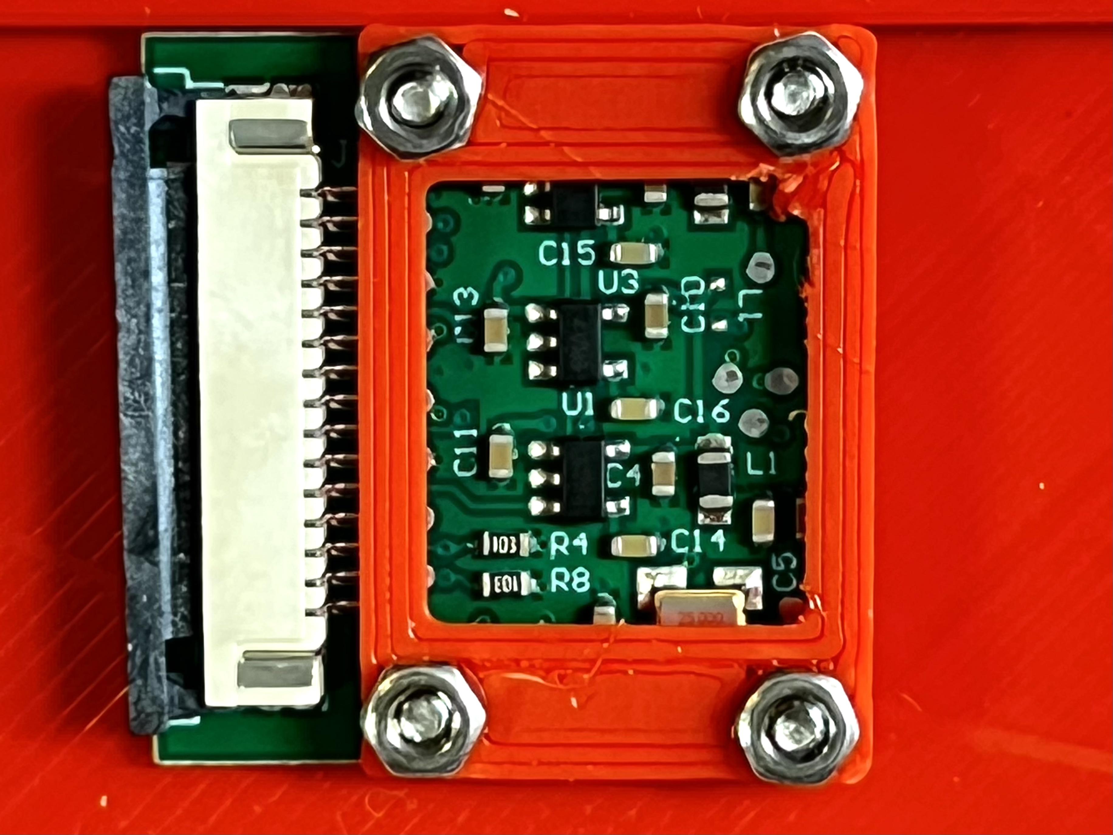
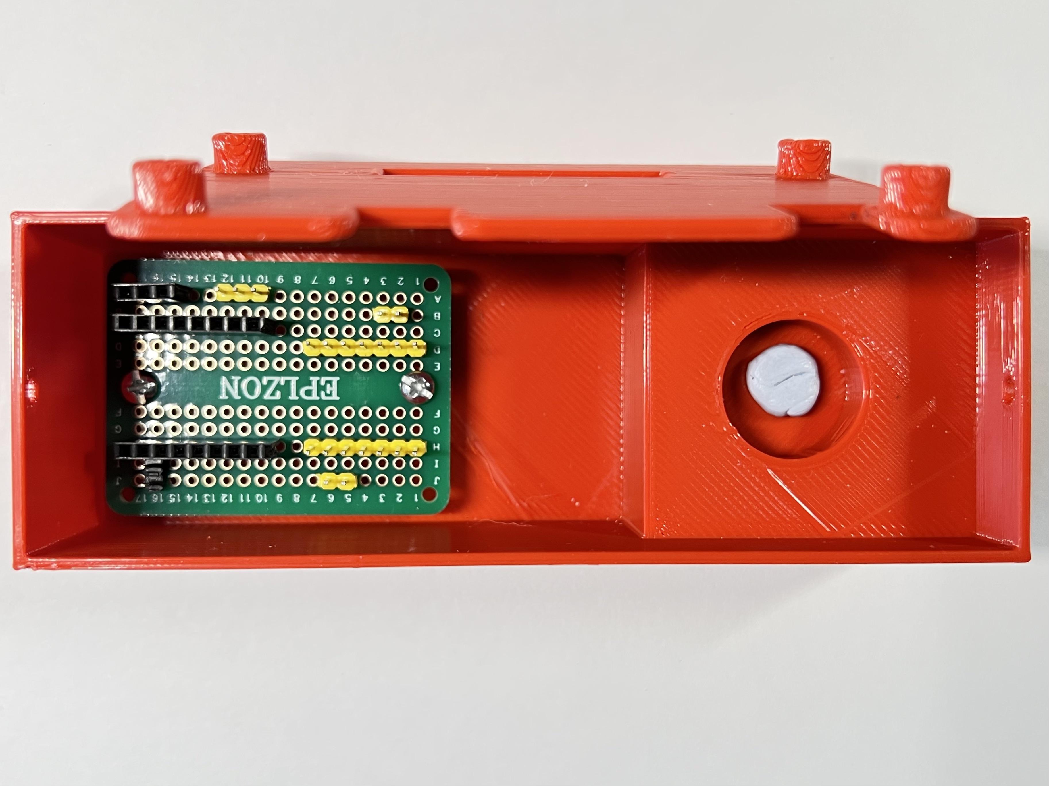
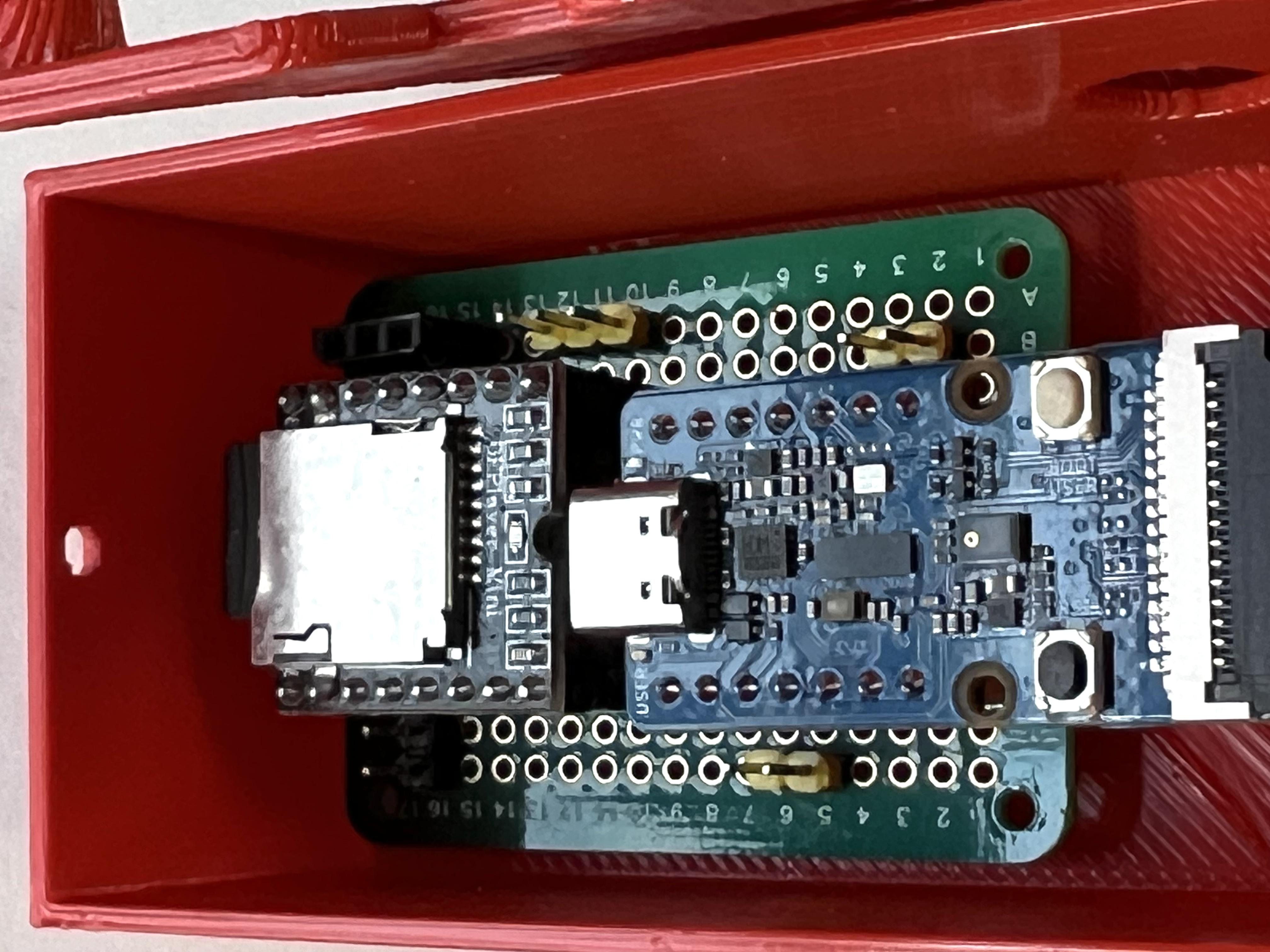
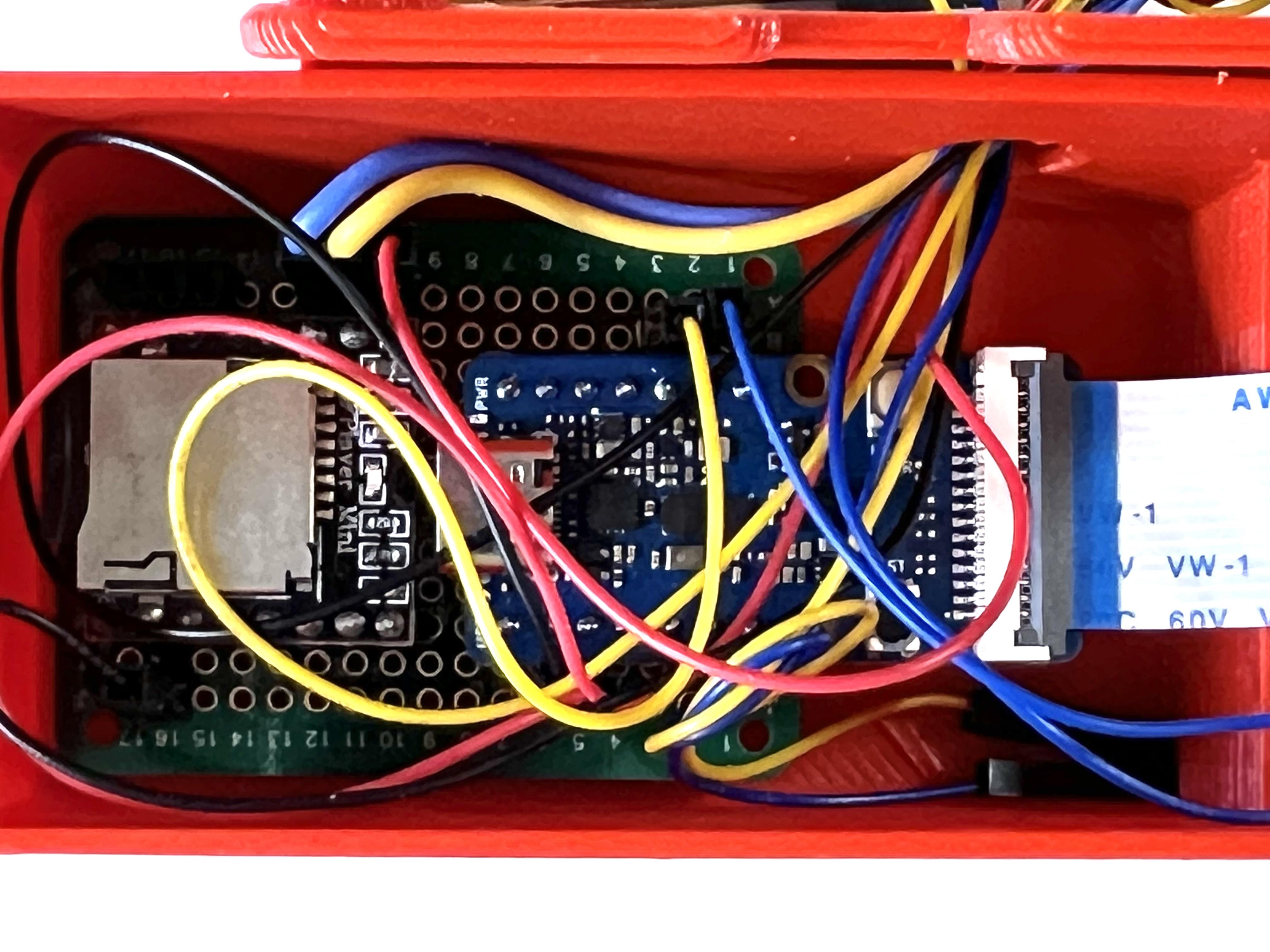
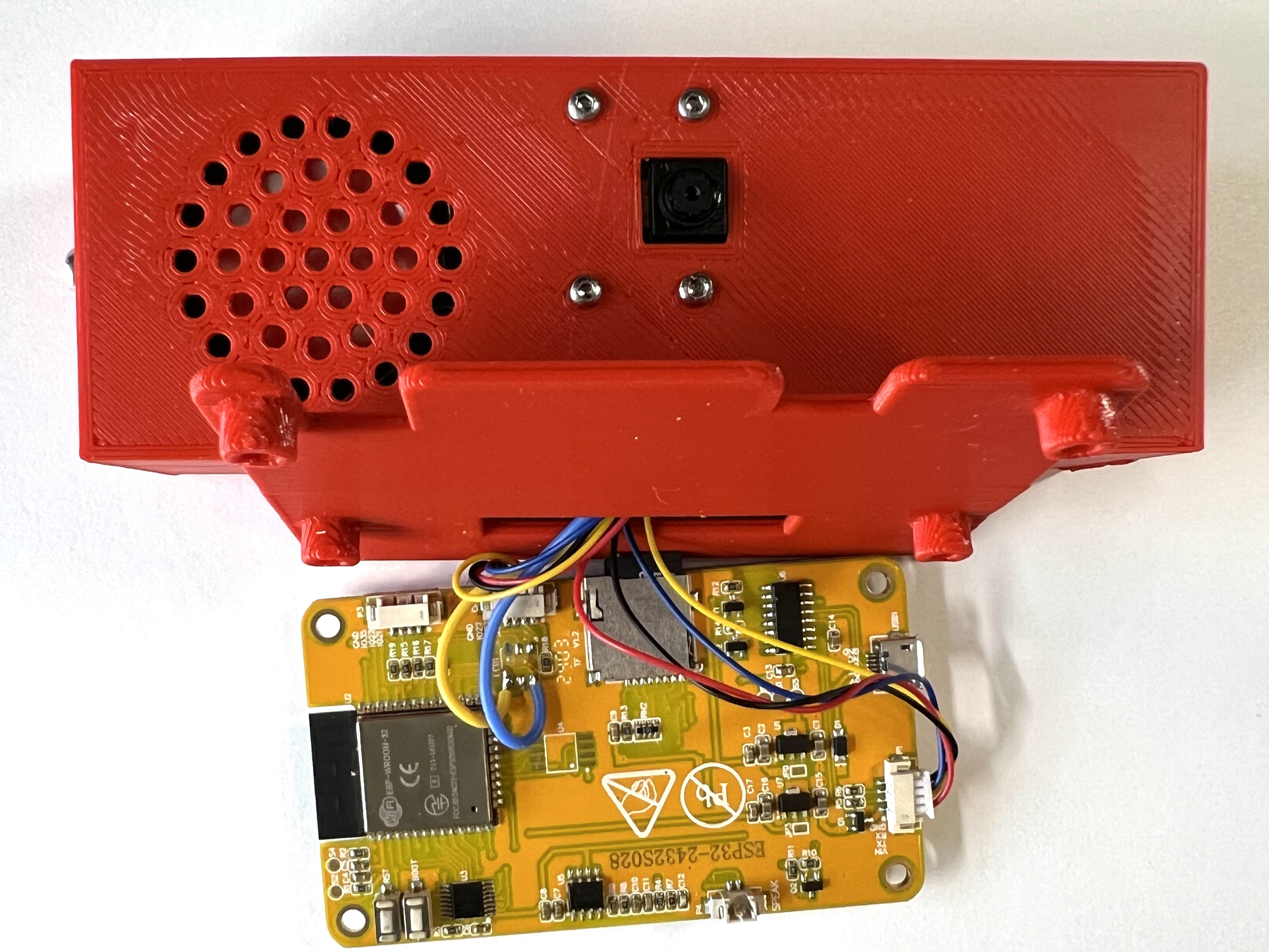
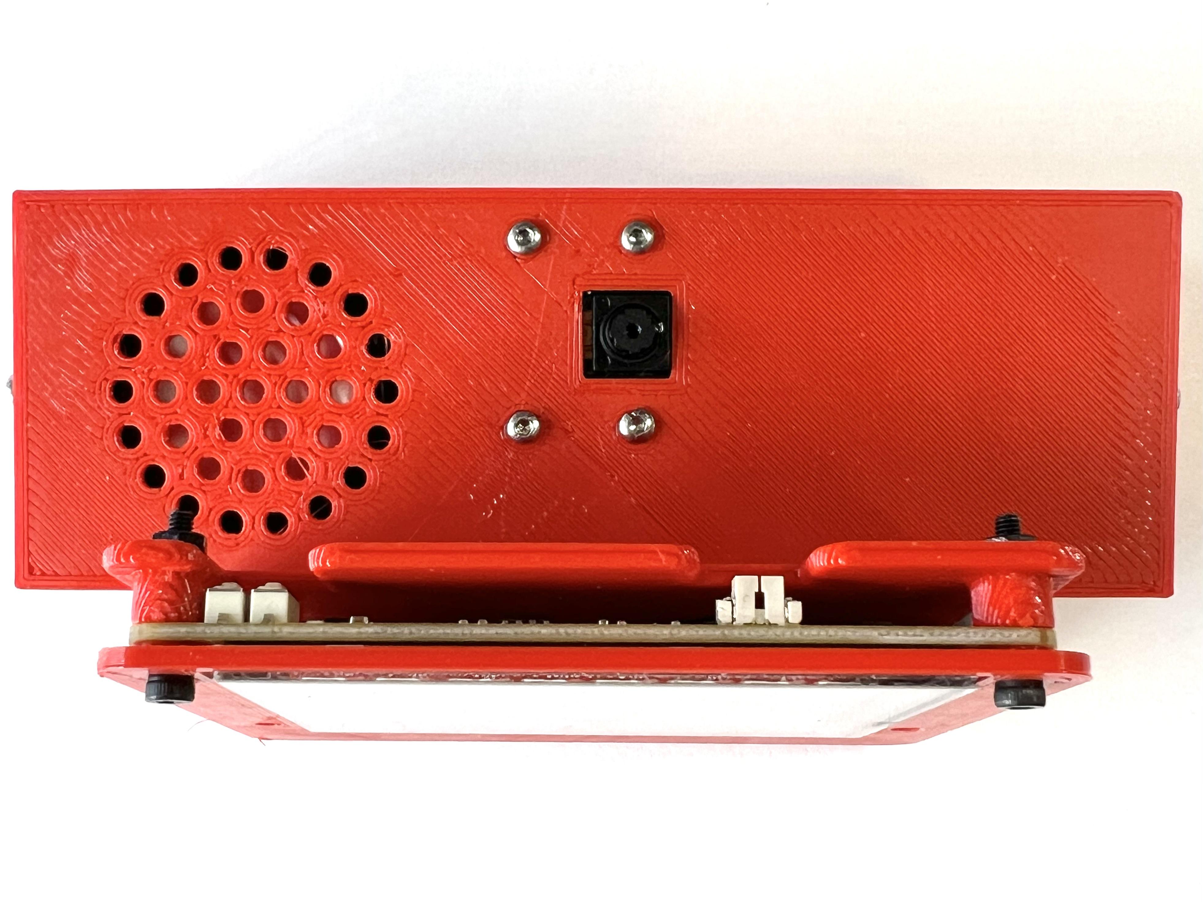
- Attach the 4-pin 1.25-mm pitch female JST connectors to the male connectors labeled CN1 and P1 (or P5 on some boards) on the CYD. Each CYD board is typically shipped with one of these connectors, with the JST connector on one end and separate female Dupont connectors on each of four colored 200-mm wires.
- Tap the holes in the mounting posts on the bottom of the box and on both ends of lid using a 4/40 tap.
- Mount the camera on the box lid using the camera backplate and four M2 x 8-mm machine screws and nuts. (see picture)
- Mount the circuitboard on the posts at the bottom of the box using two 4/40 x 1/4-inch machine screws.
- Make sure the Micro SD card containing the mp3 files is properly inserted into the DFPlayer Mini. Then, insert the DFPlayer Mini into the pair of 8-pin female headers on the circuitboard. (see picture)
- Plug the pair of 7-pin male headers on the circuitboard into the female headers on the Vision AI V2 module. (see picture)
- Insert the wires from the CN1 connector through the holes in the front of the box and attach the female pin connectors to the appropriate male header pins connected to the Grove Vision AI module: yellow wire to SDA pin, blue wire to SCL pin, red wire to 3.3V pin and black wire to Gnd pin (see circuit diagram for pin locations).
- Insert the wires soldered to pins 16 and 17 (where the LED was removed) through the holes in the front of the box. Attach the female connector on the wire from pin 16 to the male header pin connected to the RX pin on the DFPlayer Mini. Attach the female connector on the wire from Pin 17 to the male header pin connected to the TX pin on the DFPlayer Mini.
- Insert the wires from the P1 (or P5) connector through the holes in the front of the box. Attach the female Dupont connector on the red wire (labeled Vin on the CYD) to the male header pin connected to the 5V pin on the DFPlayer Mini. Attach the female Dupont connector on the black wire (Gnd) to the male header pin connected to the Gnd pin on the DFPlayer Mini.
- Solder wires with male Dupont connector pins to the two speaker terminals.
- Attach the male connector pins on the speaker wires to the female header pins connected to the speaker output pins on the DFPlayer Mini. Place the back of the speaker into the large hole inside the box. I put a small piece of BluTack in the hole to hold the speaker in place, but a small dollop of silicone adhesive would also work. (see picture)
- Connect the ribbon cable from the camera to the ribbon connector on the Grove Vision AI V2 module.
- Note: The blue and yellow wires from connector P1 (P5) are not used. Those wires can either be cut off or just tucked away under the lid (there's plenty of room).
- Attach the lid to the box using two 4/40 x 1/4-inch machine screws.
- Attach the CYD to the front of the box using four M2.5 x 16-mm machine screws and nuts. The CYD should be "sandwiched" between the CYD_front_plate and the box.
Upload Program Sketch to ESP32 CYD
In addition to downloading the Arduino IDE 2.3.4 to your computer, you will need to install the files for controlling ESP32 boards using the IDE's Boards Manager and four (4) Libraries using the IDE's Library Manager (details below).
- Download/Install the Arduino IDE: Download HERE and install on your computer (Windows or Mac OS).
- Install the ESP32 Boards Manager: Open the IDE and click the Boards Manager icon (just below the folder icon in the left column). Search for and INSTALL "esp32 by Espressif Systems" (3.0.7).
- Install the Required Libraries: Open the IDE and click the Library Installer icon (just below the Boards Manager icon) to search for and install each of the libraries listed below. Type the Library name into the search window and click INSTALL when you find the correct Library.
- Seeed_Arduino_SSCMA (1.0.1)
- TFT_eSPI (2.5.43)
- TJpg_Decoder (1.1.0)
- DFRobotDFPlayerMini (1.0.6)
- Download/Open the RockPaperScissors_CYD sketch: Download the sketch to your computer and open it by double-clicking on the sketch file (.ino suffix) icon. You may need to add the suffix to this filename after downloading. The first time you try to open the .ino file, the IDE will ask if you wish to put this sketch in a folder, which you should do (i.e., click OK).
- Download the Free_Fonts.h file: Download this file and drag it into the sketch folder.
- Prepare User_Setup.h Config File for TFT_eSPI Library: A CYD-specific configuration file is needed to use the display screen library. Instructions for downloading this file and storing it in the correct location on your computer are provided in this Random Nerds Tutorial.
- Connect the ESP32-2432S028R board to your computer with USB cable.
- Select Board and Port: Click the downward caret to open the dropdown menu on the IDE menu bar, then click "Select other board and port...". Select "ESP32 Dev Module" and the appropriate USB port in the popup menu. Click OK when finished.
- Verify the sketch to check for errors: Click the "Verify" icon in the IDE menu bar. The IDE will then attempt to compile the sketch, which should result in no error messages. Correct any errors before continuing.
- Upload sketch from computer to the ESP32 CYD: Click on the "Upload" icon in the IDE menu bar. The IDE will compile the sketch again and upload the compiled code to the CYD.
The game's "Title Screen" will appear on the the CYD after the sketch has successfully uploaded. You should also hear an audio message about the use of AI voices.
Troubleshooting: If the colors on the display do not look right (inverted), open the "User_Setup.h" config file in a text editor and search for the phrase "TFT_INVERSION." You should find two "#define" statements, one or both of which may be commented. If both lines are commented (as indicated by double slashes), try "uncommenting" one of the lines by deleting the double slashes and upload the sketch again. if the inversion persists, re-comment the first line, un-comment the second line and upload again. One of these options should correct the inversion.
The Game
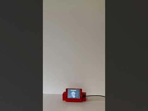
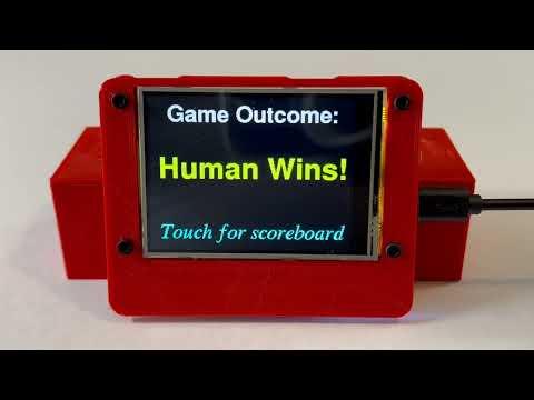
This video shows the sequence of game play as seen on the display screen. Touching the Title Screen starts the game with a display that says "Human, please show your hand!" The human's task is to make the Rock, Paper or Scissors hand gesture about a foot or more above the camera. The human's choice is shown on the next display, followed immediately by a picture of AI's choice. The game's outcome is shown on the next display, accompanied by an audio message. Touching the screen then advances to a scoreboard for the ongoing series of games. Touching the scoreboard screen starts the next round of the game. A delay of 60 sec at any point in this sequence results in the CYD going into deep sleep. Pressing the Reset button on the back of the CYD will bring back the Title Screen, starting a new series of games.
The decision to face the camera up toward the ceiling was based on observing how the Gesture Model behaved while watching the "Preview" window in Step 2 (above). I discovered that there was less interference from other objects in the camera's field of view when it was facing up than when it faced me (Vision AI thinks my head looks like a rock). That solution will probably work with most ceilings (except maybe the Sistine Chapel). I also discovered that detection occurred more quickly and accurately when my hand was at least a foot or so above the camera. At shorter distances, there was a greater tendency for every gesture to be detected as a rock.
Based on some trial-and-error testing, the sketch selects the first gesture that is detected five times with greater than 60% confidence as the human's choice. As noted earlier, AI's choice is completely random and independent of the human's. According to the Espressif System API for the ESP32's hardware random number generator, true random numbers are produced when Wi-Fi is enabled. For that reason, the Setup function puts the ESP32 WiFi in APSTA mode even though the sketch makes no other use of WiFi.
After several failed attempts to communicate with the CYD's display screen, touchscreen and SD card reader using SPI, I discovered that only two hardware SPI buses were available. That problem was solved by using the XPT2046 touchscreen's interrupt pin to detect touches since it made no difference where the screen was touched.
I've tried to insert enough explanatory comments into the code to explain what's going on, but please let me know if you have any questions.
Closing Thoughts
One limitation of the current design is that the device is not battery operated. However, it can be made portable by plugging into a small 5V power bank like this.
Those who want to keep track of their successes (or failures) playing the game can take advantage of the ESP32's WiFi capability and expand the code to upload the scoreboard results to an online database,
Perhaps the most interesting way to extend the coding would be to change the way AI picks a gesture based on the result of the last round. For example, if AI lost the first round after randomly picking "rock," it could limit its next pick to a random choice between "paper" and "scissors" (I,e., win-shift strategy). On the other hand, if AI won the first round after randomly picking "rock", it might automatically make its next pick "rock" (i.e., win-stay strategy). Game Theorists and Researchers have invested a lot of time and energy into studying this deceptively simple child's game and a few minutes of Googling will likely reveal several different strategies that might be incorporated into your code.
Having now played a few hundred games against “AI,” I’ll confess that, at times, it seems like AI is using some kind of strategy to defeat me, even though I know the code is generating a completely random gesture for AI. Game Theorists say that the optimal strategy in RPS is to play purely randomly, but that is apparently difficult for most of us humans. However, AI can behave randomly, and will completely ignore any strategies used by us humans. Go ahead, try to beat AI!
Let the Games begin!