Video Beats: Music Visualizer
by Gadget Gangster in Circuits > Audio
10484 Views, 35 Favorites, 0 Comments
Video Beats: Music Visualizer
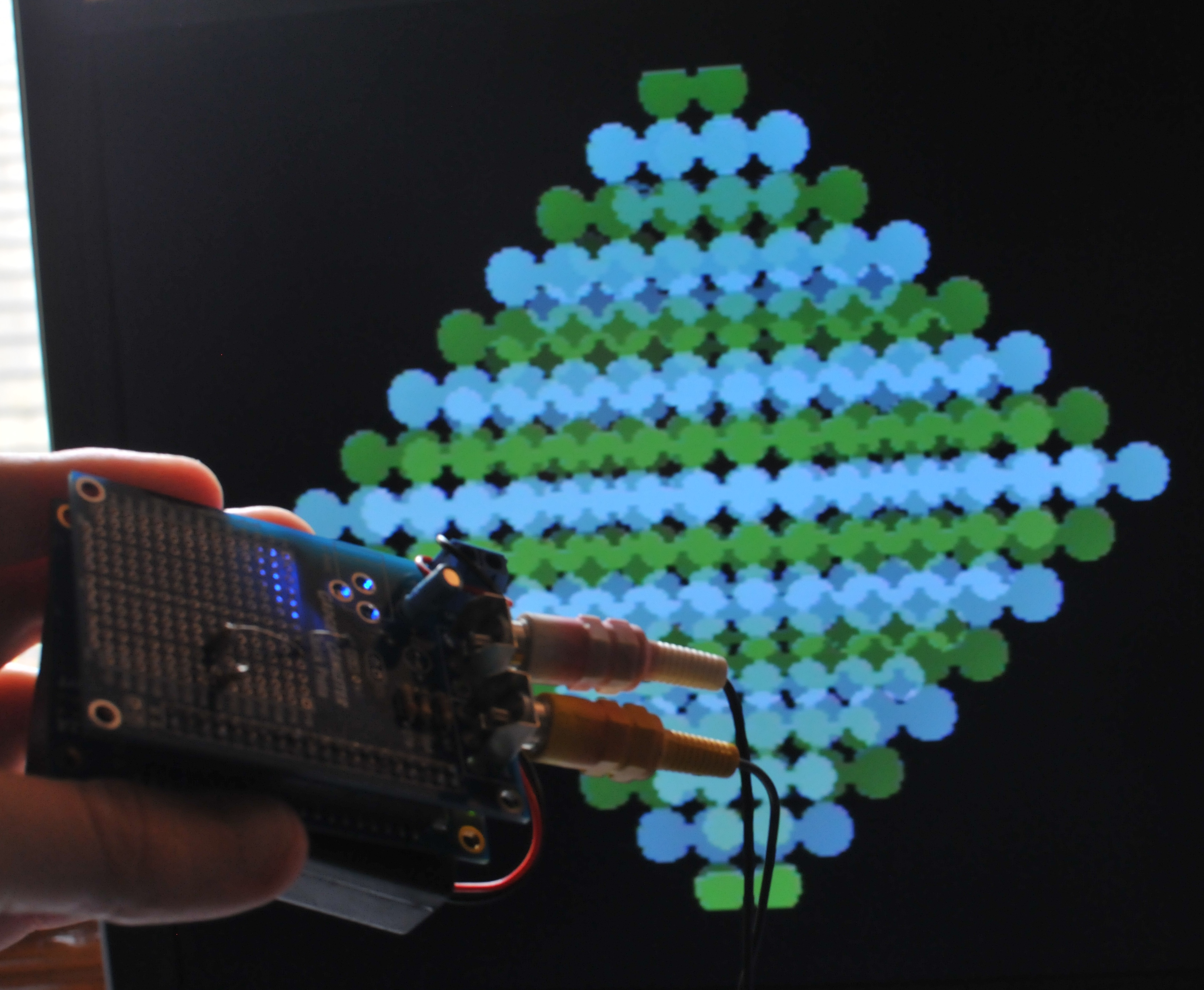
Video Beats is a hardware based music visualizer - it generates a visualization based on the music you feed it and displays it on any standard TV set. Here's a little demo (skip to 27 seconds to see the visualization);
The principle of using an analog signal to change a video display can be used for all kinds of projects, too - I'll give you some ideas on how to customize it in this instructable.
I built Video Beats because I saw a similar project in Make Magazine and thought I could improve on the concept. It was also a fun exercise in converting analog signals into digital values. Continue to the next step and I'll answer a few questions, then I'll show you how to make your own!
The principle of using an analog signal to change a video display can be used for all kinds of projects, too - I'll give you some ideas on how to customize it in this instructable.
What You'll Need;
- Your favorite Propeller board or breadboard (I'm using Quickstart w/Quick Proto).
- Two 100k resistors (Available at Radio Shack, Fry's, or online).
- A copy of the Propeller Tool, and
- The sourcecode.
I built Video Beats because I saw a similar project in Make Magazine and thought I could improve on the concept. It was also a fun exercise in converting analog signals into digital values. Continue to the next step and I'll answer a few questions, then I'll show you how to make your own!
FAQ
How's it Work?
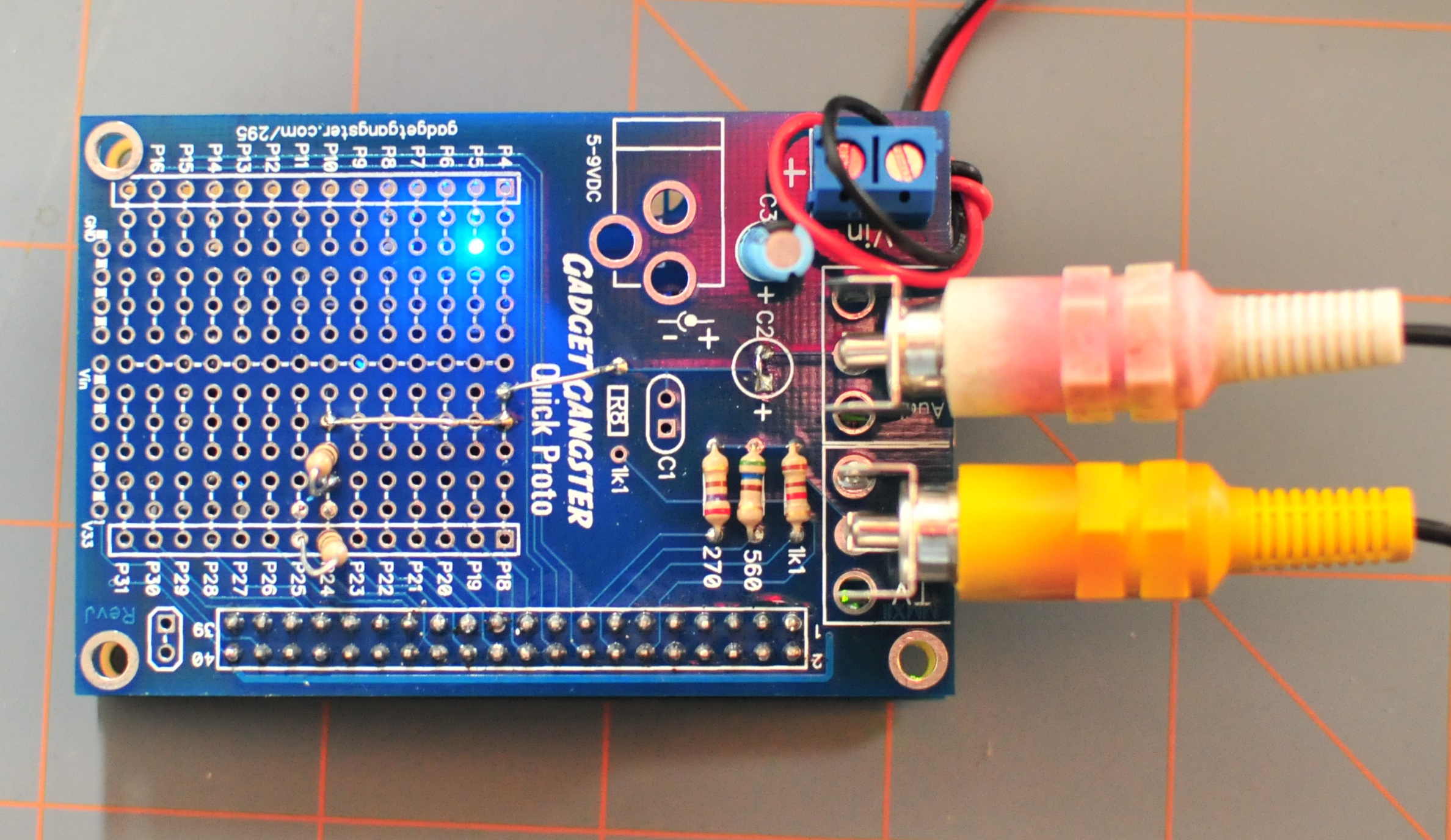
Video Beats uses a Propeller QuickStart board and a Quick Proto to sample line-level audio (like from your MP3 player) and generate video graphics. As the audio input changes, new graphics are generated to match the audio. Video is output in composite, a.k.a., the yellow RCA jack.
Seven visualizations are built-in, they will change automatically, or you can switch them manually by using the buttons on the QuickStart. You can also customize the visualizations to change colors or shapes.
How long do the batteries last?
A really long time, I'd estimate about 30 hours on 3x AA batteries. You could also power it with a USB cell phone charger or a regular Wall-wart style power adapter.
Looks great, can I use it to do <<Something_else>>?
Of course! Everything is open source, you can download the sourcecode and modify to your heart's content, I'll give you some ideas on customizing and re-using the code in this instructable, too.
Make It: Assembly
To make Video Beats, here's your shopping list;

Here's a video walkthrough of the assembly;
- 1x QuickStart and 1x Quick Proto
- 2x 100k ohm resistors (source)

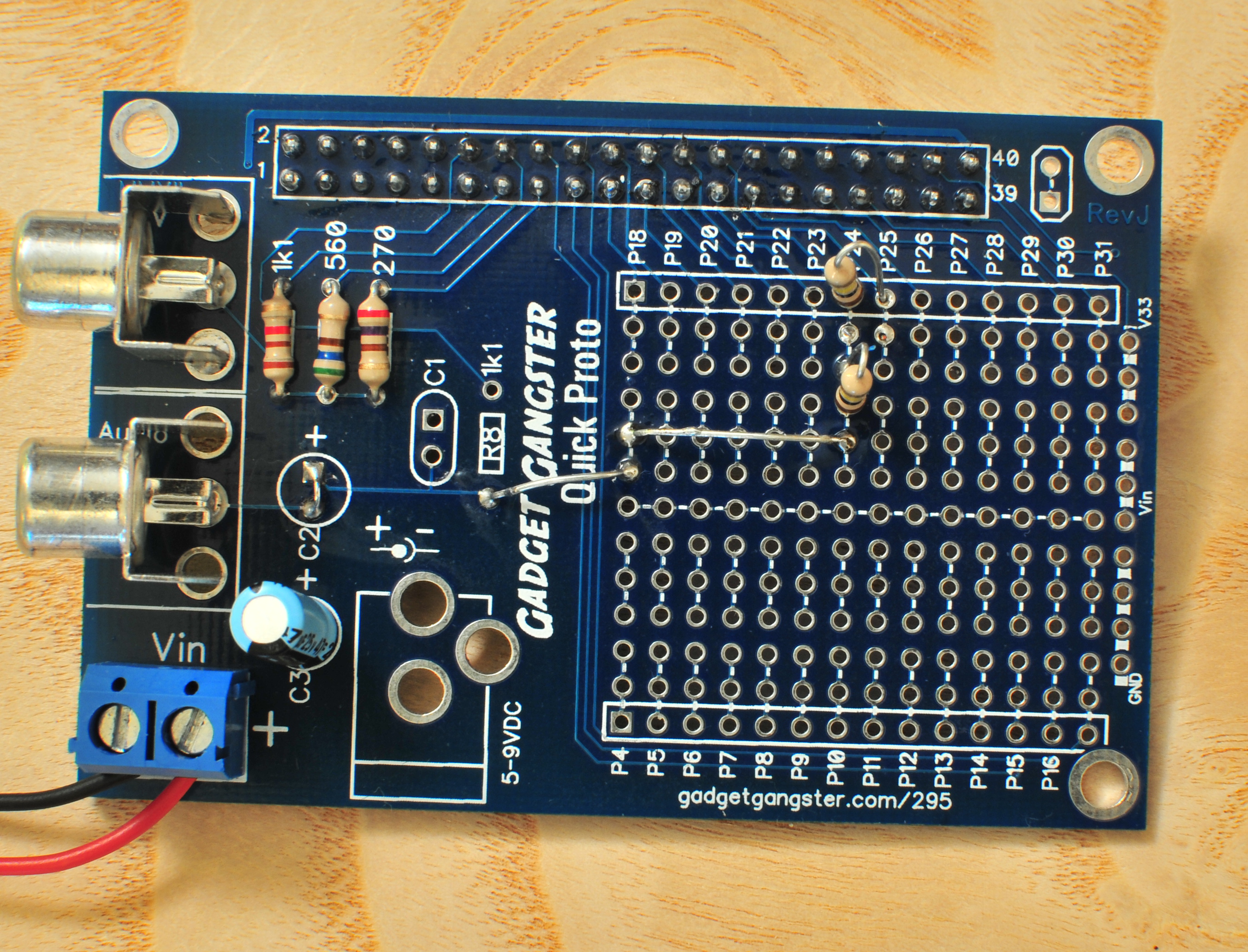
- Bridge C2 - this will allow us to use the Audio RCA jack as an input.
- Jumper R8, as shown in the photo, to go to a 100k resistor. The other end of that resistor will go to P24.
- Connect P24 to P25 through the second 100k resistor.
Here's a video walkthrough of the assembly;
Understanding the Circuit
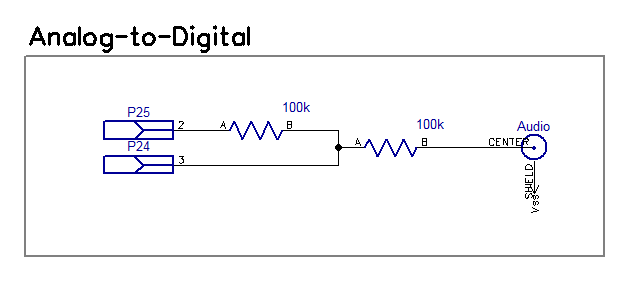
There are two parts to the circuit we've built;

We'll program one pin (D on the schematic below) on the QuickStart to do something very simple: whenever it senses Vdd, connect a second pin (/Q on the schematic) to ground. Whenever it senses ground, connect the second pin to Vdd.
What happens if we connect /Q back into D? This is what we get;

If there's no analog input connected, /Q will flip on every clock cycle (%50 duty cycle);
Most ADC's use Sigma-Delta, whether it's built into the pins, or is external, like on the QuickStart, there's an even more detailed article on Wikipedia on how sigma delta works, but hopefully my brief explanation will get your started. It takes just a little bit of code to do Sigma-Delta, and it's already in our code.

Reading the Audio Signal
The audio signal comes in analog, we use a 'Sigma Delta' circuit to convert that to digital values;
What is Sigma-Delta?
Computers live in a binary world - there are only two values, Vdd and ground. Unfortunately, signals like audio have values between Vdd and ground that we want to read. Sigma-Delta is the most common technique for reading analog values.We'll program one pin (D on the schematic below) on the QuickStart to do something very simple: whenever it senses Vdd, connect a second pin (/Q on the schematic) to ground. Whenever it senses ground, connect the second pin to Vdd.
What happens if we connect /Q back into D? This is what we get;

If there's no analog input connected, /Q will flip on every clock cycle (%50 duty cycle);
- On the first clock, D will sense ground and connect /Q to Vdd
- /Q charges the capacitor.
- Once the capacitor is charged up to Vdd, D flips /Q to ground
- Which discharges the capacitor,
- And so on.
- On the first clock, D will sense ground, connecting /Q to Vdd
- /Q charges the capacitor, but because the analog input has already brought the capacitor to .6 * Vdd, it doesn't take as long to charge it.
- Once the capacitor is charged up, D flips /Q to ground
- Discharging the capacitor
- And so on.
Most ADC's use Sigma-Delta, whether it's built into the pins, or is external, like on the QuickStart, there's an even more detailed article on Wikipedia on how sigma delta works, but hopefully my brief explanation will get your started. It takes just a little bit of code to do Sigma-Delta, and it's already in our code.
Video Output
Video output on the QuickStart takes 3 resistors, and the circuit is already built in to the Quick Proto board. Here's the circuit, it converts the digital signal the QuickStart generates into an analog signal your TV can understand.
Firmware
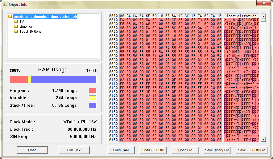
Download and install the Propeller Tool (Mac / Windows / Linux Instructions) and download the firmware (here) and unzip to a new directory on your desktop. Plug your QuickStart board into your computer and open 'pixelmusic_demoboardconverted_v5' in The Propeller Tool. Hit F8 (or Run -> Compile Current -> View Info) and info dialog will pop up. Hit the button labelled 'Load EEPROM' and your QuickStart will be loaded with the Video Beats program.
There are 4 objects in the program;
pixelmusic_demoboardconverted_v5.spin
Is the main logic of the program, it takes the analog values from the audio and uses them to determine the graphical patterns that are displayed on the TV
TV.spin
This object is the standard TV driver for the QuickStart, it generates an NTSC baseband signal. We get it to run by calling it in our main object with the line; tv.start(@tv_status)
Graphics.spin
While TV.spin creates our NTSC signal, Graphics.spin includes methods that make it easy to manipulate text and graphics on the screen. our main object uses graphics.spin by first starting it; gr.start . Then using the various methods it provides;
This object makes it easy to read the buttons on the QuickStart. We start it with buttons.start(rate), where rate is how often we want to update the button state. Every time we call buttons.state, it will return eight bits - each bit is the state one button. So, if no buttons are being pressed, Buttons.state will return %0000_0000. If button 8 is being pressed, Buttons.state will return %0000_0001, and so on.
There are 4 objects in the program;
pixelmusic_demoboardconverted_v5.spin
Is the main logic of the program, it takes the analog values from the audio and uses them to determine the graphical patterns that are displayed on the TV
TV.spin
This object is the standard TV driver for the QuickStart, it generates an NTSC baseband signal. We get it to run by calling it in our main object with the line; tv.start(@tv_status)
Graphics.spin
While TV.spin creates our NTSC signal, Graphics.spin includes methods that make it easy to manipulate text and graphics on the screen. our main object uses graphics.spin by first starting it; gr.start . Then using the various methods it provides;
- gr.clear (Clear the screen)
- gr.plot(x.y) (plot a point on the screen)
- gr.line(x.y) (draw a line from the current cursor position to the point given)
This object makes it easy to read the buttons on the QuickStart. We start it with buttons.start(rate), where rate is how often we want to update the button state. Every time we call buttons.state, it will return eight bits - each bit is the state one button. So, if no buttons are being pressed, Buttons.state will return %0000_0000. If button 8 is being pressed, Buttons.state will return %0000_0001, and so on.
Customizations
Customize your Video Beats to do whatever you want!
1 - Change the visualizations
Towards the top of the program, you'll find the color definitions;

You can change these values to change the colors that are displayed in the visualizations. You can also change the visualization patterns in the bottom of the sourcecode.
2 - Put the visualizations on something else
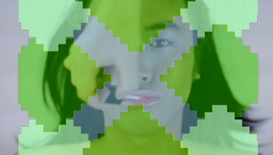
Take a look at our Touchscreen tutorial, you can easily port the visualizer to a touchscreen. Or you can take the video output and put it on a video display - the Family Sohn took an earlier version of the visualizer and put it in a music video;
Whatever you decide to use it for, have fun with your Video Beats!
1 - Change the visualizations
Towards the top of the program, you'll find the color definitions;

You can change these values to change the colors that are displayed in the visualizations. You can also change the visualization patterns in the bottom of the sourcecode.
2 - Put the visualizations on something else
Take a look at our Touchscreen tutorial, you can easily port the visualizer to a touchscreen. Or you can take the video output and put it on a video display - the Family Sohn took an earlier version of the visualizer and put it in a music video;
Whatever you decide to use it for, have fun with your Video Beats!
Next Steps
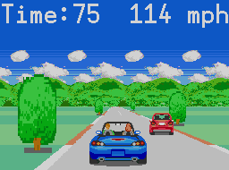
Now that you've got a running Visualizer, where do you go from here?