Vibrotactile Sensory Substitution and Augmentation Device (SSAD)
by eliett in Circuits > Assistive Tech
1183 Views, 8 Favorites, 0 Comments
Vibrotactile Sensory Substitution and Augmentation Device (SSAD)
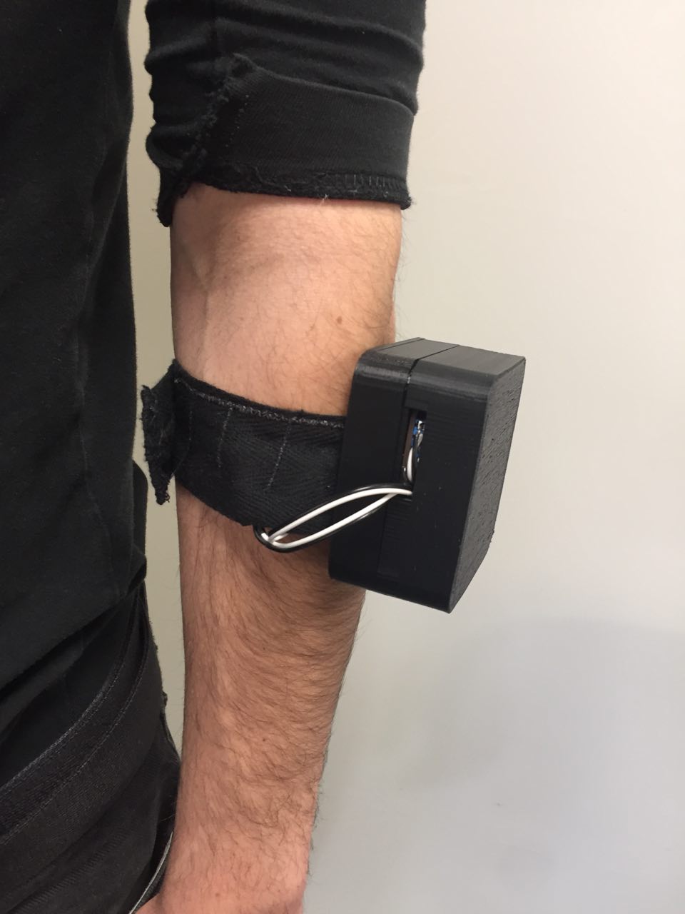
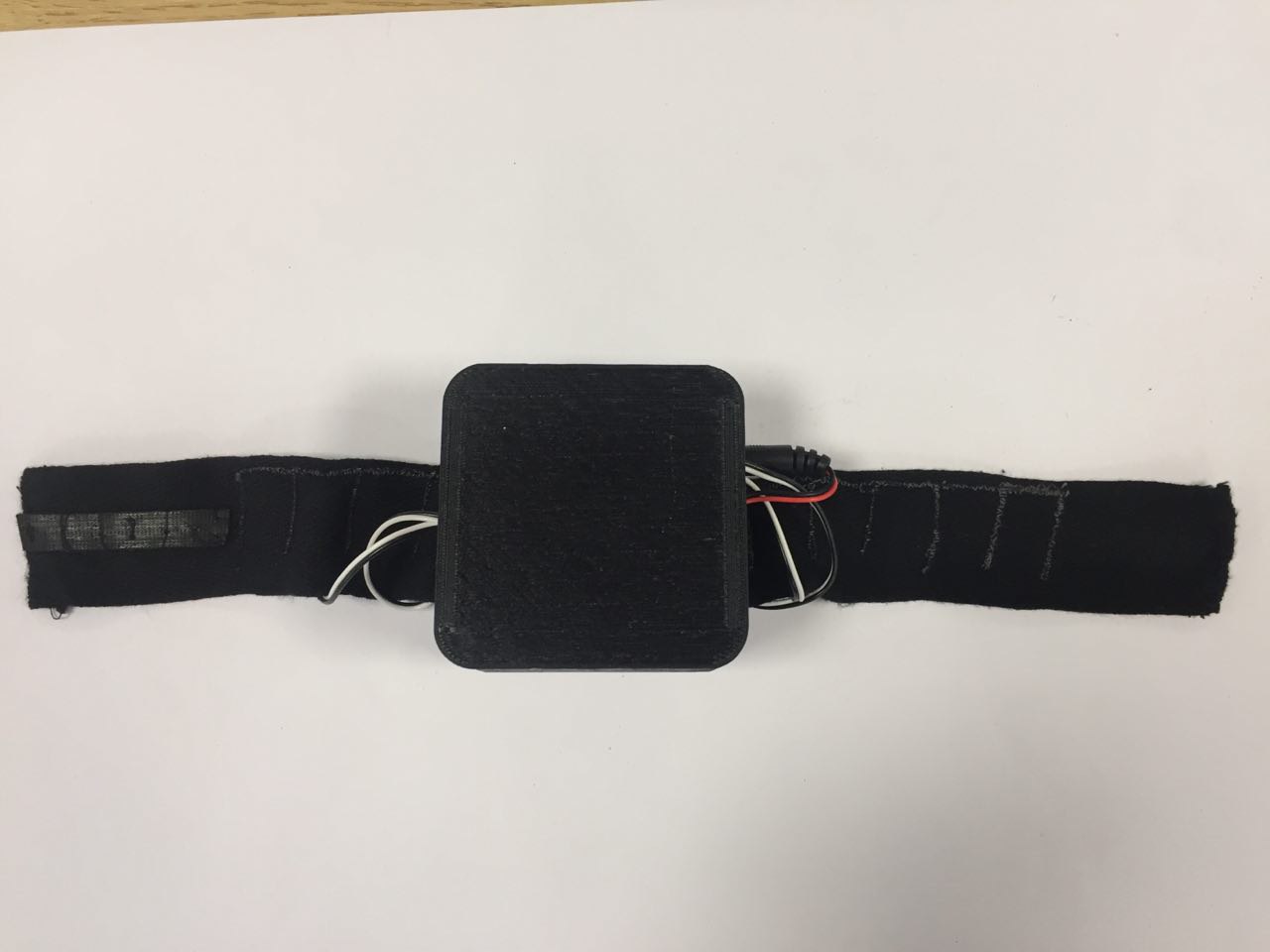
This project aims to facilitate research in the area of Sensory Substitution and Augmentation. I had the possibility to explore different ways of building vibrotactile SSAD prototypes within my MSc dissertation. As Sensory Substitution and Augmentation is a topic that concerns not only computer scientists, but also researchers from other fields, like cognitive science, a step-by-step instruction should enable non-experts in electronics and computer science to assemble this prototype for their own research purposes.
I do not intend to make advertisement for exactly one kind of brand/product. This project was not sponsored by any company. The material, I used, was chosen due to technical specifications and convenience (speed/cost of delivery, availability, etc.). For all products that are mentioned in this Instructable, equally suitable alternatives are available.
The current Instructable contains step-by-step instructions of how to build a basic SSAD prototype with up to 4 motors and analogue sensors.
Additionally to this Instructable I have created three extensions: Firstly, I published instructions about how to use more than four motors with this SSAD prototype (https://www.instructables.com/id/Using-More-Than-4...). Secondly, I created provide and example of how to make this prototype wearable (https://www.instructables.com/id/Making-the-SSAD-W...) and how to cover ERM motors without encapsulated rotating mass (https://www.instructables.com/id/Covering-Rotating...). Further, an example of how to integrate other than analogue sensors (in this case a proximity sensors) to the prototype is published as well (https://www.instructables.com/id/Including-a-Proxi...).
What is "Sensory Substitution and Augmentation"?
With Sensory Substitution the information gathered by one sensory modality (e.g. sight) can be perceived through another sense (e.g. sound). It is a promising non-invasive technique that helps people overcome sensory loss or impairment.
If the sensory stimulus, that is translated, is normally not perceivable by human beings (e.g. UV light), this approach is called Sensory Augmentation.
What skills are needed to build this prototype?
Basically, no advanced programming skills are needed to follow the instructions, provided below. However, if you are a beginner in soldering, plan some extra time to get to know this technique. In case you have never programmed before, some assistance from somebody more experienced in programming might be required.
Are there any machines or tools necessary that are expensive or not available easily?
Except a soldering iron, no machines or tools are requisite for building this prototype that you cannot easily buy online or in the next household store. This SSAD is designed to allow rapid-prototyping, which means that it should be quickly reproducible and allow an inexpensive exploration of ideas.
Supplies
Main components (about 65 £ for 4 motors, excl. soldering equipment)
- Arduino Uno ( e.g. https://store.arduino.cc/arduino-uno-rev3 , 20£ )
- Adafruit Motorshield v2.3 ( e.g. https://www.adafruit.com/product/1438, 20£)
and male stacking headers ( normally included when buying the motorshield ) - Cylindrical ERM motors ( e.g. https://www.adafruit.com/product/1438, 5,50£ / motor )
- Soldering iron and soldering wire
- Wires
Optional (see Extensions):
If ERM motor with uncovered rotating mass is bought:
- Vinyl tube
- Thin soft board
- 3D printer ( for Arduino casing)
If you want use more than 4 motors (for more than 8 same another time):
- Adafruit Motorshield v2.3 and male stacking headers
- Female stacking headers ( e.g. https://www.adafruit.com/product/85 )
- Arduino Mega for more than 6 motors ( e.g. https://www.adafruit.com/product/85 )
Soldering
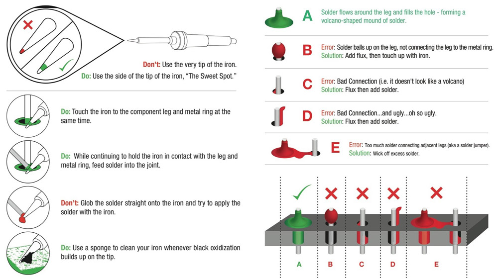
Solder the pins to the motorshield
Adafruit offers a very comprehensive tutorial of how to solder headers to a motorshield (https://learn.adafruit.com/adafruit-motor-shield-v...):
- Firstly, put the stacking headers into the pins on the Arduino Uno,
- Then, place the shield on top, so that the short side of the pins stick out.
- After that, solder all the pins to the shield and make sure that solder flows around the pin and forms a volcano-shape (see pic above, which is adopted from https://cdn.sparkfun.com/assets/c/d/a/a/9/523b1189...).
If you are a beginner in soldering, help yourself with more tutorials, such as https://learn.sparkfun.com/tutorials/how-to-solder....
Solder longer wires to the motor
As most of the motors come without or very short and thin wires, it makes sense to extend them by soldering them to longer and more robust wires. Here is how you could do that:
- Remove the plastic around the end of the wires and position them so they are in touch with each other along their exposed wires, like in in the picture.
- Solder them together by touching both wires' threads and letting the solder flow over them.
Wiring
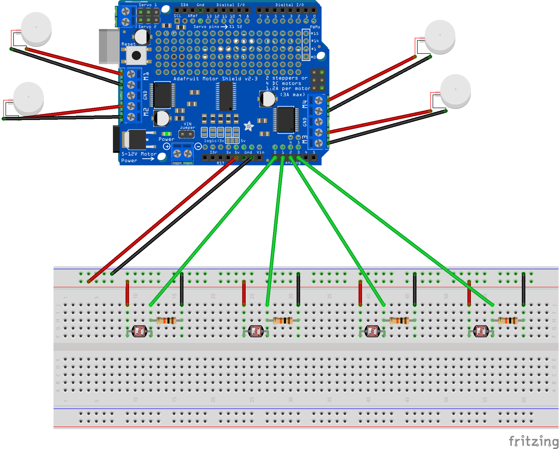
- Stack motorshield atop the Arduino.
- Screw motors into the motorshield.
- Wire analogue sensors to Arduino (in image this is done with light sensors, but same circuit looks the same for other analogue sensors).
Coding

1. Download
Download zip folder (SSAD_analogueInputs.zip), attached below. Unzip it.
Download the Arduino IDE (https://www.arduino.cc/en/main/software).
Open the Arduino file (SSAD_analogueInputs.ino) that is inside the unzipped folder with the Arduino IDE.
2. Install Libraries
For running the provided code, you need to install some libraries. So, if the Arduino file, that is attached at the end of this article, is open inside the Arduino IDE, do the following:
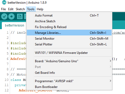
- Click: Tools → Manage Libraries...
- Look for "Adafruit Motor Shield V2 Library" in the Filter your search field
- Install it by clicking the Install Button
After downloading those libraries, now the #include statements in the provided codes should work. Check that by clicking on the "Verify" Button (Tick in the left top). You know that all the libraries work, if you the you get the message "Done compiling" at the bottom of the program. Otherwise a red bar appears and you will get a message of what went wrong.
3. Change the Code
Change the code according to your use case by following the instructions below:
Initiating Motors and their SensoryOutputs
First of all, declare which pins the motors use, as well as in what range the motors work. For example, a motor that is attached to M4 and works in a (speed) range of 25 and 175 is declared like that (beneath the MAIN comment):
Motor motor1 = Motor(4, 25, 175);
When working with small vibration motors that are driven in a range up to 3V, the motorshield has to be used with caution as it is made for running motors on 4.5VDC to 13.5VDC. To not damage the 3V motors, I programmatically restricted the Volt output of the shield to maximum of 3V (exactly 2.95V). I did that by measuring how much the maximum speed of 255 is in Volt and measured with a multimeter that this is 4.3V. Therefore, I never allowed a higher speed than 175, which is about 3V, to the motors.
Each motor will be connected with one SensoryOutput.
One SensoryOutput is composed of one or many sensory stimuli. For example, a motor could either vibrate according to one single sensor, or according to the average of multiple, differently positioned sensors.
Therefore, firstly for each motor, one SensoryOutput has to be declared. The numbers inside the brackets are the minimum and maximimum value of what the sensor (group) can perceive. For analogue sensors this is mostly 0 and 1023:
SensoryOutput output1 = SensoryOutput(0, 1023);
In the loop() function every motor is then assigned to one output value. Here you write write for each motor the following statement and instead of "output1", whatever SensoryOutput value should be connected to it. Do not forget to also change all "output1" names in this line, if you use another name for it.
motor1.drive(output1.getValue(), output1.getMin(), output1.getMax());
If you want, you can give multiple motors (e.g. motor1 and motor2) the same SensoryOutput (e.g. output1).
Further, you could give the values of multiple sensors to one motor (see next section).
Defining the Sensors
In the setup() function it has to be declared which sensors are going to be part of which motor vibration (SensoryOutput). Here is an example of how you define that the sensor that is connected to the Arduino Pin A0 should be translated into vibrations with motor1 and consequently output1:
output1.include(A0);
If multiple sensory outputs should be combined within one motor vibration, you can just add another analogue input pin to output1:
output1.include(A1);
Otherwise, just continue with the next output:
output2.include(A1);
Combining Multiple Sensors
As mentioned above, multiple sensor inputs (e.g. from A0 , A1 and A2) can be led to one motor. The code, I provide, is calculating the average of the values that are read by all included sensors. So, if this is enough for your use case and you simply want to directly map, for example, a low sensory input to a low vibration, you are done and do not have to think about the following:
If you, however, have other ideas of what you want to do with one or multiple raw sensory inputs, you can do according changes in the function int getValue() in the SensoryOutput class:
int getValue(){
     finalOutput = 0;
     // TODO do whatever you want with sensory values
     // here the average is built, if multiple values are combined
     for (int i = 0; i < curArrayLength; i++) {
         finalOutput += analogRead(valueArray[i]);
    }
    return finalOutput / curArrayLength;
  }
4. Upload the Code to your Arduino Prototype
Plug in the Arduino Prototype (from Step 2) to your PC.
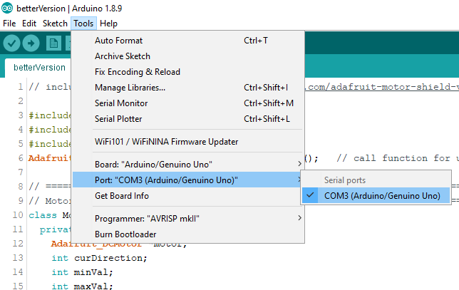
Click Tools → Port → Select the Port, where Arduino/Genuino Uno is written in brackets
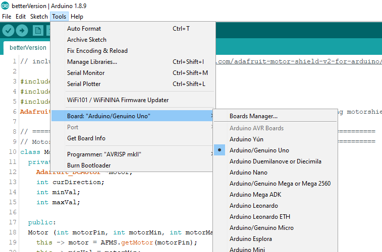
Click Tools → Board → Arduino/Genuino Uno
Now, the motors should run according to the inputs of the analogue sensors. If you want, you can disconnect the Arduino from you PC and plug it to another power source, like a 9V battery.
Downloads
Possible Extensions
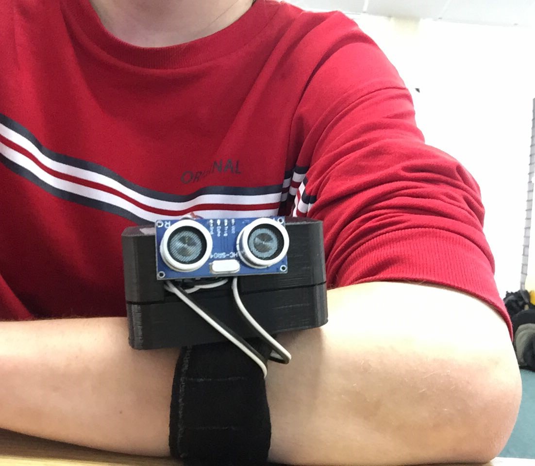
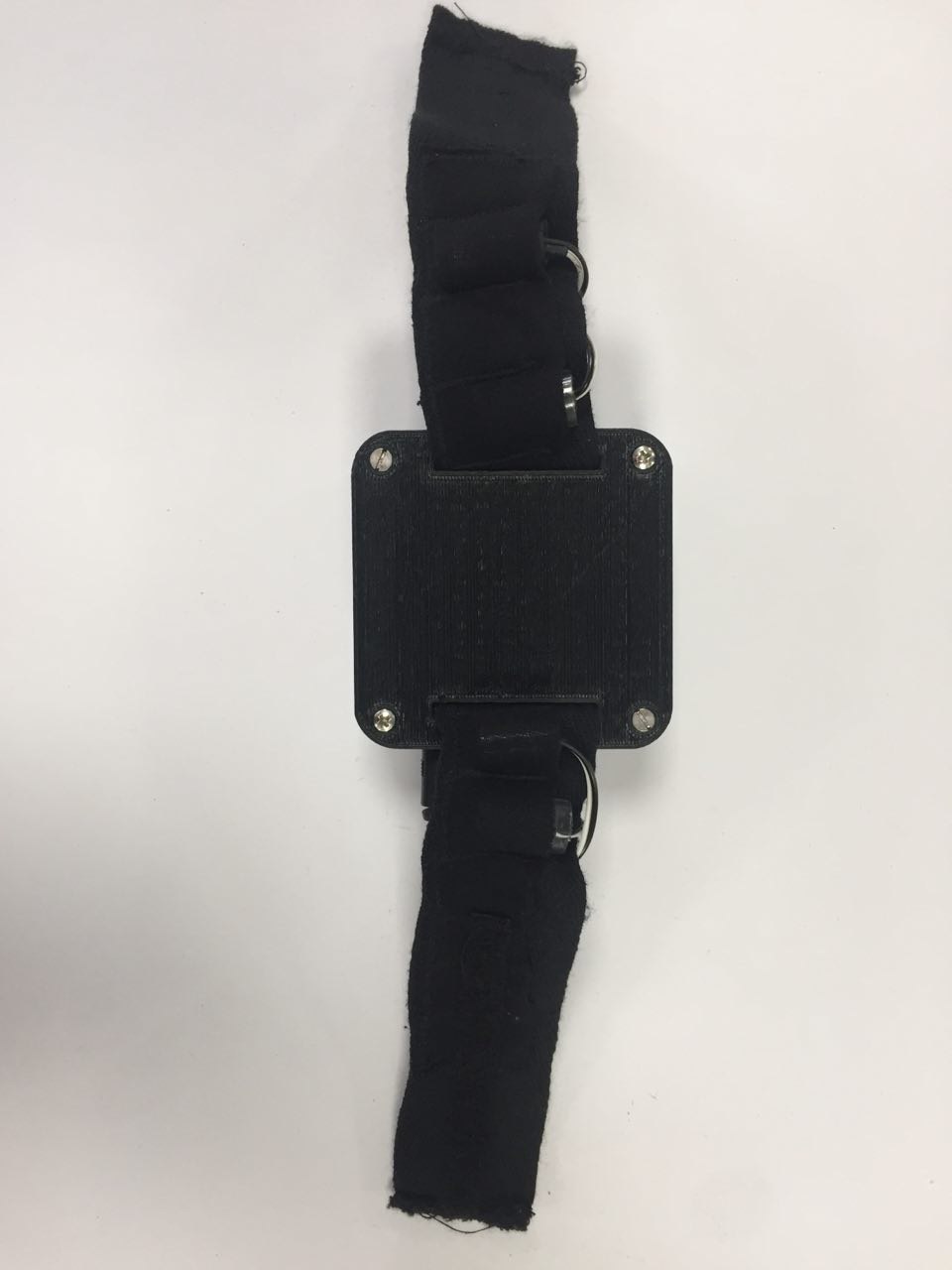
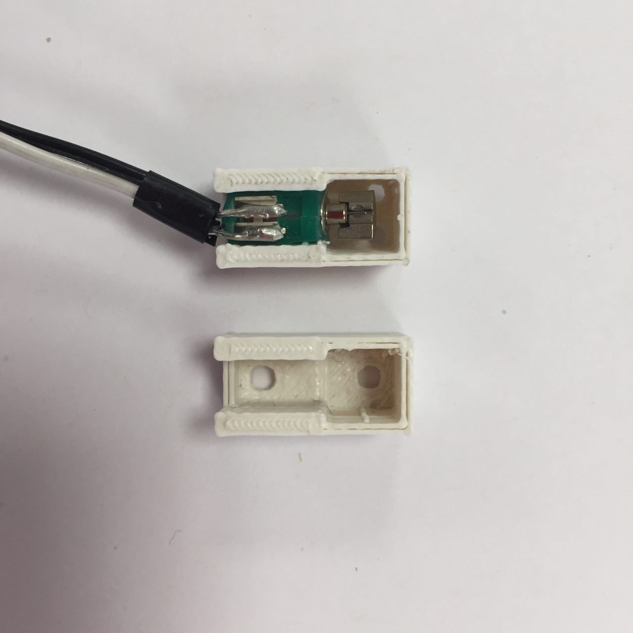
The prototype you have just built allows exclusively analogue inputs and can drive up to four motors. Furthermore, it is not wearable yet. If you want to extend those features, have a look at following instructions:
- Covering Rotating Masses of ERM Motors: https://www.instructables.com/id/Covering-Rotatin...
- Making the SSAD Wearable: https://www.instructables.com/id/Making-the-SSAD-...
- Using more than 4 Motors - Stacking multiple motorshields: https://www.instructables.com/id/Using-More-Than-...
-
Using an ultrasonic proximity sensor as SSAD input: https://www.instructables.com/id/Including-a-Proxi...