Vex CTE Robotic Arm DIY/3D Printed
by Blenderguy in Circuits > Arduino
308 Views, 3 Favorites, 0 Comments
Vex CTE Robotic Arm DIY/3D Printed

If you're a teacher/educator and want a vex CTE arm but can't get funds for one then this project will give you an affordable* version of the arm
Supplies
You'll need a
- 3D printer(black & white filament)(GO through the instructable and print all the parts.)
- wires(preferably bell wire) and breadboard connectors(female to female)
- Arduino Mega+sheild-->https://www.amazon.com
- Male tamiya plug
- vex 7.2v battery
- 3 vex servo modules(276-2162)
- 2 sg90 servo
- soldering
- 3x 6202rs bearing
- 2 lm7805
- buck boost converter
- linear potentiometer length 85mm (optional)
- i2c LCD display(16x2)
- 20 mmhttps://www.aliexpress.us
- pca9685
- glue
- 25 kg servo(180)
- cable cover
- 8/32 screws 2x(1/4) 4x(3/4)
- 3mm shaft
- extension cords
- usb B cable
Board Prep
Take the shield for the arduino and solder 3 wires together in a row witch means 3 rows of wires soldered together, one should be soldered to gnd, one to 5 volt and the 3th one will be used later make sure they are not touching each other and are spaced apart
Servo Prep
Take your 3 vex motors and cut the wires off the end, then solder the female beadboard wire on to it so it has a female end instead of the male ones with the pins then cut the standoffs off.
Board Assembly
place your shield on the mega, then place the pca9685 on the assembly and wire the 5v to 5 volt wire from step one, do the same for gnd, then wire/solder scl pin 21 and sda to pin 20 from the diagram to pin 20 (use the screw terminals on the shield) 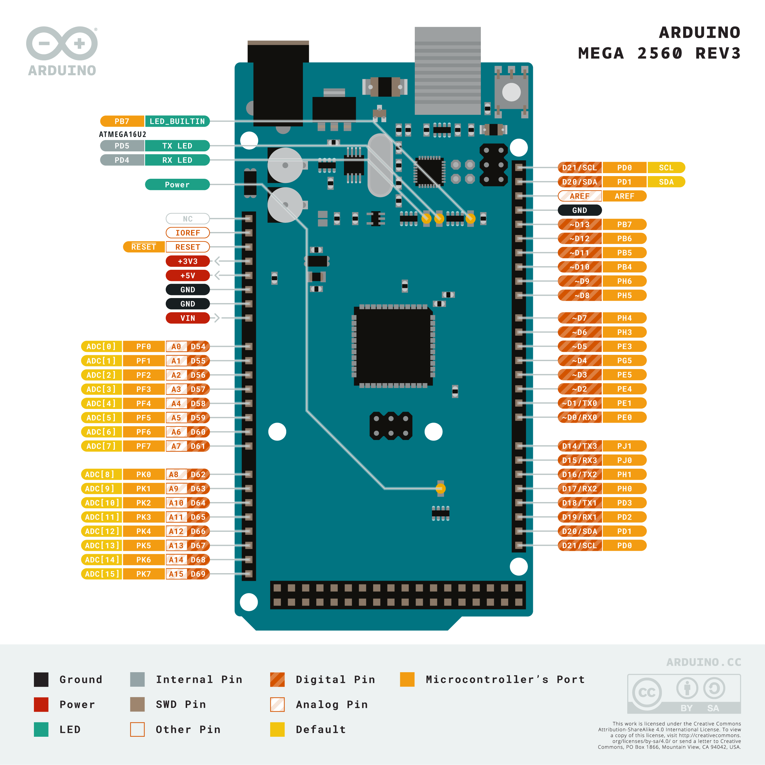
Downloads
First Layer

Now put the Assembled board into the part(think if the full board was in the picture instead of just the Arduino)
LCD

put the lcd in the (colored black)printed part attached to this step in the front, it might take a bit of heat to fit the lcd into the part so if it doesn't want to go in soften the part with a lighter, then conect 5v to 5 volt, gnd to gnd and scl to pin 21 and sda to pin 20 BUT use the pin headers instead of the screw terminals.
Downloads
Voltage for Servos and Finishing the Base


Then solder the positive of the Tamiya connector to Vin of the Arduino shield and to the in+ of the buck boost converter then connect the gnd of the Tamiya connector to the Arduino's gnd and the buck boost convert then adjust the converter to 8 volts then connect the OUT+ to the pca9685's + screw terminal. OUT- doesn't need to be connected but can be connected to the pca9685's GND screw terminal then put and glue the tamyia connector to the hole on the right in the 3d printed part with the lcd ,put the converter above the little box Infront of the Arduino you should have something like the picture above
First DOF

Take a 3mm shaft, a bearing and one of your VEX motors and print this parts and in the image, B is a bearing, M is the motor, 11 is the part named 11 and 3mm is the shaft or just use a vex shaft, make sure the shaft is 11.5 mm long
glue the part 11 to the bearing and then the bearing to part no.8 or the big part, and one you've glued it in place flip it over and attach the vex motor then glue it, make sure the shaft is linking the motor to part no.11
Second DOF

For this step, Take that 20kg motor you bough and then print this part below, one you've removed the support; set the angle to 0 then insert the motor into the part as shown in the image and route the servo wire down the hole in the servo slot then print put the servo arm on not angle so it looks like + when you look at it straight, screw it in and then screw part 14 onto it, so take a thin screw and screw 14 into the servo arm, make sure 14 prints flat
Wiring and Prep for Third DOF


cut the cable cover to 170mm in length, print the parts take the one with the square hole in it, then pull and push 3 sets of 50 or 60 cm of extension cord through that you bought then put it onto the Second DOF using the square hole, make sure it is aligned with the zero degrees and screw it in with the 3/4 screw. Make sure the part that looks like the TF2 logo is under the screw
Third DOF
Route the extensions through the 3d printed, put a vex motor into it and then take another 3mm shaft of the same length and push it into NO.18, drill a hole the size of a 8/32 screw(the screw you've bought) and put it into the servo then put the bearing onto it you can use a lighter. route a 30 mm extension to the servo and connect it to the servo
Fourth DOF
(note:21 won't print with supports)spin the second servo to point up then spin the third servo Counter clockwise until it stops then place 19 on it with the flat side facing up, place 20 onto it and screw it into place with a 3/4 screw. cut a 3 shaft to 105 mm. put a servo into part NO.20, connect the servo to one of the extensions we routed earlier. put the shaft we just cut onto it and put 21 onto it and glue it
Fifth DOF

cut one of the extension cords and strip it, do the same for the sg90 servo and solder it o the lm7805 as show put the print onto the shaft of the previous servo(sand the edges so it fits into the slot) then put the servo into the U shaped slot with the output of the servo pointing out
Downloads
END EFFCTOR

Drill the parts so they fit to assemble. just look at the picture(USE GLUE) and do it ALSO do the thing with the stripping wires and lm7805 from the last step
Downloads
(OPTIONAL) Controls


Wire the Linear potentiometers so that the Positives and GND are connected. connect the gnd to ground of the board and + to positive of the board. them connect the outputs to the arduino's analog as shown
Downloads
Attaching the Wires and Finishing Up

Use this diagram to help wire the servos to the PCA9685(USE the numbers) place the robotic arm on the base then use the 1/4th screw and screw it into one of the front holes and across it us the last 3/4 screw and now
YOU ARE FINISHED!!!!!!! :DDD
Code
Here I wrote some code, you can see it below THIS ONE IS FOR THE POTENTIOMETERS
// Potentiometer

#include <Wire.h>
#include <Adafruit_PWMServoDriver.h>
#include <LiquidCrystal_I2C.h>


#define MIN_PULSE_WIDTH       650
#define MAX_PULSE_WIDTH       2575
#define FREQUENCY             50


LiquidCrystal_I2C lcd(0x027, 16,2);
Adafruit_PWMServoDriver pwm = Adafruit_PWMServoDriver();


int Estop;
int Ebutton = 13;
int Estopper = 8;
int controlA = A8;
int controlB = A6;
int controlC = A10;
int controlD = A3;
int controlE = A4;
int controlF = A5;
int F = 3;
int B = 5;
int L = 6;
int R = 7;


int motorA = 0;
int motorB = 4;
int motorC = 8;
int motorD = 7;
int motorE = 11;
int motorF = 3;
void setup()
{
  pwm.begin();
  pwm.setPWMFreq(FREQUENCY);
  pinMode(Ebutton, INPUT);
  pinMode(Estopper, OUTPUT);
// Lcd print
lcd.init();
lcd.backlight();
lcd.setCursor(0, 0);
lcd.print("Booting");
delay(250);
lcd.clear();
lcd.setCursor(0, 0);
lcd.print("Booting.");
delay(250);
lcd.clear();lcd.setCursor(0, 0);
lcd.print("Booting..");
delay(250);
lcd.clear();lcd.setCursor(0, 0);
lcd.print("Booting...");
delay(250);
lcd.clear();lcd.print("Loading");
delay(250);
lcd.clear();lcd.setCursor(0, 0);
lcd.print("Loading.");
delay(250);
lcd.clear();lcd.setCursor(0, 0);
lcd.print("Loading..");
delay(250);
lcd.clear();lcd.setCursor(0, 0);
lcd.print("Loading...");
delay(250);
lcd.clear();
lcd.print("Processing");
delay(250);
lcd.setCursor(0, 0);
lcd.clear();lcd.print("Processing.");
delay(250);
lcd.clear();lcd.setCursor(0, 0);
lcd.print("Processing..");
delay(250);
lcd.setCursor(0, 0);
lcd.print("Processing...");
delay(250);
lcd.clear();
lcd.print("Running:");
lcd.setCursor(0, 1);
lcd.print("No Errors!");}

void moveMotor(int controlIn, int motorOut)
{
  int pulse_wide, pulse_width, potVal;

  // Read values from potentiometer
  potVal = analogRead(controlIn);

  // Convert to pulse width
  pulse_wide = map(potVal, 0, 1023, MIN_PULSE_WIDTH, MAX_PULSE_WIDTH);
  pulse_width = int(float(pulse_wide) / 1000000 * FREQUENCY * 4096);

  //Control Motor
  pwm.setPWM(motorOut, 0, pulse_width);


}


void loop() {


  //Control Motor A
  moveMotor(controlA, motorA);

  //Control Motor B
  moveMotor(controlB, motorB);

  //Control Motor C
  moveMotor(controlC, motorC);

  //Control Motor D
  moveMotor(controlD, motorD);

  //Control Motor E
  moveMotor(controlE, motorE);

    moveMotor(controlF, motorF);
    // read the state of the pushbutton value:
  Estop = digitalRead(Ebutton);


  if(F == HIGH){
    pwm.setPWM(6, 6, 600);
  }else{pwm.setPWM(6, 6, 375);}
    if(B == HIGH){
    pwm.setPWM(6, 6, 150);
  }else{pwm.setPWM(6, 6, 375);}
    if(R == HIGH){
    pwm.setPWM(9, 9, 600);
  }else{pwm.setPWM(9, 9, 375);}
  if(L == HIGH){
    pwm.setPWM(9, 9, 600);
  }else{pwm.setPWM(9, 9, 375);}
}
THIS ONE IS FOR AUTO
#include <Wire.h>
#include <Adafruit_PWMServoDriver.h>
#include <LiquidCrystal_I2C.h>


#define SERVOMIN 150
#define SERVOMAX 600
#define FREQUENCY             50
// called this way, it uses the default address 0x40
Adafruit_PWMServoDriver pwm = Adafruit_PWMServoDriver();
// you can also call it with a different address you want
//Adafruit_PWMServoDriver pwm = Adafruit_PWMServoDriver(0x41);
// you can also call it with a different address and I2C interface
//Adafruit_PWMServoDriver pwm = Adafruit_PWMServoDriver(0x40, Wire);
LiquidCrystal_I2C lcd(0x027, 16,2);
int Estop;
int Ebutton = 13;
int Estopper = 8;
void setup() {
  pwm.begin();
  pwm.setPWMFreq(FREQUENCY);
  pinMode(Ebutton, INPUT);
  pinMode(Estopper, OUTPUT);
// Lcd print
lcd.init();
lcd.backlight();
lcd.setCursor(0, 0);
lcd.print("Booting");
delay(250);
lcd.clear();
lcd.setCursor(0, 0);
lcd.print("Booting.");
delay(250);
lcd.clear();lcd.setCursor(0, 0);
lcd.print("Booting..");
delay(250);
lcd.clear();lcd.setCursor(0, 0);
lcd.print("Booting...");
delay(250);
lcd.clear();lcd.print("Loading");
delay(250);
lcd.clear();lcd.setCursor(0, 0);
lcd.print("Loading.");
delay(250);
lcd.clear();lcd.setCursor(0, 0);
lcd.print("Loading..");
delay(250);
lcd.clear();lcd.setCursor(0, 0);
lcd.print("Loading...");
delay(250);
lcd.clear();
lcd.print("Processing");
delay(250);
lcd.setCursor(0, 0);
lcd.clear();lcd.print("Processing.");
delay(250);
lcd.clear();lcd.setCursor(0, 0);
lcd.print("Processing..");
delay(250);
lcd.setCursor(0, 0);
lcd.print("Processing...");
delay(250);
lcd.clear();
lcd.print("Running:");
lcd.setCursor(0, 1);
lcd.print("No Errors!");

}


void loop() {
  // Drive each pin in a 'wave'
  for (uint8_t pin=0; pin<16; pin++) {


pwm.setPWM(0,0,300);
    delay(1000);
pwm.setPWM(4, 4, 400);
    delay(1000);
  pwm.setPWM(8, 8, 200);
    delay(1000);
    pwm.setPWM(7, 7, 150);
    delay(1000);
      pwm.setPWM(11, 11, 350);
    pwm.setPWM(3, 3, 0);
    delay(1000);
    pwm.setPWM(0, 0, 150);
    delay(1000);
    pwm.setPWM(4, 4, 250);
      delay(1000);
    pwm.setPWM(8, 8, 450);
pwm.setPWM(7, 7, 600);
    pwm.setPWM(3, 3, 600);


  }


}
Now you can modify the code so the LCD says anything and the servos will do anything
pwm.setPWM(x, x, y);
This code is to control servos X is which servo(reference the diagram for numbers) and Y the range is 150 for zero degrees and 600 for 180.
delay(x);
This delays or waits x amount of milliseconds
lcd.setCursor(x, y);
this sets the position of where it displays the text
lcd.print("x");
This prints or says the text on the display at the position of setCursor
lcd.clear();
clears the screen of text
that's all you need to know about the code for now
just use Arduino ide and a usb b cable to program it
If you have any question let me know.