Vertical Plotter With Drivemall
by HorizonLab in Circuits > Arduino
714 Views, 1 Favorites, 0 Comments
Vertical Plotter With Drivemall

With this tutorial we want to explain how to improve the vertical plotter you find here using the Drivemall programmable baord.
If we do not have the drivermall we can use the arduino, but below the link for the development of the Drivemall.
The advantage of prefering the Drivemall over the classic Arduino board is that of reducing the complexity of the connections leading to a more tidy setup. However, this is optional: all the results are still valid with the arduino board, a breadboard and enough dupont jumpers for connections.
The project aims to promote an informal form of education as a means to foster social inclusion of young people, informal education as can be found within makerspaces.
This tutorial reflects the views only of the authors, and the European Commission cannot be held responsible for any use which may be made of the information contained therein.
Introduction
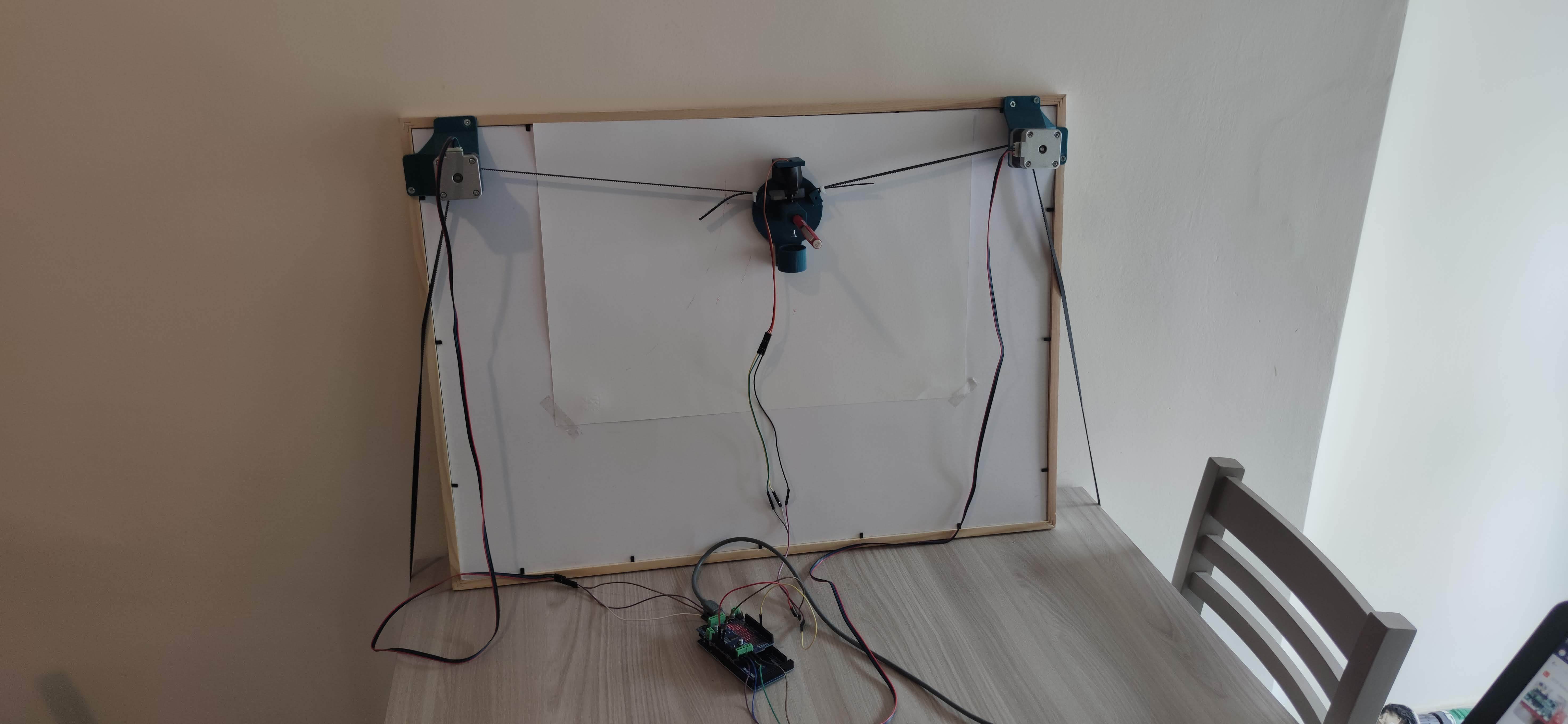
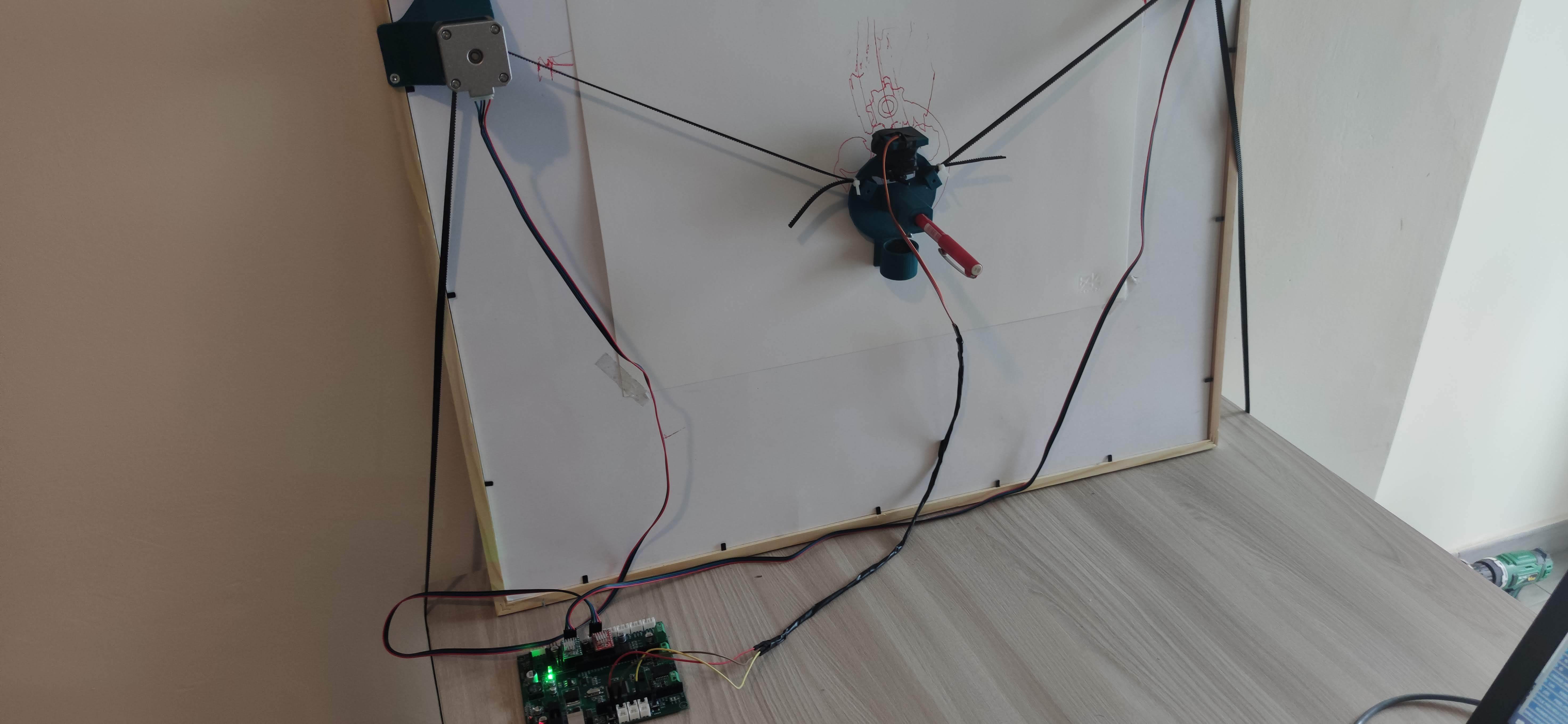
We remove the Adafruit motorshield because the Drivemall board integrates everything onboard.
Moreove, thanks to the Drivemall board, you can choose different types of drivers of different quality. The difference between these drivers is appreciated on the final result in terms of less imperfections on the picture.
What We Need
Shopping list:
- 2 cable fo motor
- Vertical plotter stuff (link to the digijeunes instruct.)
- Drivemall (again, link to the drivemall instr.)
- Usb cable
- 2 Driver A4988
How to Replace Hardware
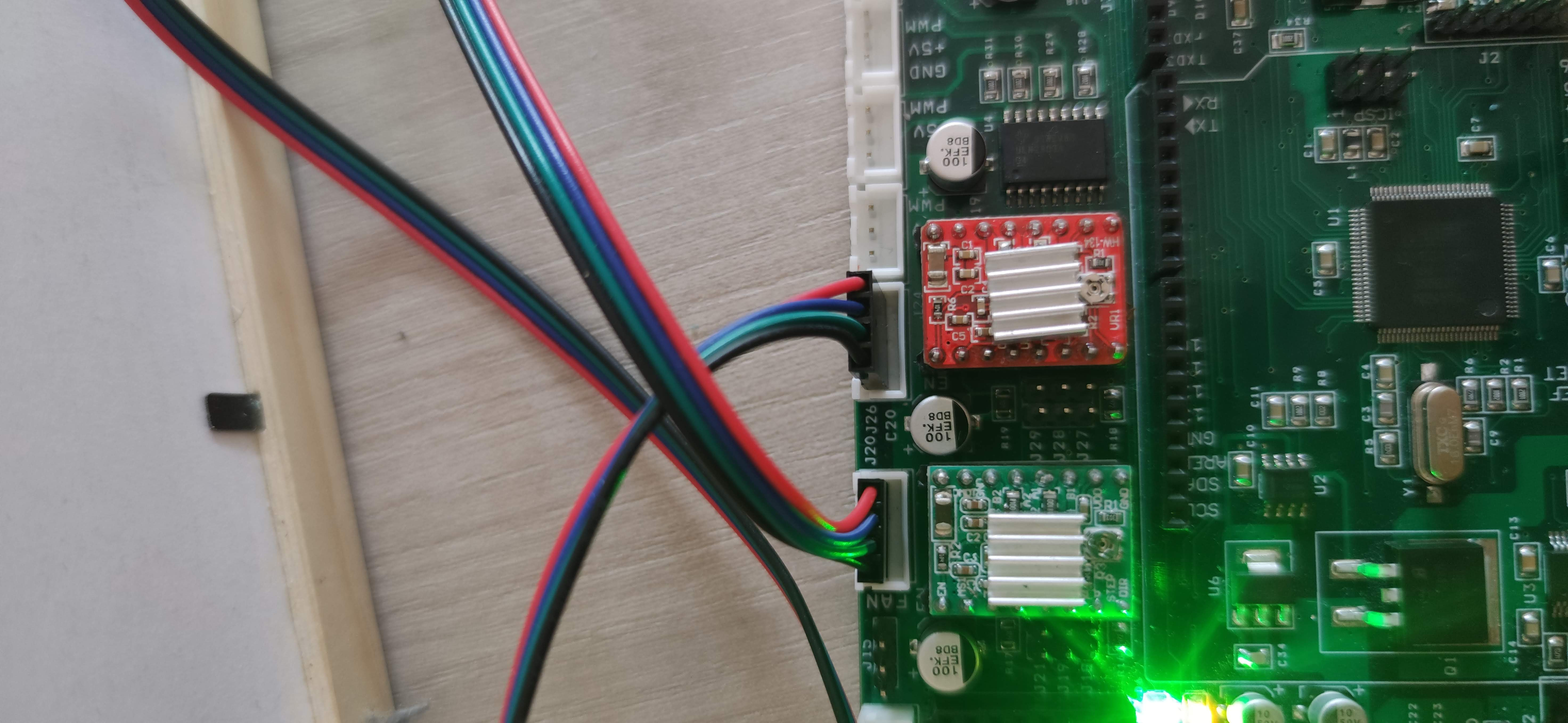
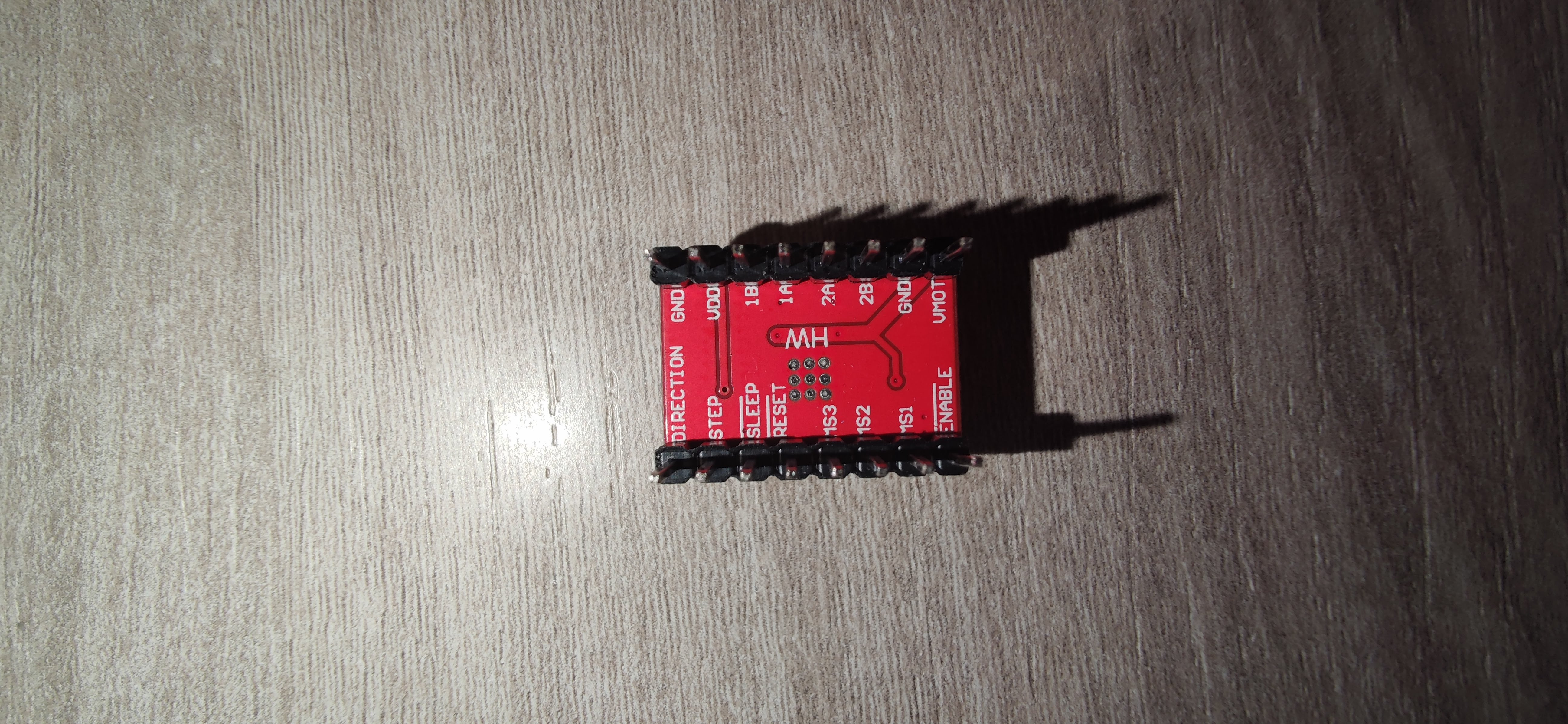
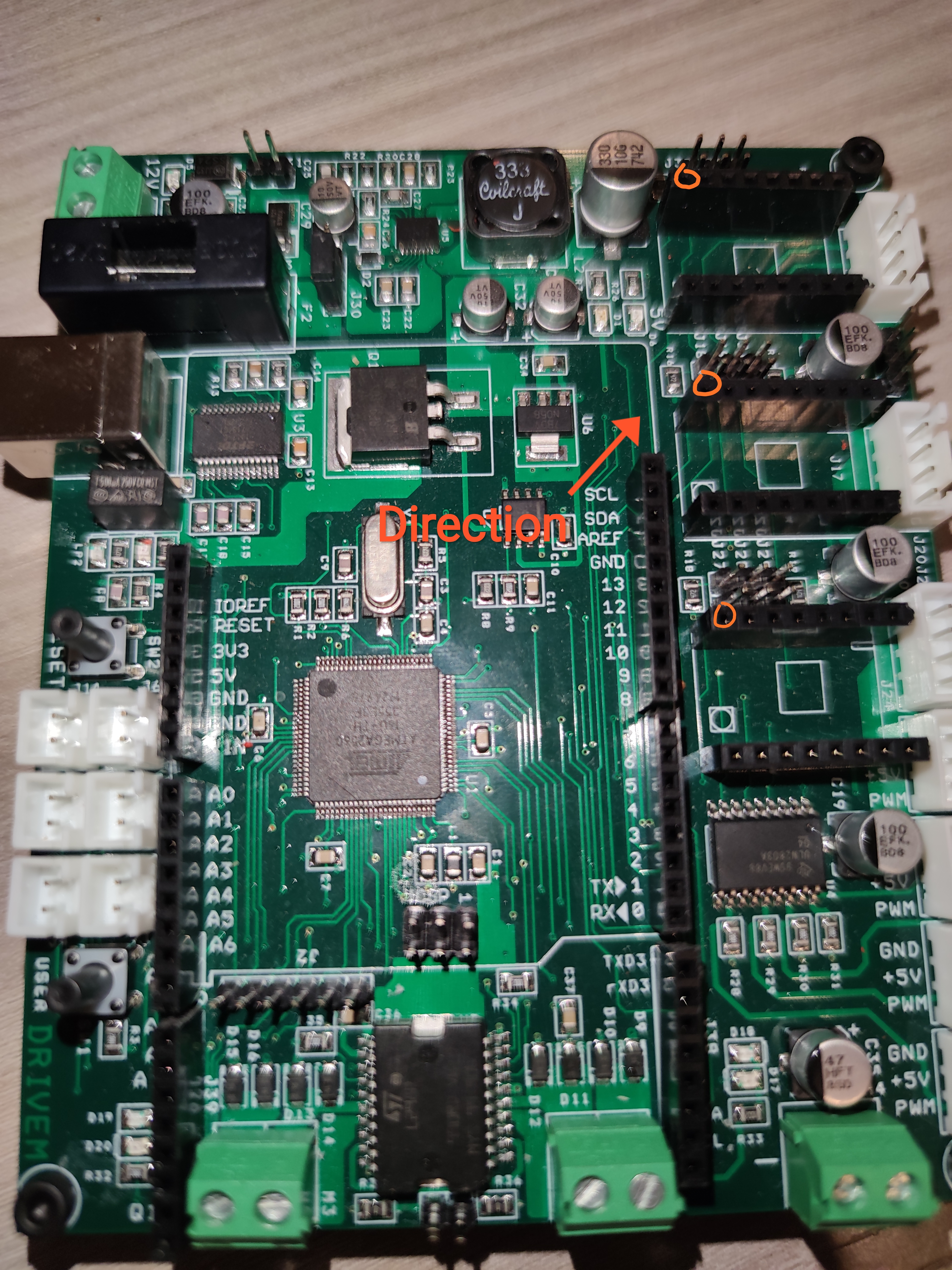
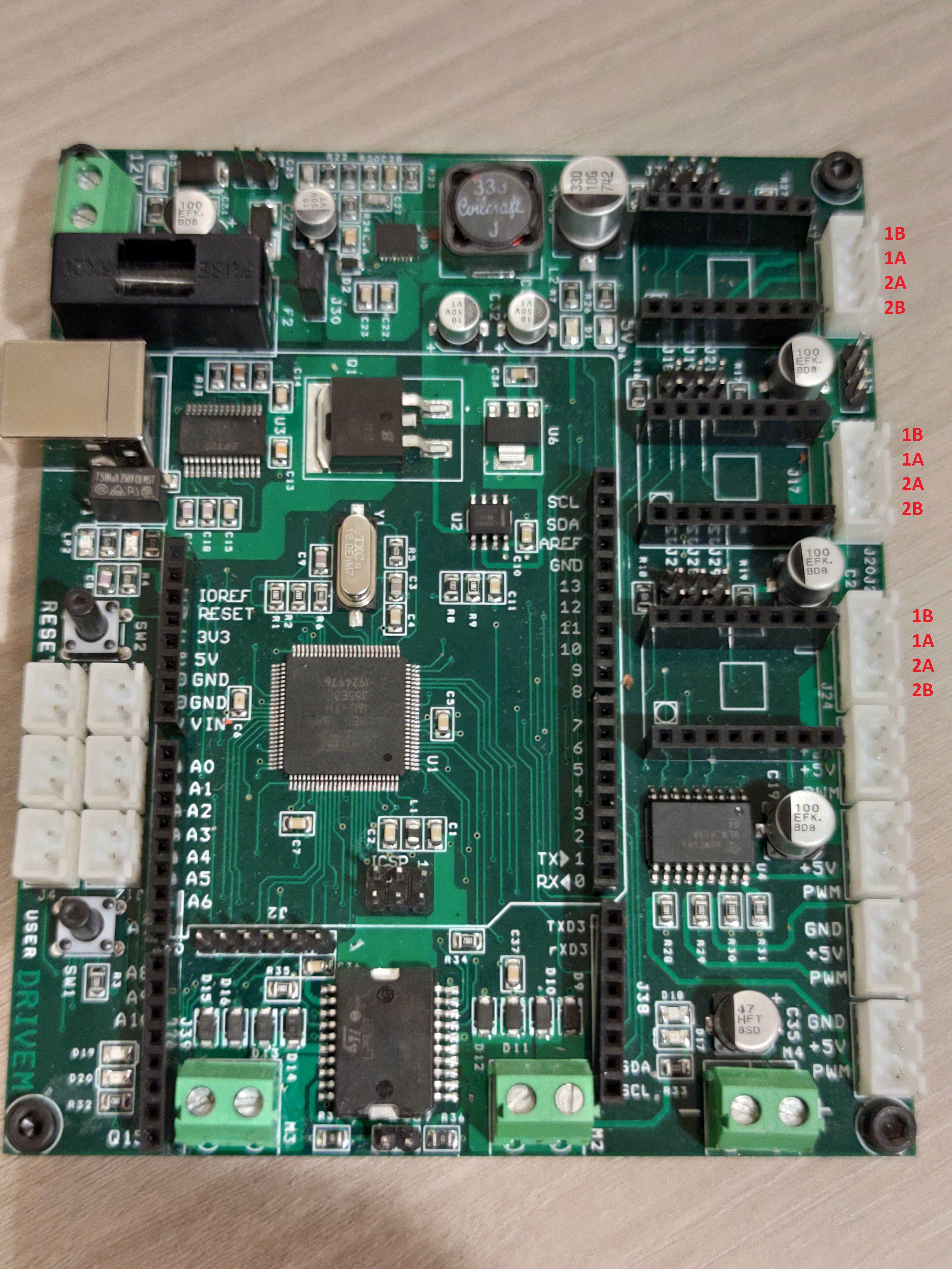
We need to remove the Arduino Uno controller and the Adafruit Motor Shield V2 baord in order to replace them with the Drivem and two motro stepper drivers.
To do so, let's connect the driver Steppers in the connector J17 J24 (see the pictur 1) on the other hand, pay attention to the pin direction ( see the pictur 2, 3).
For the connection with the motor, pay attention to the phases of the stepper motor that connecting an incorrect connection can destroy the driver. The Driver A4988 have the pin has the motor pins in the sequence 1B 1A 2A 2B.(see the pictur 4).
The servo is connected to the pins VDD GND and A3.
Firmware
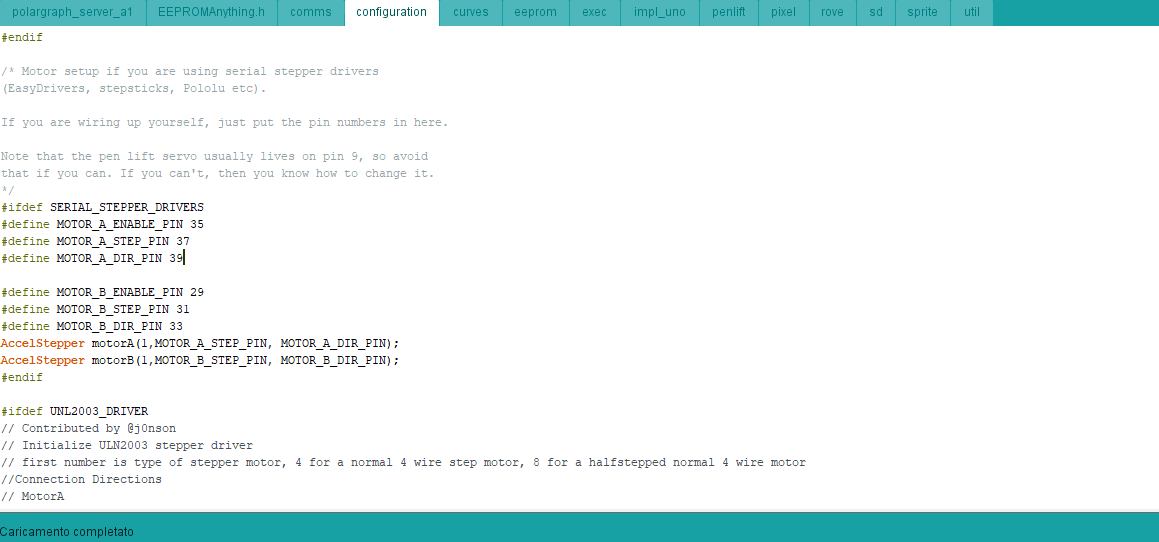
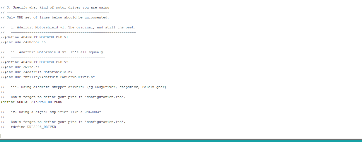
Now it is time for programming!
There are some little differences in the firmware because the Adafruit Motor Shield V2 board is controlled using the SPI bus, on the other hand, the Drivemall uses the Step drivers (A4988) controlled with two PIn STEP in PWM e Dir for direction.
Thus we need to send the correct instructions to the drivers which will take care of the steps for rotating the motors.
Here you can find the firmware attached
Downloads
Drawing
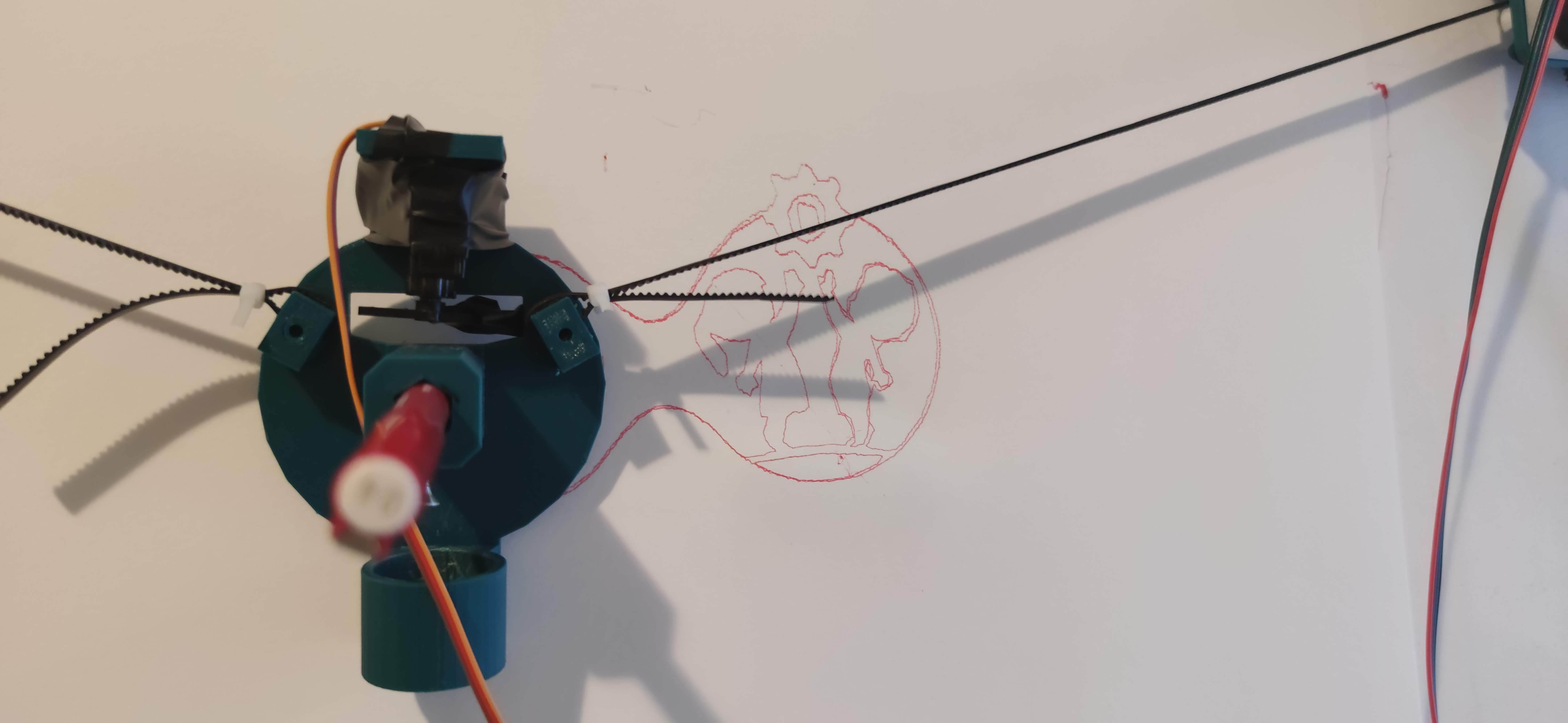
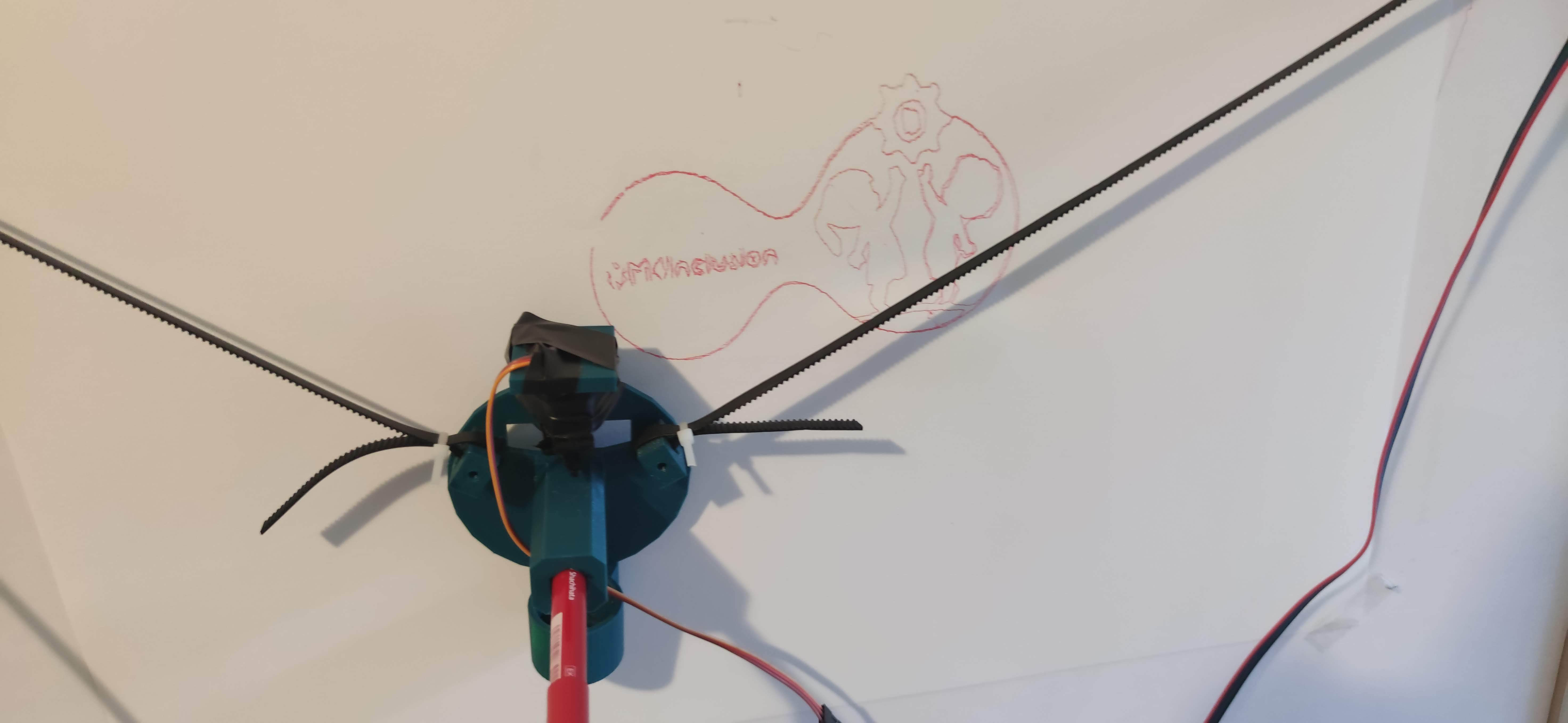
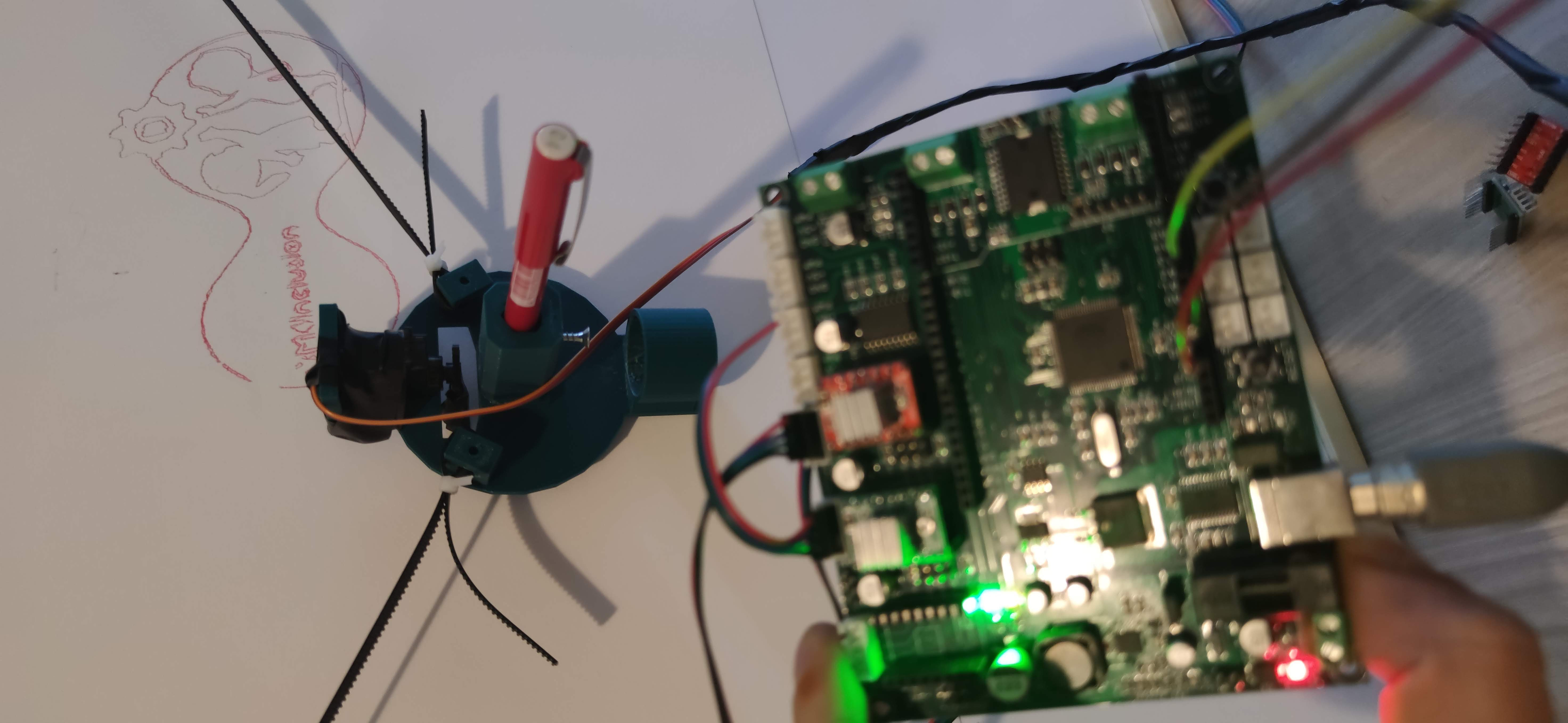
OK, it should be everything done. We can now draw a sketch!
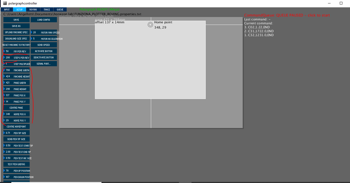
To use the plotter we use Processing by setting the size of the plotter and the working air in Setup and in particular the number of steps per revolution and the millimeters traveled by the tip per revolution.
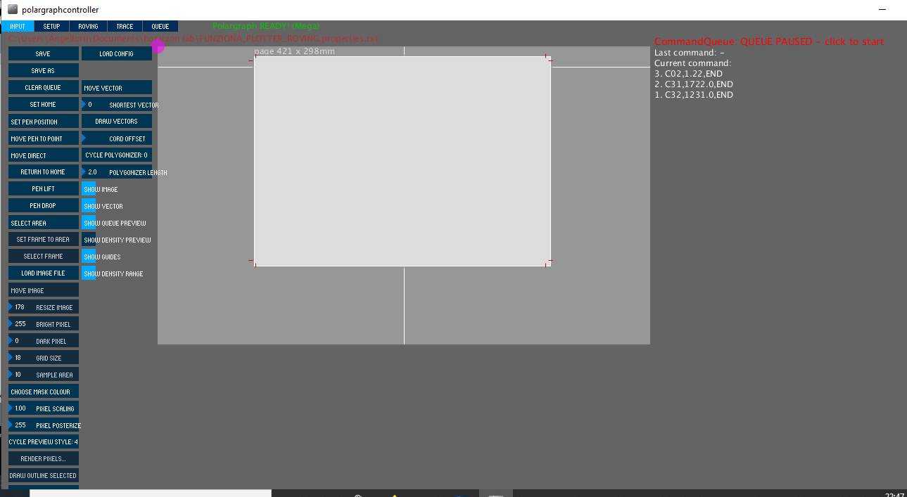
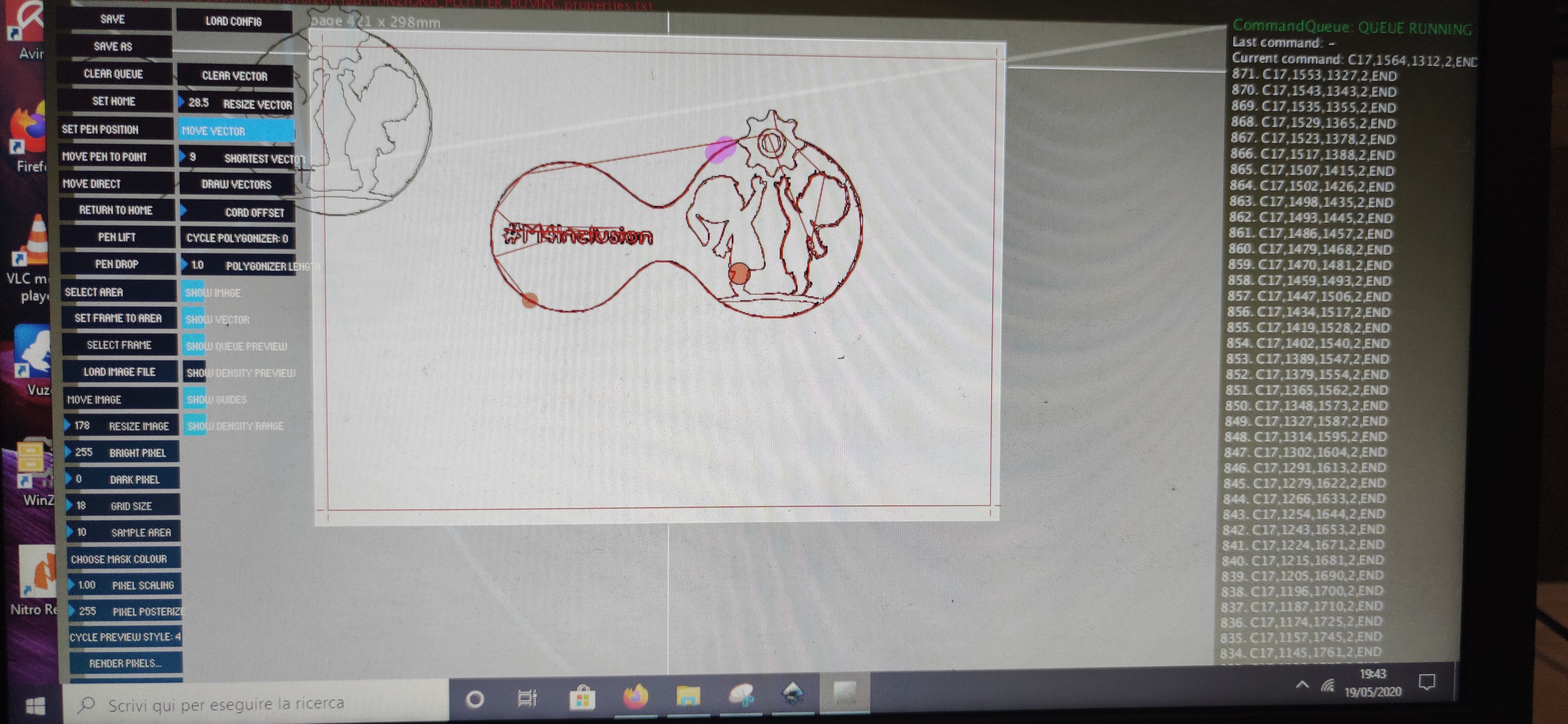
Let's go to Input, click set Home and go to load the image using load vector.
To improve the accuracy of the plotter we can decrease the speed and acceleration.
Conclusion
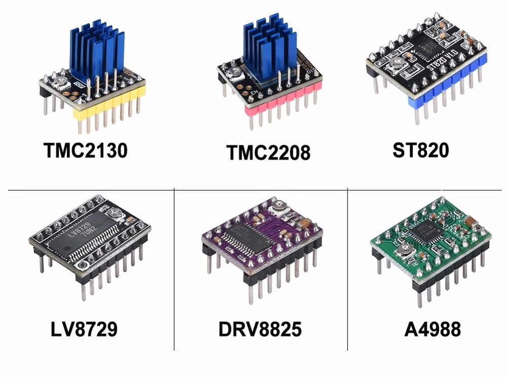
The use of external stepper drivers allows making the noise of the motors interchangeable with other types of drivers that offer greater precision, for example, the tmc2208