Variable Breadboard Power Supply
by Makertronics in Circuits > Tools
11246 Views, 177 Favorites, 0 Comments
Variable Breadboard Power Supply


Power supplies are the most basic tool every DIY / maker / electro-enthusiast should have. While the lab bench power supplies are great but you can't carry them everywhere and that's why you need a portable power supply, but they are generally restricted to 12-volt & 5-volt battery pack and to create a variable supply from that you need some circuitry which consumes some space in the breadboard. Also, the variable supply made with LM317 type linear regulator can't provide enough current, and because it is a linear supply it wastes a lot of energy and can't provide output voltage greater than the input.
In this Instructables, I am going to show how I created a portable compact and efficient variable power supply that can provide from 0 volts to 30 volts with 1.5 amperes using very few components.
Supplies


- 3 Digits Digital Voltmeter
- XL6009 Buck Boost Module
- 7805 Regulator SMD
- 10K Ohm Potentiometer
- 10uF / 100uF Electrolytic Capacitor
- 10nF Ceramic Capacitor
- Male/Female 2.54 Headers
- SPST Power Switch
- 5mm LED and Resistor
- DC Barrel Jack
- 12V AC/DC Adapter
and some 3D Printer Parts.
For PCB Manufacturing (If you preparing PCB yourself)
- A4 Glossy sheet
- Copper Clad
- FeCl3
- Marker and Laser Printer
Circuit / Schematic Design

As Most of the circuits use 5 Volts so we are going to include a constant 5-volt rail which will also power the voltmeter and the second rail will have the variable supply and for that, we are going to use XL6009 Buck-Boost Converter Module, which can convert input ranges from 3V-24V to 1.5V-30V. This range is pretty much all we need from a power supply in a general scenario.
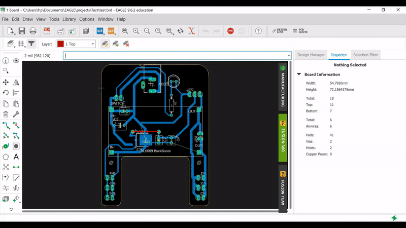
PCB Design in Eagle CAD
.png)
We are going to use Eagle CAD to convert our schematic to PCB, as later we are going to use the PCB file for creating the enclosure for our project so we will also add 3D models of all the components using the Eagle CAD's managed Library feature we can also add external 3D Models for components and there are a ton of preloaded 3D files on library.io platform associated with Eagle CAD's Components 3D Model editor.
If you want to learn more about manipulating 3D components there are some awesome tutorials at Eagle CAD's Youtube Page
For the design, we will need the dimensions of the Breadboard so as to accordingly space the headers will fall into the power rails of the breadboard.
Also, we will leave the space in between the rails so we are able to use those points.
There are two sizes of breadboard available in the market, I have made this version for the smaller one as they are widely available in my local area. But if you want to make one for the larger ones you just need to edit the dimensions outline of the .brd file given below according to your breadboard size.
Exporting 3D Model of the PCB
.png)
.png)
.png)
Fusion Sync feature available in the Eagle CAD allows you to directly export the 3D model of the PCB to the Fusion 360 project and also the same 3D model will be refreshed as you work upon it later.
No worries if you don't have Fusion 360, Eagle also allow to export STEP file of the PCB which can be imported in pretty much all the 3D Modeling software.
After getting the PCB File in Fusion 360 I created a case for the same.
PCB Manufacturing
.png)
.png)
For the PCBs, you can use this Gerber file and get it manufactured from Seeed Studio Fusion PCB. They take care of the entire fabrication process from PCB manufacturing, parts sourcing, assembly, and testing services, so you can be sure that they are getting a quality product. After gauging market interest and verifying a working prototype, Seeed Propagate Service can help you bring the product to market with professional guidance and a strong network of connections.
It's just a matter of a week or two when you receive your PCB you can continue with it.
I choose to go old school and manufacture PCB on my own using Toner Transfer Method. If you know it already or you are going to use any service mentioned above, then you can skip the steps below.
So first, we need to have a PCB in the desired shape for which we need a print of the design to have the outline, to do so, go to File Menu and click print and set the monochromatic and position on the A4 sheet.
Preparing the Copper Clad


Print a rough print for reference then mark an outline on the copper-clad and cut it out using a hand saw or Dremel. It's a little tricky to cut out the internal cavity if you don't have Dremel. You can also use a wire saw for this purpose.
After you get the rough shape, fillet the corners using a file to create nice rounded corners.
to continue with the toner transfer process you need a clean PCB as copper gets easily oxidizes in air, use some high grit sandpaper to clean/remove the top oxidation layer till you see shiny copper.
Toner Transfer


Print the same circuit on glossy paper, don't invert while printing as the layer we are going to print is of the back layer and after the transfer, it inverts itself.
Align the clean copper piece on the print such that it covers all the printed area and use some masking tape to stick it so it doesn't get misplaced during the process.
Use some hot plane surface like clothing Iron, or hair straightener and press the PCB with it for at least 5-10 minutes.
Now put the print in water to soak for a while (carry it carefully as because of the last step copper will be quite hot).
After soaking remove the glossy sheet from the paper, and you will see only the ink sticking to the copper which will prevent the copper from etching in the next process.
Correcting the Errors


There might be chances some of the traces got broken during the removal of soaked paper, no need to worry until a major portion of the print is missing.
To correct the missing traces you can use a permanent marker to join the traces according to the design file.
Similar to toner, a layer of permanent marker ink also prevent the etchant to remove the copper.
Etching


Now you are ready to etch the PCB, take some FeCl3 solution or powder and add a little hot water to speed up the process or you can also put the container on some hot plate to speed it up, and agitate it.
It will roughly take 15-20 minutes to etch away 1-ounce copper.
Once the etching is finished rinse the piece with water and clean the toner/permanent marker layer with some acetone(nail polish remover).
Now you can drill the holes for through-hole components with a 0.8mm drill bit. To make holes for DC Barrel Jack create two-three adjacent holes.
3D Print the Case

It is a 2-hour print without any supports (overhangs on both sides are designed at 45 degrees), there will be some bridging to avoid supports so make sure to adjust the parameters of your 3D Printer according to that.
You can also print the knob for the potentiometer, it is designed for the shaft of 4mm diameter.
STEP File for the project is also included in case you want to tweak some parameters.
Changing the Potentiometer


The Trimpot (Multiturn potentiometer) on XL6009 is quite tiny to control independently, which means you need a minus screwdriver to rotate it. so we will remove it will a normal potentiometer. It will definitely reduce the precision of controlling the output voltage but change the voltage won't be any hassle. Or you can implement the same design with a full-size multi-turn potentiometer.
I desoldered the trimpot and solder a JST connector in place of that and a soldered a compatible connector to the potentiometer. You can skip of all these and directly solder the potentiometer with wires to board.
Soldering XL6009 Module


The circuit is designed such that the electrolytic capacitor lies beneath the XL6009 module which is the reason why we need to use some female headers to provide appropriate height to the module.
Cut 4 Female Headers and first add them to the module and use it as a jig to hold the pieces while soldering, this will ensure that the module will fit the headers even after removing it.
Soldering the Headers


As this being a single-sided PCB, soldering male headers on such that it protrudes on the other side is a little tricky, you need to push it from the top like other components and then using a plier push the remaining on the top to the other side (so the length of pin available to insert in breadboard is enough), then solder all of them from behind as can be seen in images.
After this solder the wires to the board which will be used for the switch and connecting to banana connectors, you could also use a JST connector here but it should be a right-angled one as the height between PCB and XL6009 module isn't enough to hold a verticle JST connector.
Assemble Voltmeter & Potentiometer


After completing the soldering for all the components it's now time to assemble everything together.
The Voltmeter will need M1.5 bolts, just put the voltmeter in the slot and tighten the bolt. If you can't find the appropriate size use a glue gun to stick it in place.
Thereafter solder the wires of the voltmeter to board. If the connecting wire seems too long then cut it to 8-10 cm length then solder it.
Black is the ground, Red is for 5V and yellow is for Voltage Measuring from left to right.
Now insert the potentiometer soldered before in the solder next to the voltmeter and tighten the nut from outside.
Add Banana Connectors


The slot in the side is perfectly sized for the nut that came with the banana connector so insert the banana connector from the top and introduce the nut from behind and rotate the connector, it will tighten automatically.
To connect the wires to the banana connector strip the wire and introduce them just before the nut is about to tighten completely between the nut and the body.
Closing the Enclosure


Now that everything is installed from the inside, close the enclosure and tighten it will some 2mm screws.
While closing the enclosure make sure to bring out the wires for switch, as the switch will be soldered outside and then inserted.
If DC Barrel Jack isn't fitting perfectly in the slot, use a file to remove away the material from side and try to fit it again.
Add Switch & Potentiometer Knob


Add some heat shrink of appropriate size to the wires in order to prevent the switch connectors from shorting inside the enclosure. Solder the wires and heat the shrinks.
After that press-fit the switch inside the slot.
Woohoo! You Have a Variable Breadboard Power Supply


Finally, you got a power supply that is portable, variable, and can also be used externally without the breadboard with the banana connectors.
You can also connect any lipo battery, AC/DC adapter, or USB to Barrel jack cable to provide supply to it.
If you face any difficulties in replicating this, do comment below and I will try to help with it.