VIRTUAL ROBOT CIRCUIT | TINKERCAD
by Advik Shettigar in Circuits > Electronics
621 Views, 2 Favorites, 0 Comments
VIRTUAL ROBOT CIRCUIT | TINKERCAD

In this article I will tell you the steps to make a Virtual Robot Circuit using TinkerCad. In this circuit, when the switch is turned on, the motors will move forward.
Step 1: Components Required

The required components to make this circuit are as follows:-
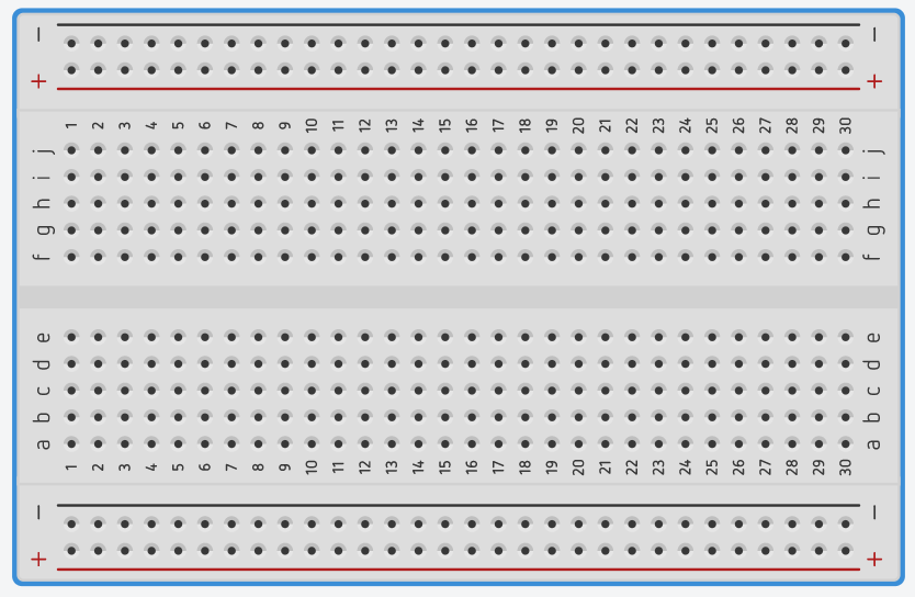
- Breadboard
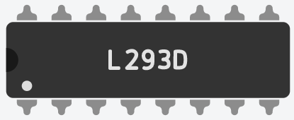
- L293D - Motor Driver
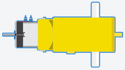
- Motors - 2 Nos.
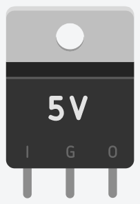
- Voltage Regulator-5v
- Battery-9v
Step 2: Connections
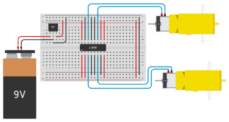
Make the connections as shown in the above picture using TinkerCad Circuits.
Step 3: Testing
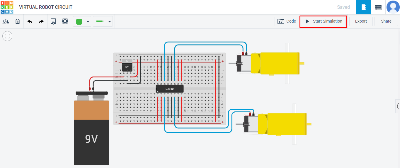
Start the simulation and notice the motors of the circuit will move in the forward direction.