V12 Engine Clock
by Will Reeve Design in Workshop > 3D Printing
1242 Views, 10 Favorites, 0 Comments
V12 Engine Clock
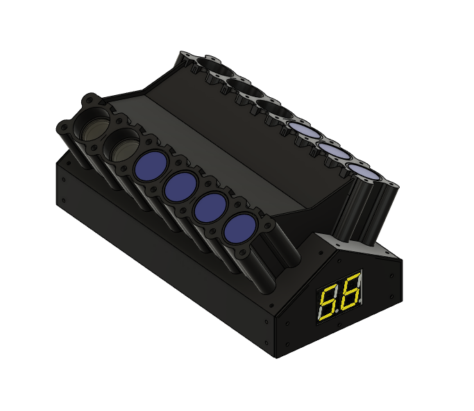


Why not recreate the concept of a clock to make it more relevant for engineers? This laser cut and 3d printed V12 clock aims to target high level engineers in a revolutionary way. It is a great coincidence that the greatest type of engine of all time matches the amount of hours on a clock. It is the perfect recipe for a clock - to tell the minutes, keeping with the beautiful simplicity of the project inspired by Colin Chapman, I have used two large seven segment displays on the front and then the light up pistons when they move upwards every hour. I started this project at the age of 13 by myself and have taught myself Fusion 360 for it. My clock and Fusion 360 have inspired me to think about the beauty of design and from this I have received an offer for work experience at a formula 1 team this summer.
Supplies


The list of items required for this V12 clock project are:
- Fusion 360 - this is the most tool in this project, I use it all the time and it is my most important tool at my disposal.
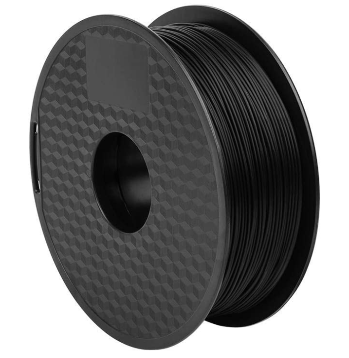
- PLA/ABS/PETG filament - This is for the main body of the engine clock and all pistons and mounts.
- 3D printer - This is required for this project, unlike a laser cutter it is very difficult to hand build the pistons and cylinders. If you don't have access to one, I highly recommend the Creality Ender 3 range. This project was made on a Creality Ender 3 V2.
- Laser acrylic - this is for the main edges on the clock. This could be made by hand, but if you have access to a.
- Laser cutter - you must use it as the finish will be significantly better on your final project.
- Arduino Mega - This is the brains of the project. Originally I used a BBC micro bit that I got given at school. I used a 16 servo controller board - do not use this, it will fry your servos.
- 7 segment large LCD displays - These are for displaying the minute time on the clock. They are wired straight to the Arduino Mega.
- 12 9g micro servos - These are for moving the servos up and down by rotating the connecting rods. They are also wired straight to the Arduino Mega.
- Jumper wires - These are for the wiring of the Arduino.
- Battery packs - You will require 2 battery packs, one 12V pack to power the Arduino Mega and 1 portable USB phone charger for the LED strip lights.
- 3D printer snipers - Again, these are not 100% needed but they are very useful for taking the supports of the prints which will be required.
- USB LED strip lights - These are needed for the lighting on the clock. It's your choice what type and they run of the portable USB charger.
- M5 bolts - You will need a pack of m5 bolts to hold the clock together.
Prototyping


The first step on this project was to test the parts. I tested the pistons and the connecting rods and the pins to connect them. I tested the servos in a brace. If you want to test these, you can use the attached files for the pistons, connecting rods, pins and cylinders.
Manufacturing of Components

Use the attached file from Fusion 360 to 3d Print all the parts. The list of parts is as follows:
3D Printing:
- 12 pistons
- 12 piston covers
- 8 centre cylinders
- 4 side cylinders
- 56 cylinder connecting pins
- 36 piston linkage pins
- 12 connecting rods (servo)
- 12 connecting rods
- 14 laser body supports (7 different types in design)
Laser cutting:
- 11 solid colour laser pieces
- 1 clear edge piece
- 12 piston covers (numbers optional)
Downloads
Programming and Wiring of Servos and LCD Display


For this stage, program the Arduino Mega to control the servos and LCD display. Every clock is bespoke so my code must be made for the individual clock needs. Make sure to complete this stage before you install the servos into the clock. I learned this the hard way. You can store the Arduino mega in the top compartment in the final product
Spraying Pistons

Make sure to spray the inside of the pistons a reflective colour like silver, this will allow the light to bounce off the inside of the pistons and illuminate the piston covers.
Assembly


Use the M5 bolts and epoxy glue to build the clock. The layout it very self-explanatory and it fits together perfectly. Use the complete model file to guide you.
Disclaimer: Do not use super glue as the residue stains the parts (I made this mistake on my clock)
Downloads
Installing Finishing Touches


Now you can install the servos, LCD displays, battery packs, Arduino Mega and LCD strip lights into the clock.
The servos, LCD displays and strip lights are required to be installed into set places. However, you have free reign on where you put the battery packs and Arduino Mega.
The Final Product


I hope my project has inspired you to create a clock just like mine. It is a great way of revolutionizing something as simple as telling the time. I really enjoyed making this project and I am very grateful to Autodesk for their free student licence to Autodesk software. without it I would be nowhere with this project.
All you need to do now, is simply relearn how to tell the time in a newer, better way - count the pistons that are light up and up for the hours and use the LCD displays on the front for the minutes.