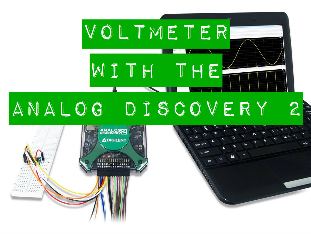
Using the Voltmeter With the Analog Discovery 2
by brmarcum in Circuits > Tools
9195 Views, 8 Favorites, 0 Comments
Using the Voltmeter With the Analog Discovery 2

The Waveforms Voltmeter tool is the simplest tool available in the Waveforms suite. With no options to decipher and set, you'll be up and running in no time.
For this Instructable you will need:

- Waveforms 2015 software

- a computer with USB port to run the software
*You may also use the original Analog Discovery or the Electronics Explorer Board with Waveforms 2015. The only difference in functionality with the Voltmeter tool between the two Analog Discoverys and EEBoard is that the EEBoard has 4 voltmeter channels while the AD1 and AD2 only have 2. Note that the Voltmeter tool is not available on the Digital Discovery.
The Voltmeter
If you want some help getting your AD2 set up and calibrated, or installing Waveforms 2015, check out this quick start I'ble collection.
Once you have your AD2 and Waveforms all set up, open the Voltmeter tool by clicking on the "Voltmeter" button.

The Voltmeter window will open.

There are two main areas: tool options are at the top, and then the voltmeter channels take up the bulk of the window space.
At the top you have a few options.

"File" lets you Save the current Voltmeter project, Open a saved project, Export the current window data, or Close the Voltmeter tool window.

"Control" gives access to the tool's Run and Stop commands.

"Window" lets you browse between any Waveforms tool windows you may have open, as well as the Help screen.

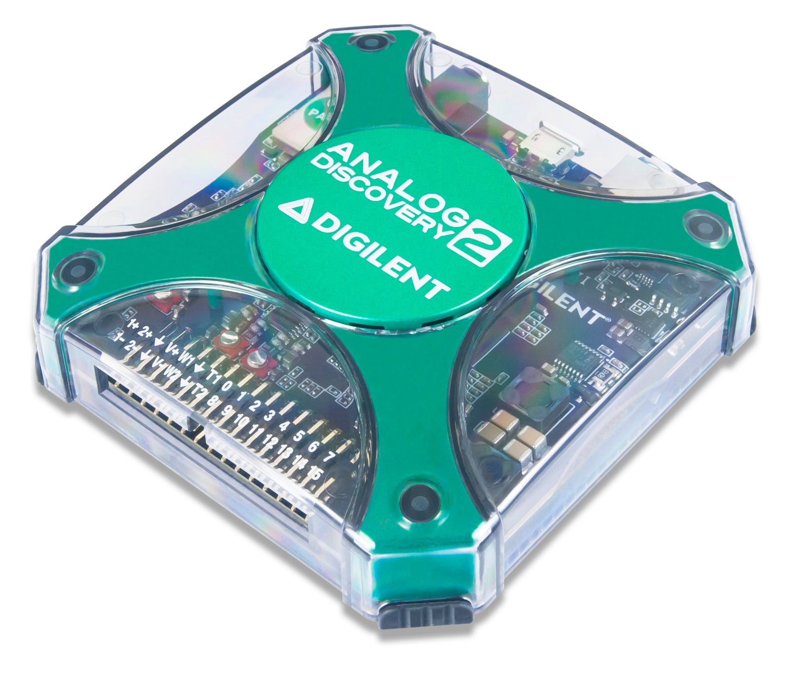
The Voltmeter tool uses the same pins that the Oscilloscope tool uses, namely the 1+/1- pins for channel 1 and the 2+/2- pins for channel 2. Simply connect the pins across the element in your circuit where you wish to measure voltage. The AD2 scope pins are fully differential, meaning that the +/- pins can swap orientation. If the signal is inverted from what you expected, be sure you have the "-" pin connected to the side of the element where you expect the lower voltage to be. The "+" pin would then connect to the side of the element where you expect the higher voltage to be. The DC voltage, True RMS, and AC RMS will all be displayed in the Voltmeter window.

The data shown above was collected using the EEBoard's Power Supplies and Waveform Generator tools and the AD2's Voltmeter tool. Channel 1 shows a nominal DC voltage of 3.3 V, while channel 2 shows an AC sine wave at 5 Hz frequency, 1 V amplitude, and 20 mV DC offset. Note that the data correctly shows the RMS value of 1 V / √2 ≈ 710 mV.
To use the Voltmeter tool on the EEBoard, use the oscilloscope pins located in the SCOPE block.

The channels on the EEBoard are not differential, meaning that the GND connection in the SCOPE block is tied to the EEBoard's internal GND plane and should be connected to your circuits's GND as well. This means that any voltage readings will be in reference to the circuit GND. If you want to read the voltage across a specific element within the circuit where neither pin is directly connected to GND, use two different scope channels and note the difference between the two.
Also, be aware that there are additional pins labeled VMTR in the ANALOG block.

These pins are not connected to the Voltmeter tool, but are connected to the voltmeter function within the Power Supplies tool. Please see that I'ble for how to use that functionality.
That's All There Is to It.
As you can see the Voltmeter tool with the Analog Discovery 2 and Waveforms 2015 software is very simple.
As always, thanks for reading. If you have questions, please ask them in the comments below, though PM's are always welcome as well. You just never know when someone else has the same question and that way we can all learn and help each other get better. Have fun building!
Also, please check out the Digilent blog where I contribute from time to time.
