Using the Littlebits HDK to Build a Tilt Sensitive Module
by MaddyMaxey in Circuits > Electronics
4582 Views, 46 Favorites, 0 Comments
Using the Littlebits HDK to Build a Tilt Sensitive Module
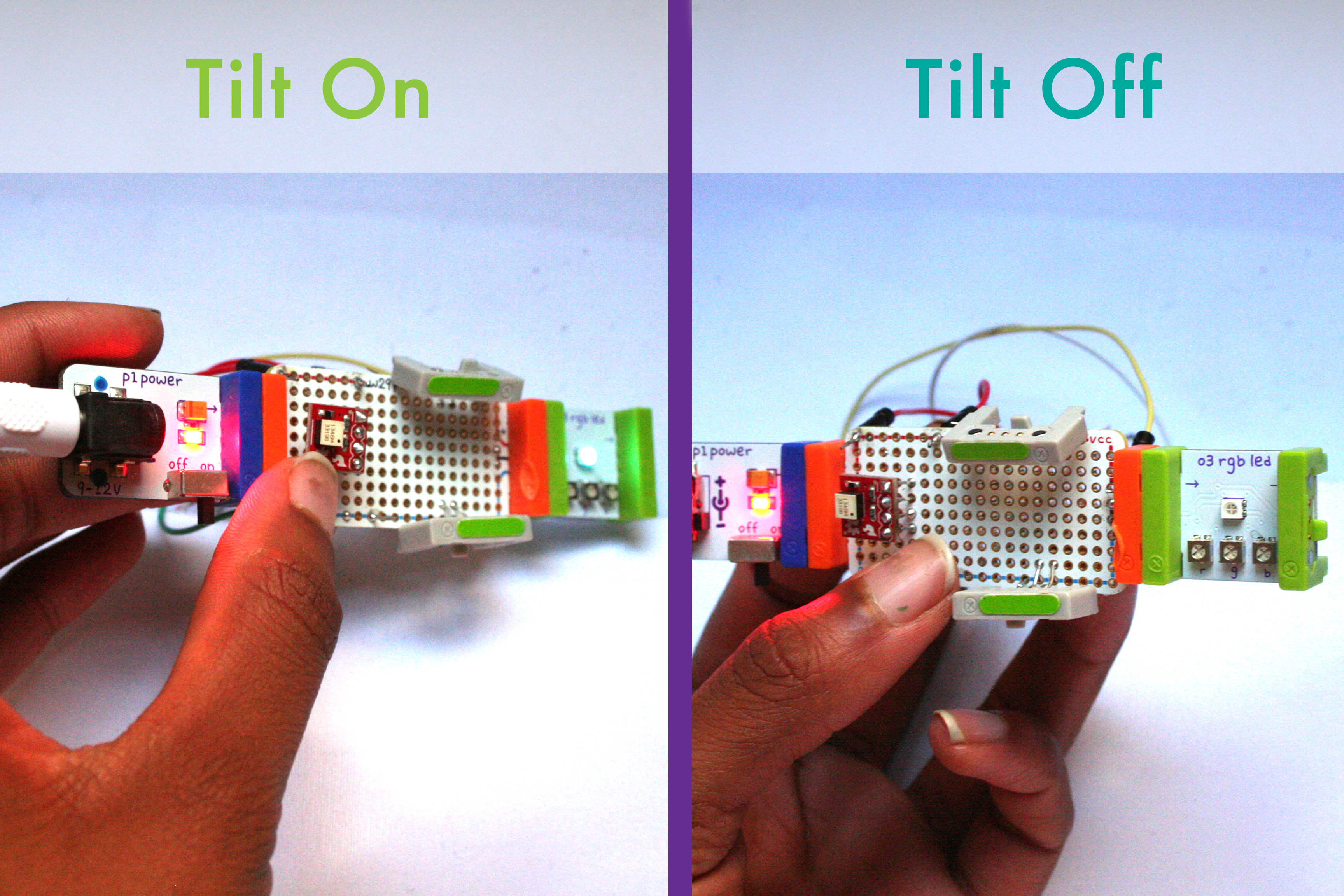
The Littlebits HDK is a useful collection of modules that help you prototype and test a module of your very own. The kit is fairly straightforward and in this tutorial, we'll be using it to create a module that senses tilt and gesture.
Materials:
- Littlebits HDK
- AtTiny85 or Arduino for logic
- Jumper cables
- Tilt-a-whirl breakout board
- Solder
- Soldering Iron
Timeline:
- One day
Get Familiar With Your Team


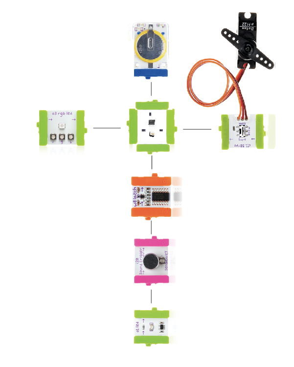
The Littlebits HDK includes three main pieces. The bitsnaps, proto module and perf module are the heart and soul of the kit. Littlebits has many-a-resource for building with this kit, so here's the essential information on getting going.
Bitsnaps: Bitsnaps come in male and female sets that allow you to make a module that snaps into the standard littlebits library.
Top tips:
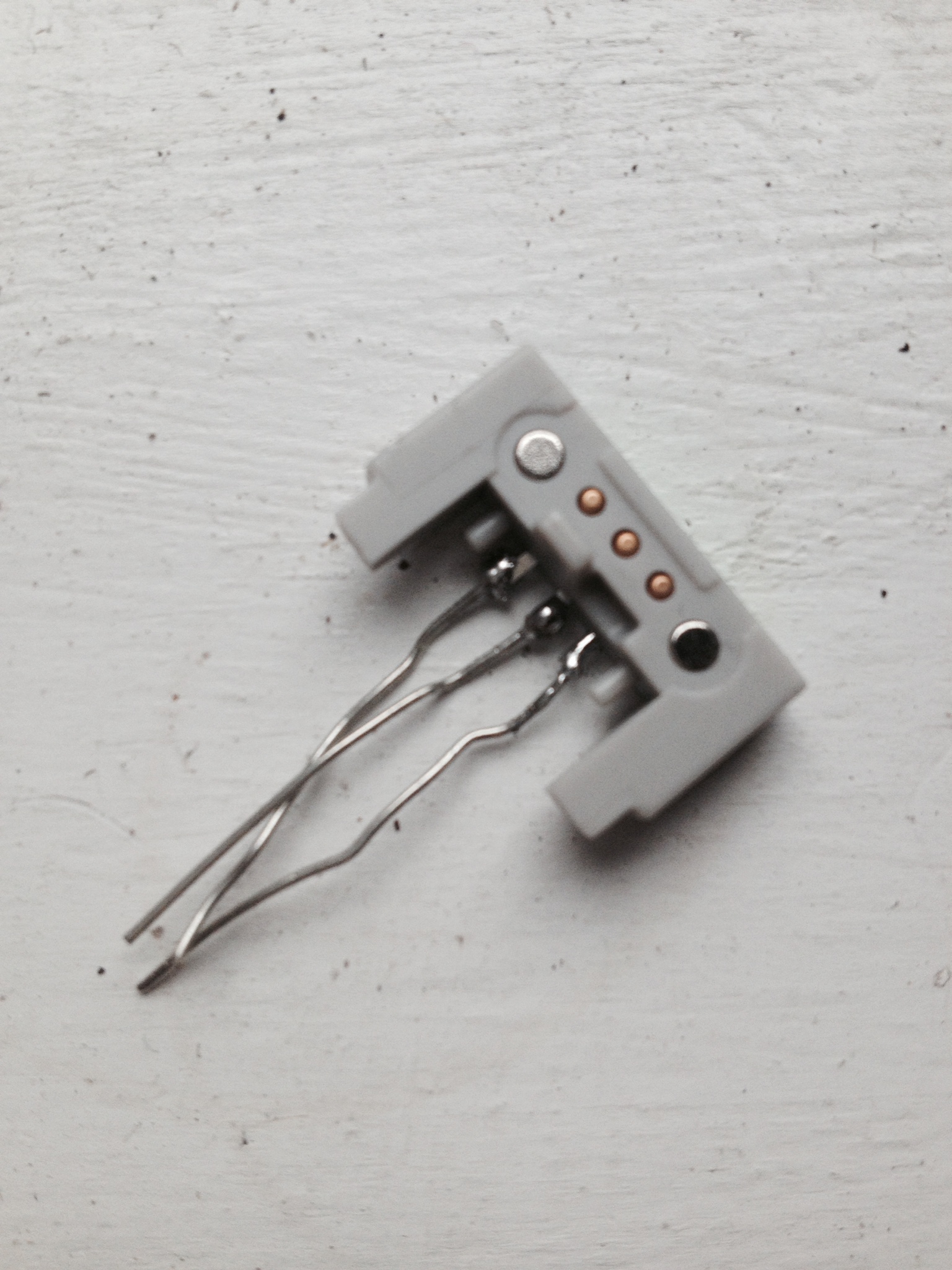
1.) These guys are magnetic, SO DO NOT TRY AND SOLDER THE LEADS WITHOUT SOME SORT OF STABILIZATION. The bitsnap will latch onto your soldering iron and it will melt the plastic.
2.) Use the stickers (also included in the kit) to keep M/F bitsnaps organized. The Signal is always center, but ground and VCC flip, running the risk of shorting your project.
Proto Module: The proto module, when combined with a multimeter, will solve all of your problems. This bit allows you to easily test the voltage running through your module and allows you to create and test temporary connections.
Top tips:
1.) Watch the Littlebits proto module how-to video. It's worth the time investment and will save you trouble in the end.
Perf Board: The perf board is a small, well, perf board with one set of male and female bitsnaps attached. To build a tilt module with three outputs, as shown in the intro, you'll need to attach one more set of bitsnaps. The perf board comes with VCC and Ground routed around the board, making wiring up a bit less dense.
Top tips:
1.) Use the preattached bitsnaps on the perfboard to ensure that any additional bitsnaps added are properly attached to VCC and Ground. I found that they acted as a visual template for attachment.
2.) For organization, I kept components on the top of the perfboard and jumper cables on the bottom. This makes the module easier to check for errors and also easier to plug into and Arduino (as I did because my ISP was broken and I simply couldn't wait for a new one).
Prepping for the Tilt Module
Materials:
- Littlebits HDK
- AtTiny85 or Arduino for logic
- Jumper cables
- Tilt-a-whirl breakout board
- Solder
- Soldering Iron
Tilt-A-Whirl - EXTEND LEADS
For this project, the sparkfun Tilt-a-whirl breakout board does quite a bit of the work for us. To prep this breakout board, you'll need to solder in 4 leads ( VCC, Ground, S1, S2).
Bitsnaps - EXTEND LEADS
You'll want to extend leads for one set of bitsnaps (m/f). Remember to hold them down* if you don't want a gloopy glop of melted plastic on your hands.
Jumper Cables - GET ORGANIZED
I used long cables for VCC, Ground and all signals exiting the board as my module's logic lives in the Arduino. If you're using an AtTiny 85 for code, You should be able to use exclusively short cables to make connections within the board.
*If you don't have a 3rd hand or a clamp, packing tape should work nicely as well.
Assembly (components)
.JPG)
.JPG)
.JPG)
If you're using an ATTiny85, assembly is a bit different than if you're plugging the unit into an Arduino. Let's begin with creating the module for Arduino, testing the code and connections, and then plugging in the Attiny!
MODULE ASSEMBLY
Additional Bitsnaps:
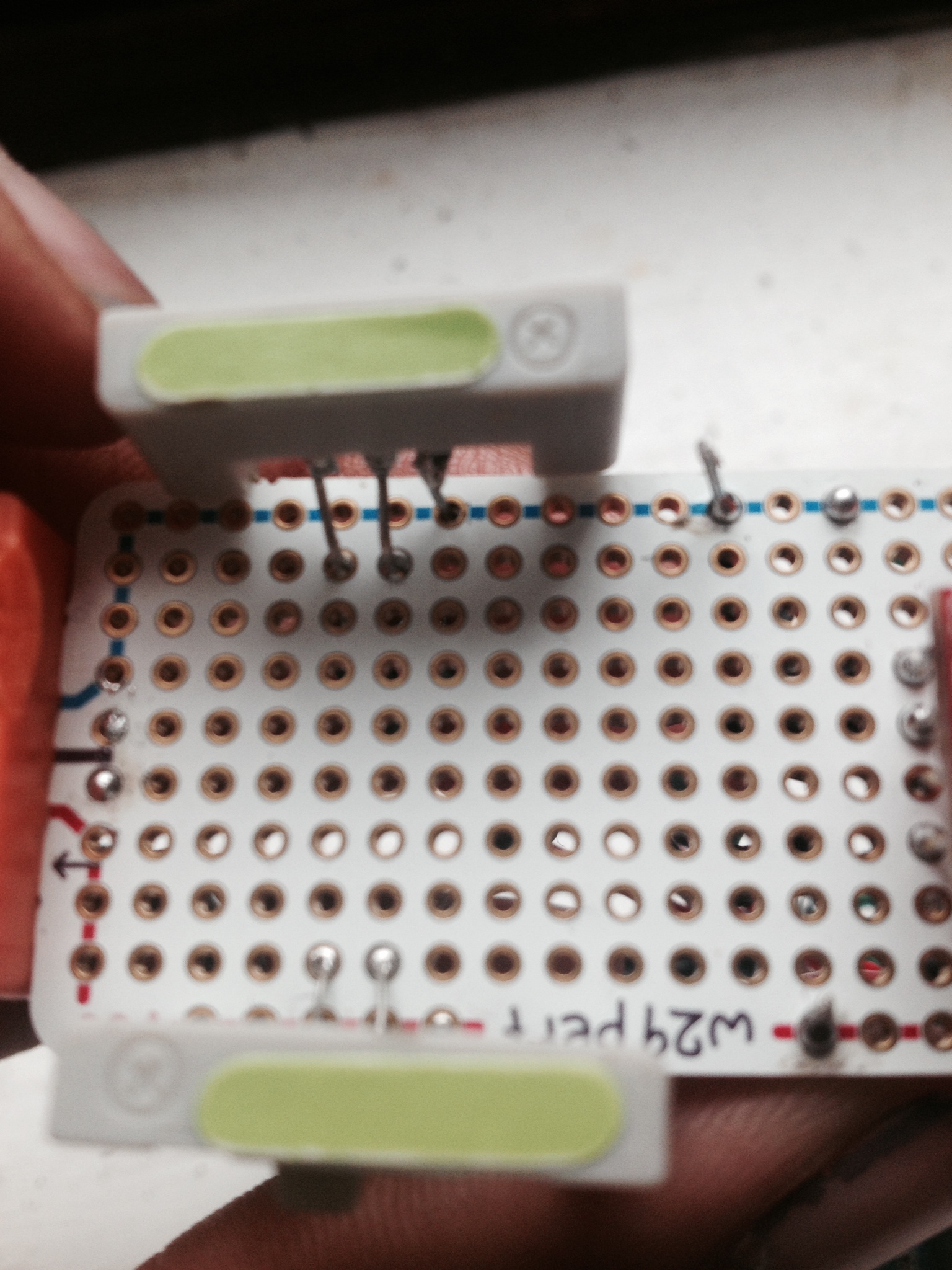
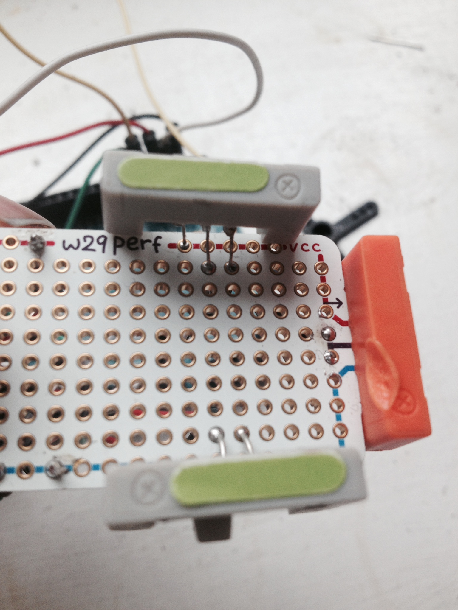
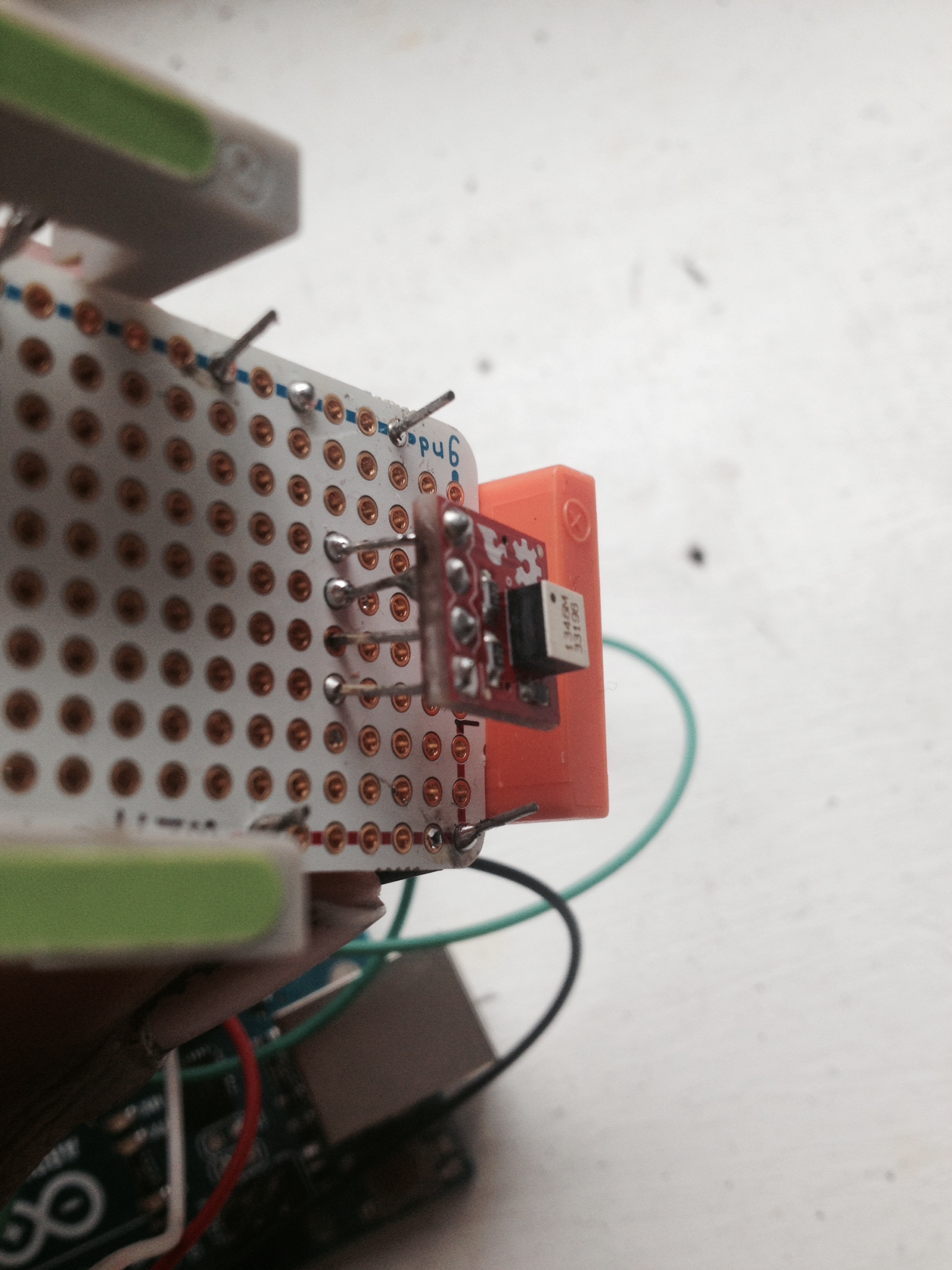
You will need to do a bit of a jig with the bitsnaps to get them properly placed on the perf board. The power leg on one bitsnap will attach to the power line on the perf board. The signal and ground legs should be soldered one column in front, avoiding the power line.
On the other bitsnap, solder the ground leg to the ground line and put power and signal one column ahead. See the images attached for a clearer demonstration.,
Tilt-a whirl
Solder the tilt-a-whirl about 4 rows in front of the input bitsnap included on the perfboard. Also see image for clarity.
*for this explanation, rows align with the short side of the perf board, columns align with the long side.
Assembly ( Wiring Up)
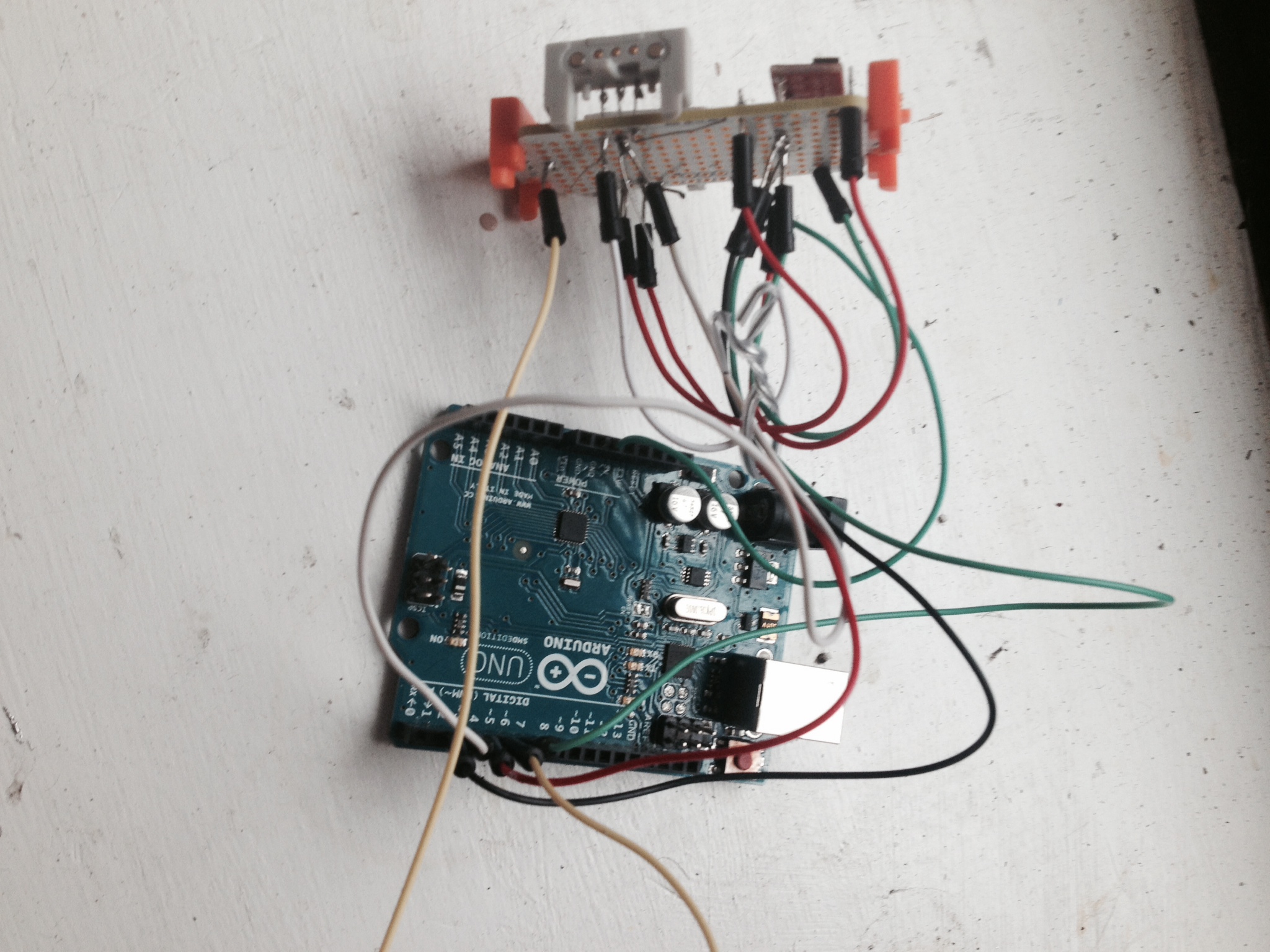
Power & Ground
Ground line :
- Grab 2 short jumper wires and 1 long jumper wire.
- Solder one side of each wire to the ground line (on the perf board)
- Wire1 (short)- Solder the other side to the ground lead on the bitsnap that does not have ground soldered into the ground line.
- Wire2 (short)- Solder the other side to the ground lead on your tilt-a-whirl
- Wire3 (long)- let this hang loose. This is grounded for the signal to the Arduino or AtTiny
Power line:
- Grab 2 short jumper wires.
- Solder one side of each wire to the power line (on the perf board)
- Wire4 (short)- Solder the other side to the power lead on the bitsnap that does not have power soldered into the power line.
- Wire5 (short)- Solder the other side to the power lead on your tilt-a-whirl
Signals
Grab 5 long jumper wires.
Wire6 & Wire7 - Solder one side of each to the signal lead on one of your bitsnaps. All leads on your bitsnaps should now be connected to power, ground and signal.
Wire8 & Wire9 - Solder one side to each signal lead on your tilt-a-whirl.
Wire5 - Solder one side to the short signal line on the pre-attached output bitsnap. The signal line is marked in purple.
These 5 wires should hang loose.
You should also have one ground wire hanging loose.
Wiring Up (plugging Into Arduino)
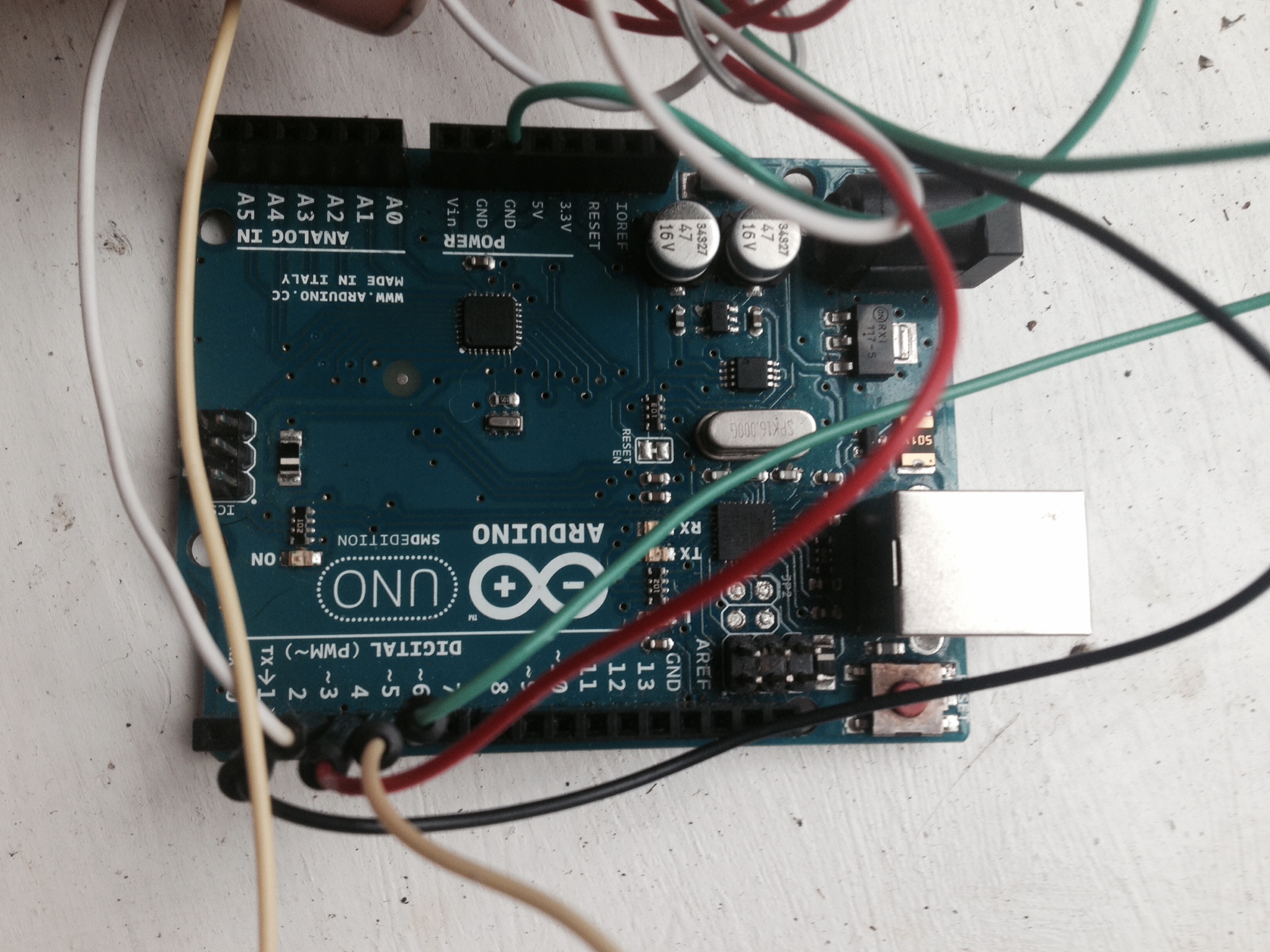
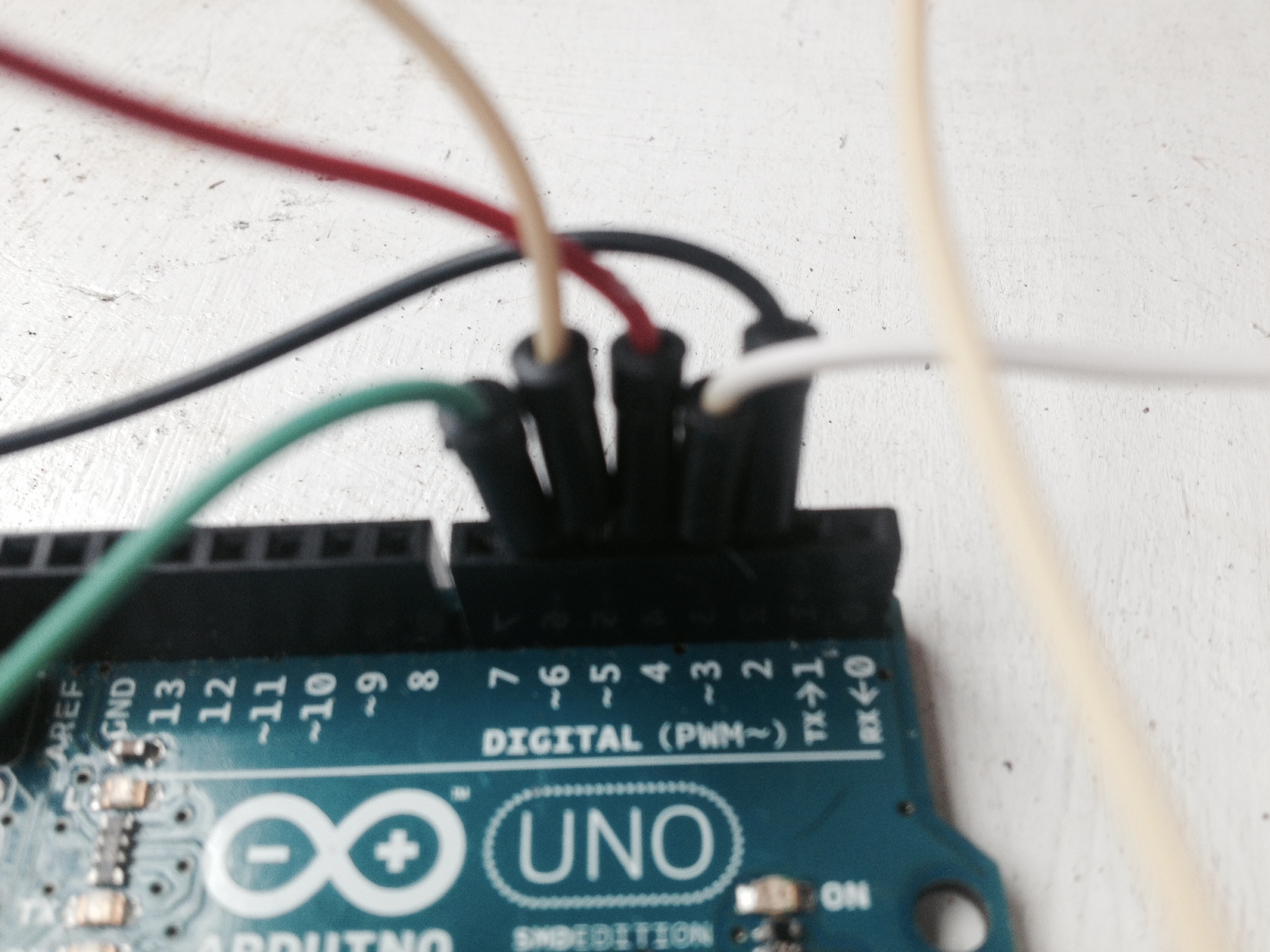.JPG)
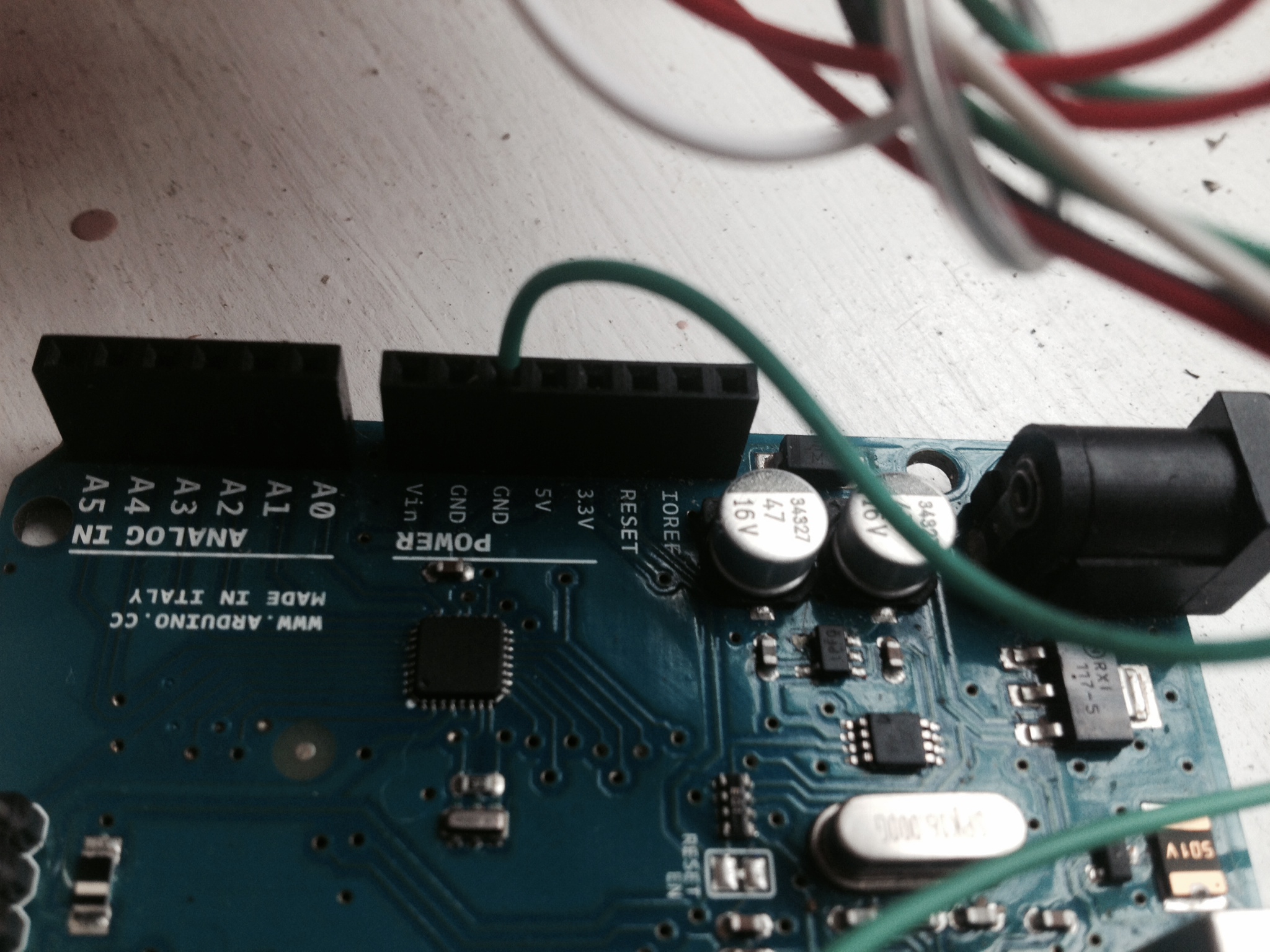
Ground
Plug Wire3 into the ground port on your Arduino. Wire3 is the only wire extending from ground on the board. You have to ground this to your Arduino or the module won't work.
Signal:
Here's a snippet from the code we will be using with wires & components mapped:
Bitsnaps
Wire5, Wire6, Wire7 // Arduino pins 3,4,5
int LED1 = 3;
int LED2 = 4;
int LED3 = 5;
Tilt-a-whirl
Wire8, Wire9 // Arduino pins 6,2
int tilt_s1 = 6;
int tilt_s2 = 2;
* Apologies for not having exact mapping. Try rerouting if your pin doesn't have the output you expected.
Uploading Logic and Making It Work!
The attached Arduino sketch *should* work. Upload and test out your routing! If things don't work as expected, try troubleshooting with the proto bit or rewiring.
When done, it should look like the module from the video.
Bonus: Using ATTiny for Logic.
The attached Arduino sketch has AtTiny pins formatted up top. You'll need to rework the code a bit, but can program your Attiny using an ISP programmer. I favor the USB ISP programmer from Sparkfun. Upload your code and you can test the code's function by plugging the loose ends of wires into the ISP ports on the programmer. Once everything is working, solder in your AtTiny onto the board (there should be plenty of space) and solder in the free wires as attached to your ISP programmer.
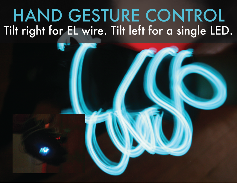
Voila! Magic! If you want to make a gesture glove as above. Simply attach the EL wire bit to the front output of your module, attach the Littlebits Battery, slip inside of a glove and get glowing!
* All images of the Littlebits HDK and modules are from the Littlebits website and belong to Littlebits, inc.