Using a Pmod ENC Rotary Encoder With LabVIEW
by Austin Stanton in Circuits > Microcontrollers
2979 Views, 23 Favorites, 0 Comments
Using a Pmod ENC Rotary Encoder With LabVIEW
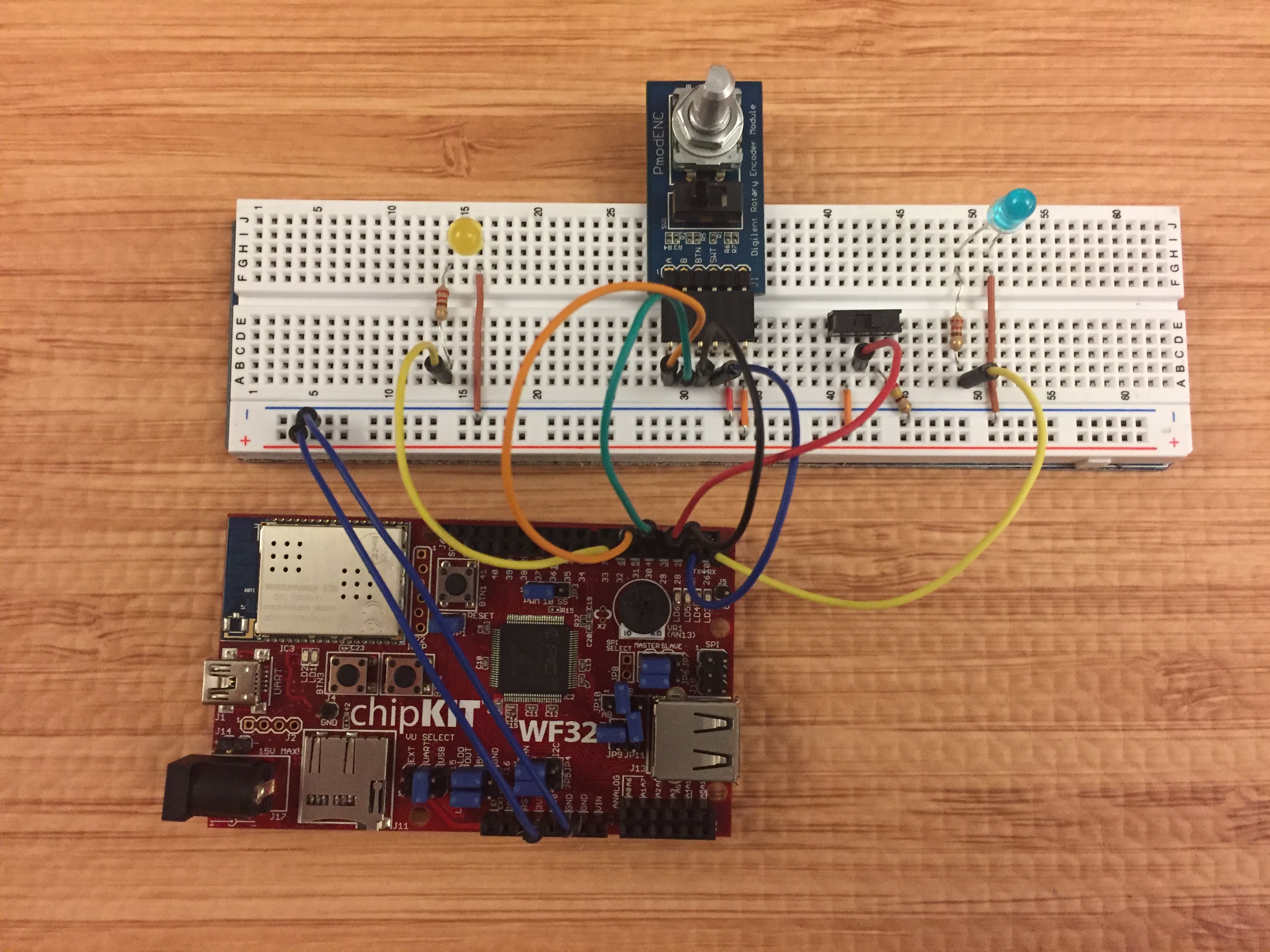
In my project, I used LabVIEW to interface with a Pmod ENC connected to a WF32. I set it up so a LED to the right of the Pmod will blink when the knob is turned right and a LED to the left of the Pmod will blink when the knob is turned left. I also have a counter that will increment when the knob is turned right and will decrement when the knob is turned left.
Materials
Hardware
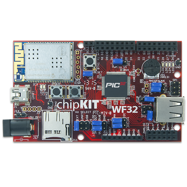
- ChipKIT WF32
- 240Ω resistor
- 2 220Ω resistors
- Slide switch
- 2 LED's
(Everything except the WF32 is included in the LabVIEW Interactions Part Kit)
Software
Circuit Setup
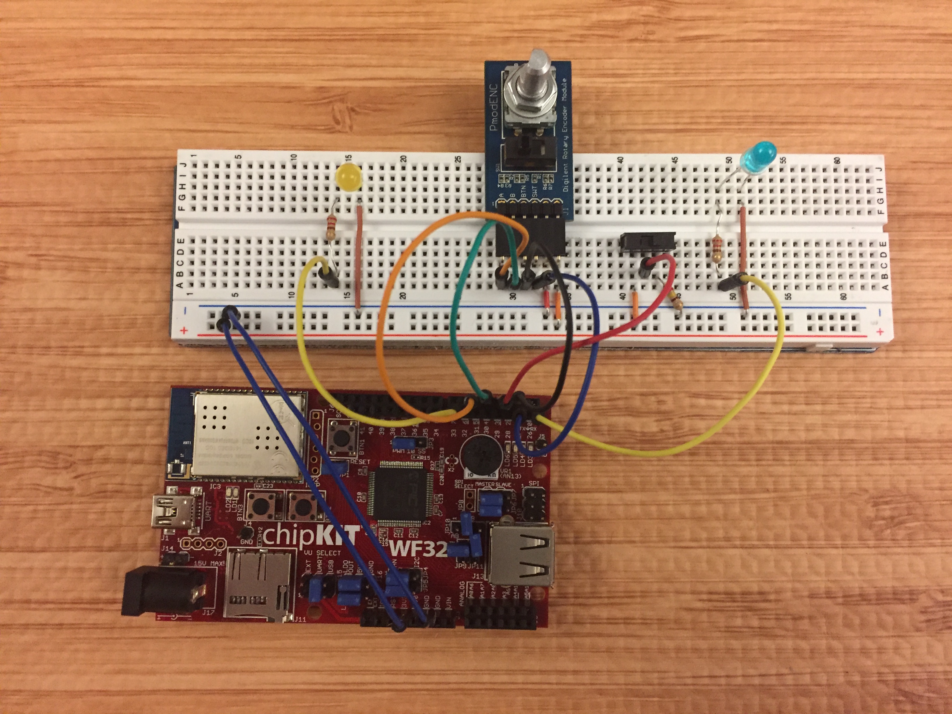
First, place the Pmod ENC in the center of the breadboard. Then, connect the 3.3V pin on the WF32 to the positive bus on one side of your breadboard and then connect the negative bus on the same side to the ground(GND) pin. Next run a wire from the voltage bus to the far right pin of the ENC and then run a wire from the ground bus to the pin directly to the left of that pin.

Next, add 2 LED's to the breadboard, one on each side of the Pmod ENC. Connect the shorter leg(the cathode) of each LED to the ground bus with a wire. Next wire 2 of your DIO pins to your breadboard(I chose digital pins 33, 26), then run a 220 Kohm resistor from each to the longer leg(the anode) of the LED. Next, place the slide switch on your breadboard, run a wire from your voltage bus to it's left outside pin. Then use a 240 Kohm resistor to connect the right outside pin to ground and then connect the center pin to digital pin 3.

Finally, connect digital pin 2 to the BTN pin of the Pmod ENC. Then connect Pin A, B and SWT of the Pmod ENC to digital pins on the WF32(I wired SWT to pin 27, A to pin 5, and B to pin 4).

Firmware Setup

Once you have Arduino IDE downloaded you will need to install the chipKIT core. The chipKIT core is a plugin for Arduino-style development environments. It contains all the files you need to start programming a chipKIT™ board with the well-known Arduino API

Refer to the instructable How to Install chipKIT Core before continuing, it will walk you through this process.
Firmware Setup

- Download the LINX_PMOD_ENC.ino file attached below
- Open this file with Arduino IDE
- Select Tools> Board > chipKIT WF32
- Select Tools> Port > then select your WF32's Com port
- Select the upload button
- Once it shows the upload is complete unplug your WF32 and then plug it back in
Downloads
LabVIEW Code
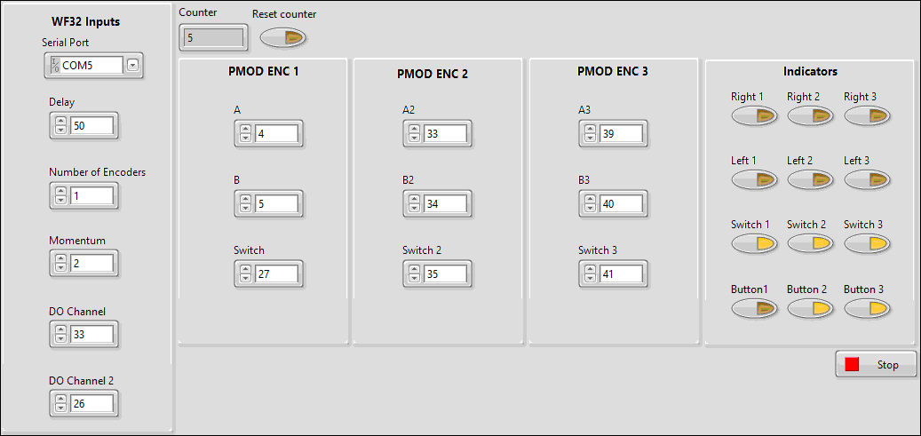
First, download and unzip and open the PmodENC_project zip file attached below. Once it is open you will see that this LabVIEW code is set up for up to 3 Pmod ENC's. In this project, I only use one so you will want to set the number of encoders to 1. The delay is used to debounce the encoder, I have found that 50ms works best. The momentum value is used to prevent bouncing from affecting your results, it is best to set this value to 2. Input your pin values for the DO channels connected to your LED's and the A, B and Switch pins of your Pmod.
Downloads
The End
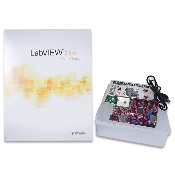
Thank you for reading my instructable, if you are interested in making this project yourself but don't have the right supplies you can purchase the LabVIEW physical computing kit with chipKIT WF32. This kit includes a copy of LabVIEW 2014 home edition, a WF32, and everything you will need to run LINX 3.0 and start making projects. Please comment with any questions or comments you may have.