Using a LCD Display Using HAL Programming
by Jugraj Shergill in Circuits > Electronics
569 Views, 2 Favorites, 0 Comments
Using a LCD Display Using HAL Programming
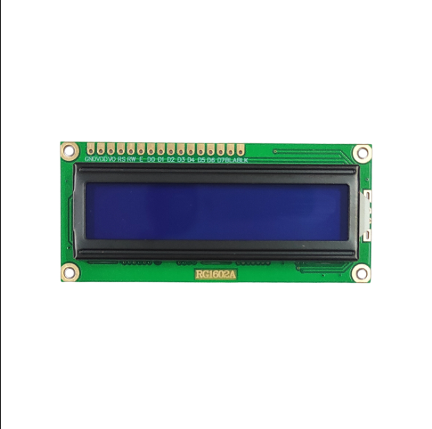

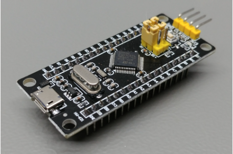
In this blog we will learn how to use a LCD Display on the STM32CubeProgrammer IDE
Supplies
- STM32 Black Pill
- LCD with I2C
- Female to Female Jumpers
- STMCubeIDE
- STMCubeProgrammer
- USB C Cable
Downloading the CubeProgrammer
In order to execute the following task we need to download the Cube Programmer IDE and then install the library files of "liquidcrystal_i2c.h" as it will have the operations and the syntax of th efunctions required to perform this task.
The file can be downloaded from the following link:
https://github.com/eziya/STM32_HAL_I2C_HD44780/blob/master/Src/liquidcrystal_i2c.h
Setting Up the STM Cube IDE
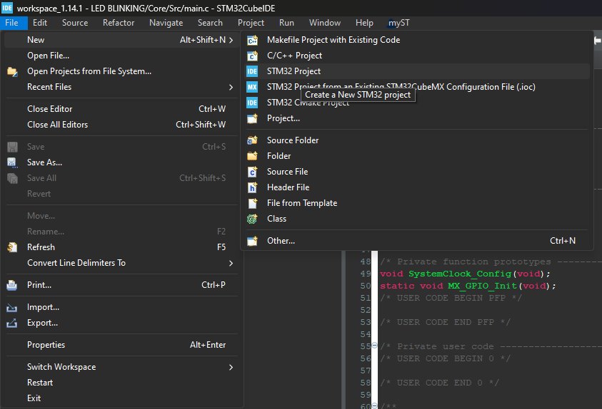
Firstly, we need to create a new project by clicking on "FILE" and then "NEW" and thereafter on "STM Projects" to get started with the program
Selecting the Pins of the Board
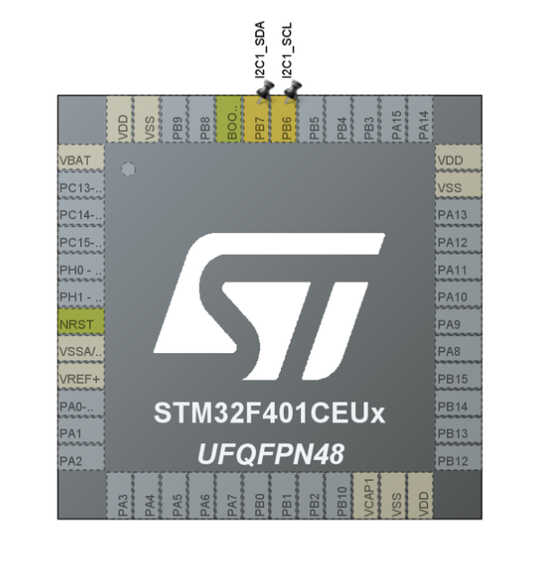
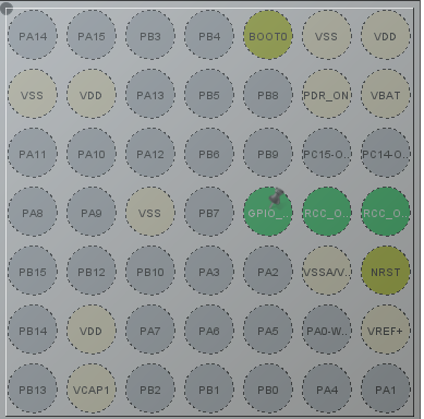
After our STM IDE project is created.
Next step is the selection of pins that we are going to connect the LCD with.
Select the pin B6 for SCL (i.e. the serial clock pulse for synchronous data) and the pin B7 for SDA (i.e. serial data transmission)
Configuring the I2C As Per Requirement
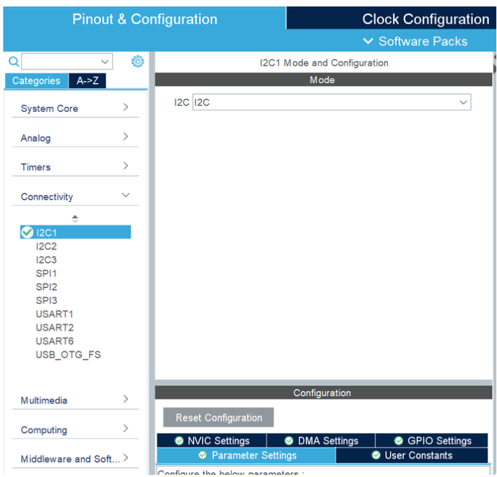
We simply configure the i2c through i2c mode under the "Connections Menu"
Clock Configuration
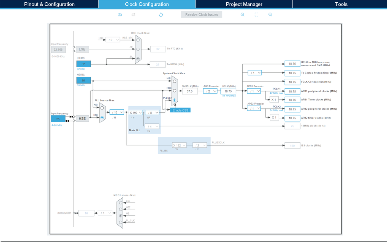
For any synchronous transmission in electronics, we require a clock signal. Creating a clock pulse is quite simple. It is done by clicking on the "CLOCK CONFIGURATION" bar right next to "PINOUT AND CONFIGURATION".
It is one of the most important steps during any task.
The required adjustments in the clock signal are done as per the picture given above.
Coding
Of course none of the asks can be completed without adding the code!
The task of coding is very much reduced in the STM32Cube IDE. To generate the code we just have to save the clock configuration and a pop up will appear as shown above which will generate the code.
Now, open the Main.C file and simply add the code given below:
#include "main.h"
#include "liquidcrystal_i2c.h"
I2C_HandleTypeDef hi2c1;
void SystemClock_Config(void);
static void MX_GPIO_Init(void);
static void MX_I2C1_Init(void);
int main(void)
{
HAL_Init();
SystemClock_Config();
MX_GPIO_Init();
MX_I2C1_Init();
HD44780_Init(2);
HD44780_Clear();
HD44780_SetCursor(0,0);
HD44780_PrintStr("Jugraj");
HD44780_SetCursor(0,1);
HD44780_PrintStr("Singh");
HAL_Delay(2000);
while (1)
{
}
}
Debugging and Building the Binary File
As the code has been created now we simply need to debug this code by clicking on "DEBUG" on the top left corner of the screen represented by a hammer and further generate the Binary File.
The binary file generation is one of the key steps in this software.
.elf File
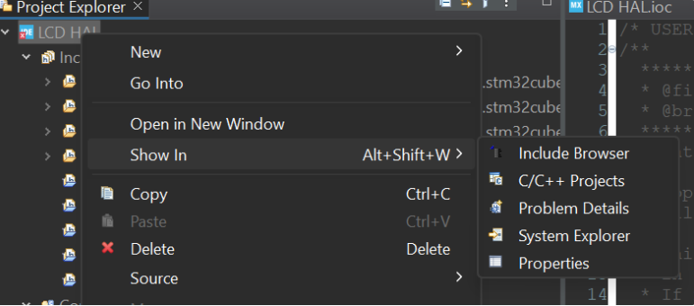
Next we simply open the .elf file created in the system explorer by Right clicking on the project and clicking on show in system explorer and copying the path on the STM32Cube PROGRAMMER.
EXECUTION!
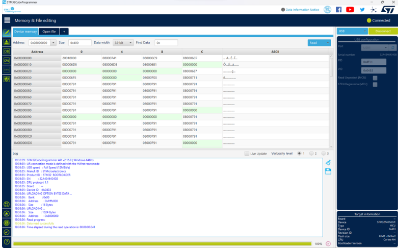
At last, connect the STM board via a USB and open the file and paste the copied path.
END!
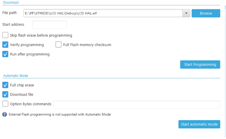
NOW just download the programs as per the instructions shown above and the results can seen.
RESULT
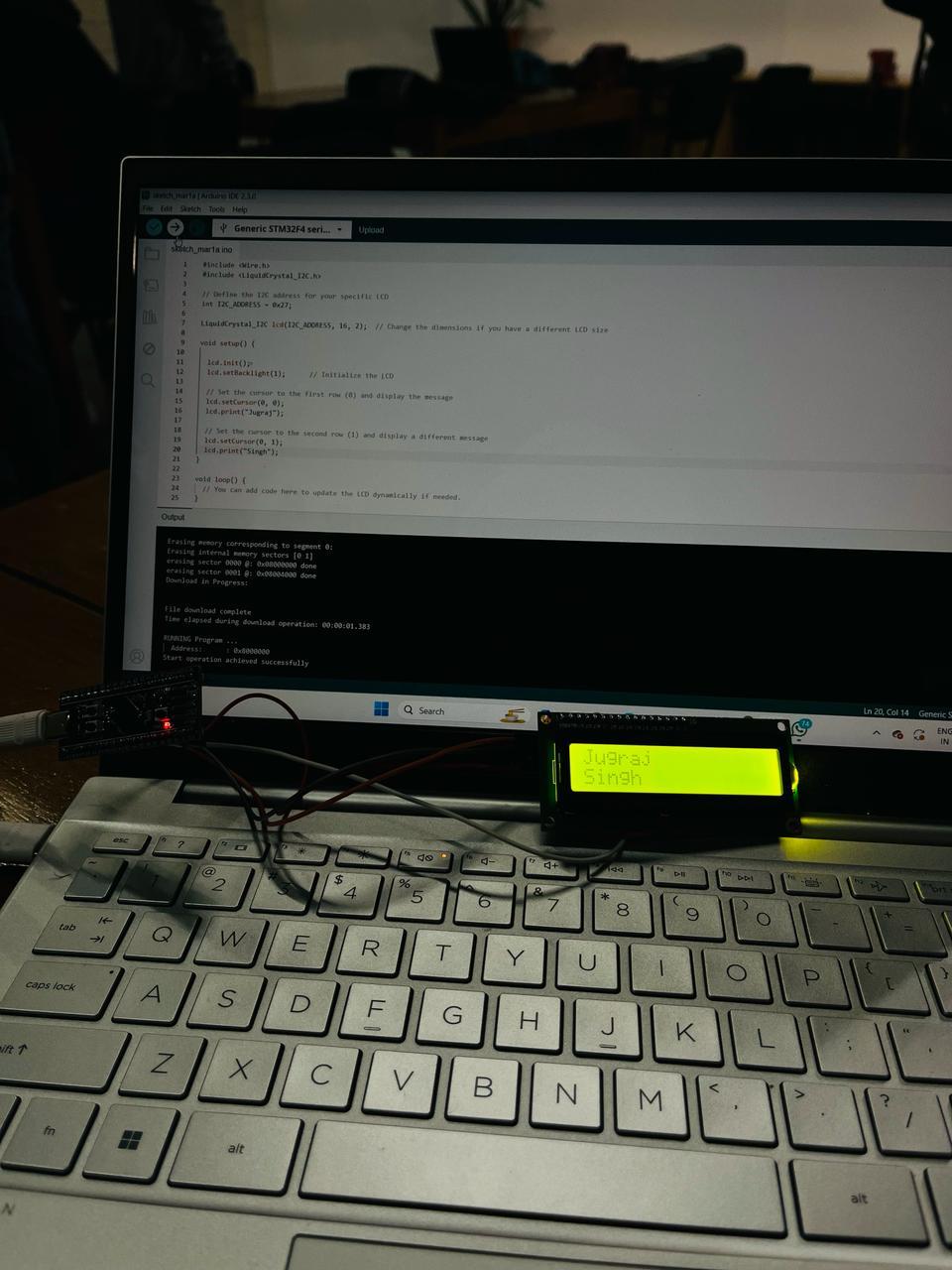
Our name is printed on the LCD as it was required!!!