Using Your Raspberry Pi's GPIO Pins to Control an LED
by ComponentsPlus in Circuits > Raspberry Pi
8524 Views, 4 Favorites, 0 Comments
Using Your Raspberry Pi's GPIO Pins to Control an LED

Your Raspberry Pi is not only an all in one computer, it is also an excellent device for controlling your electronic projects! This is because it has GPIO pins (also known as General Purpose Input/Output) which can send small electrical signals on demand.
This simple, back-to-basics tutorial shows you how to control these GPIO pins by powering a small LED and introduces you to one of the leading programming languages available for the Raspberry Pi; Python.
What You Will Need


- A RaspberryPi with Raspbian already installed. You will also need to be able to access the Pi using a Monitor, Mouse and Keyboard or via Remote Desktop. You can use any model of Raspberry Pi. If you have one of the Pi Zero models, you may want to solder some header pins to the GPIO port.
- An LED (Available here)
- A Solderless Prototyping Breadboard (Available here)
- A 330 ohm Resistor (Available here)
- Some Male to Female jumper wires (Available here)
Build Your Circuit


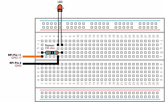
Build the above circuit on your breadboard making sure that none of the components leads are touching and that the LED is connected the correct way round.
How do you identify the positive and negative leads (the polarity) on your LED?
If you look at your LED closely, you will see that it has two small pieces of metal inside the coloured casing. These are called the Anode and Cathode. The Cathode is the largest of the two and is also connected to the LEDs negative lead.
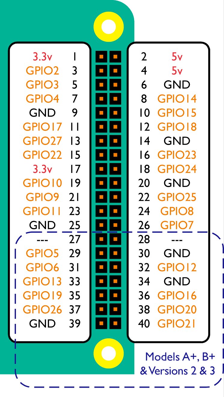
Once you have checked your circuit, connect the two jumper cables to pins 6 and 11 of the Raspberry Pi by following the above diagram.
Control the LED by Running Commands

On your Raspberry Pi, open IDLE (Menu > Programming > Python 2 (IDLE)).
First, load the drivers for the GPIO pins by typing the following:
import RPi.GPIO as GPIO
GPIO.setmode(GPIO.BCM)
We now need to tell the Raspberry Pi that we are using GPIO pin number 17 as an Output control by typing the following:
GPIO.setup(17, GPIO.OUT)
To send the electrical signal through the GPIO pin, we need to tell the Raspberry Pi to set GPIO pin 17 to True (or high) by typing the following:
GPIO.output(17, True)
The LED should light up!
To switch the LED back of, tell the Raspberry Pi to set GPIO pin 17 to False (or low) by typing the follow:
GPIO.output(17, False)
Controlling the LED With a Python Script
The above lines of code have tested your circuit, and hopefully everything is working 100%. However, it would be less than ideal to type the above lines of code every time you wanted to switch your LED on!
To get around this, we can combine all of these lines of code into a single document known as a Script. The script can then be called using a single line of code.
To create your script, open IDLE on your Raspberry Pi and open a new project (File > New File). Then type (or copy and paste) the following code:
import RPi.GPIO as  GPIO
GPIO.setmode(GPIO.BCM)
GPIO.setup(17, GPIO.OUT)
GPIO.output(17, True)
Save your project as lightswitch.py (File > Save As) in your Raspberry Pi's Documents folder.
On your Raspberry Pi open Terminal (Menu > Accessories > Terminal) and navigate to your Documents folder by typing the following:
cd /home/pi/Documents
You can now run your new script by typing the following:
python lightswitch.py
The LED should light up!
Now go back to IDLE and change the last line of the script to the following and save your script (File > Save):
GPIO.output(17, False)
Now type the following command again in Terminal:
python lightswitch.py
The LED will switch back off.
Experiment!
Now that you know the basic python code required to control your GPIO pins why not learn a bit more Python code using one of the many great tutorials on the internet.