Using TMSTM 32 for LED Blinking
by pranjal4570_be23 in Circuits > Arduino
136 Views, 1 Favorites, 0 Comments
Using TMSTM 32 for LED Blinking
Hey there, embedded aficionados! Ready to infuse some life into your STM32 Black Pill? This tutorial is your roadmap to illuminating the onboard LED. Whether you're a seasoned STM32 guru or just dipping your toes into the hardware pool, this guide provides a smooth entry point to mastering GPIO pin configuration and hardware manipulation on the Black Pill. Let's roll up our sleeves and get that LED pulsing!
Downloads
Supplies
Before delving into embedded programming, let's prepare your arsenal. Let's ensure you have the necessary tools and software:
Development Environment:
- A laptop or desktop computer
- STM32CubeIDE
- STM32CubeProgrammer
Hardware:
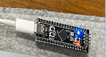
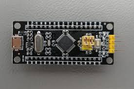
- STM32 Black Pill development board
- USB cable that's compatible with the board
Making a New Project in STM32 CUBE IDE
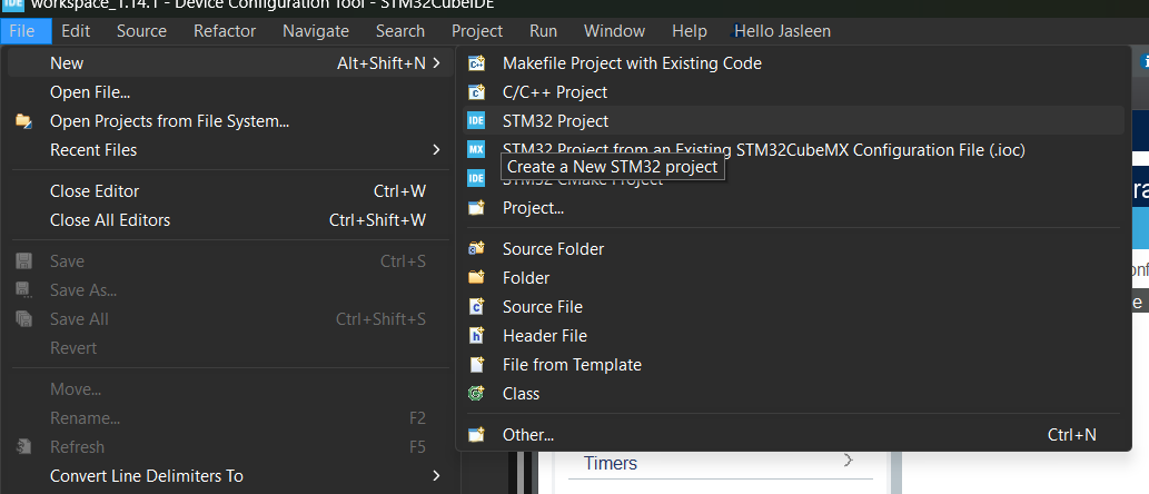
Navigate to the "Files" tab, then select "New" followed by "STM32 Project". Assign a unique name to your project to continue.
Adding Configuration to STM Board
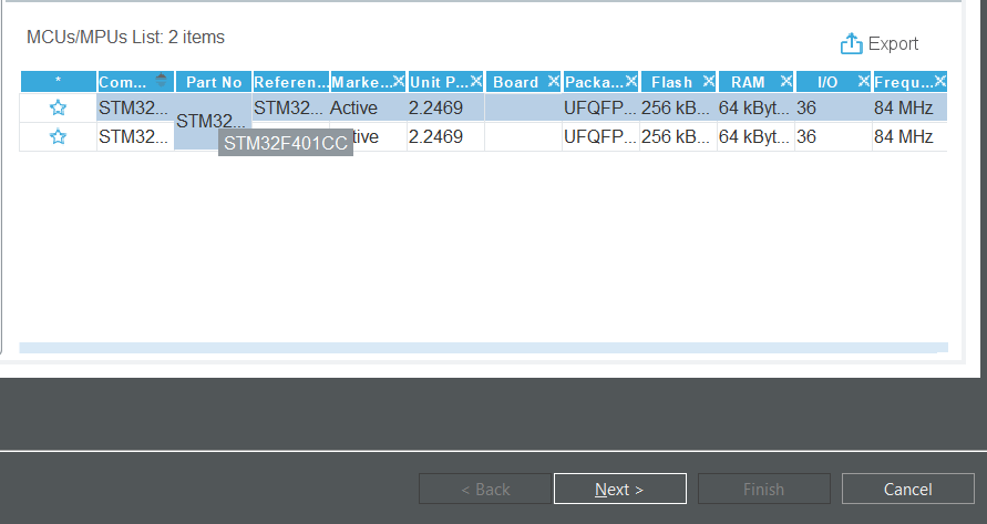
Locate the component "STM32F401CCU6" in the search bar. Once found, select the necessary component and proceed by clicking "Next".
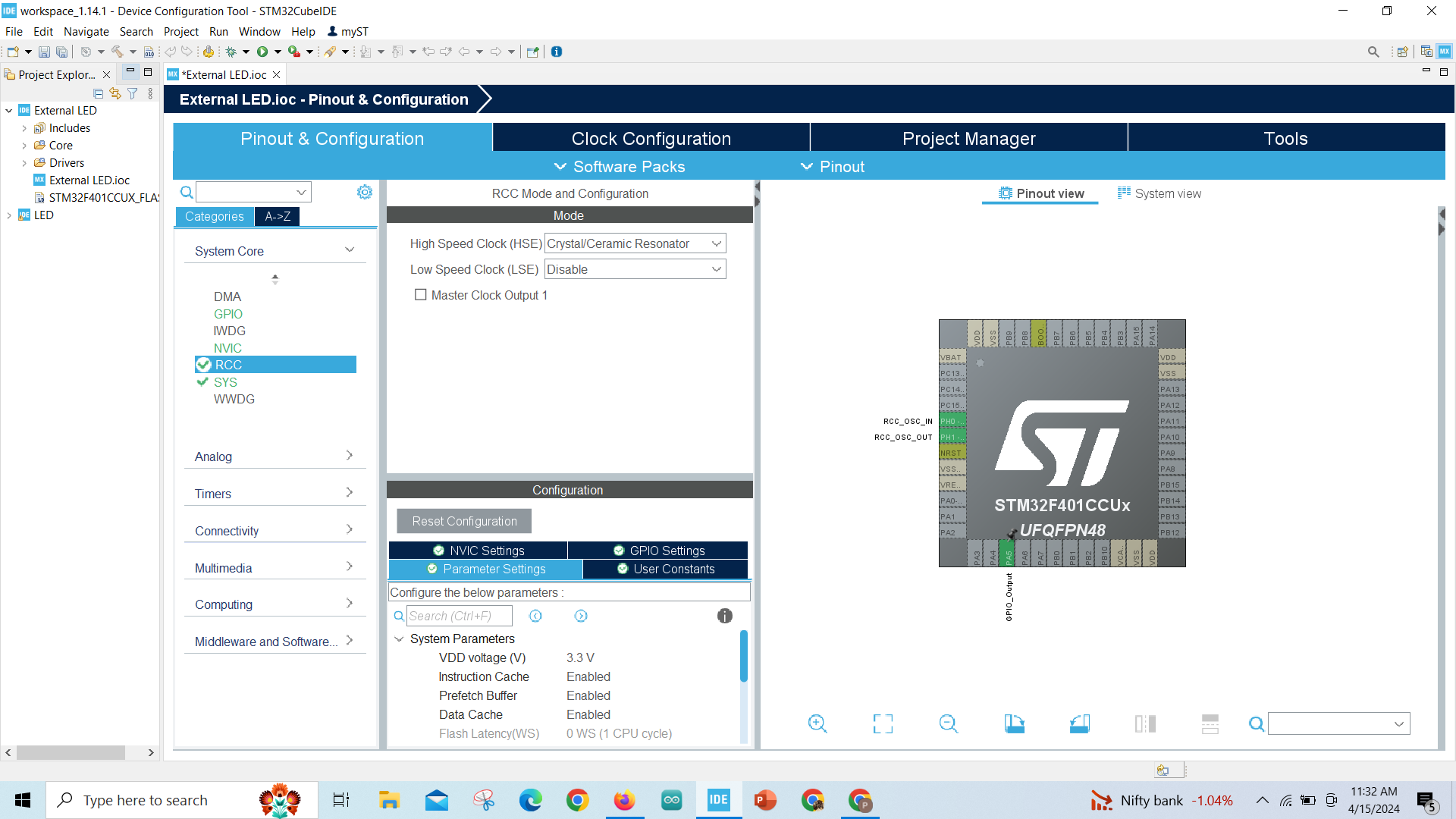
Let's Configure the Board Settings:
.png)
- In the STM32 slide, choose "STM32".
- Select pin 13 as GPIO output.
- Proceed to configure the other settings.
- Set the RCC Mode configuration.
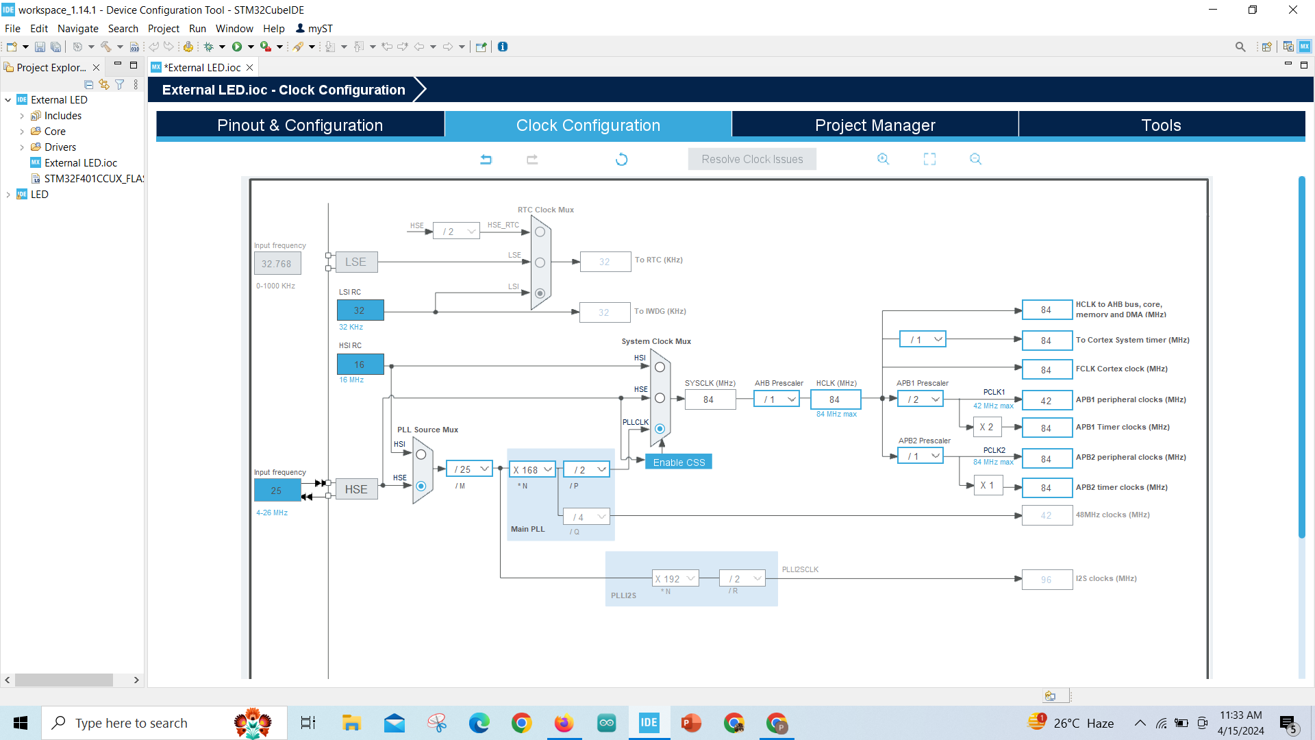
The Next Step Is to Configure the Clock Settings:
.png)
Choose the high-speed clock and set it to ceramic/crystal response.
Configuring MCU Post-Build Outputs:
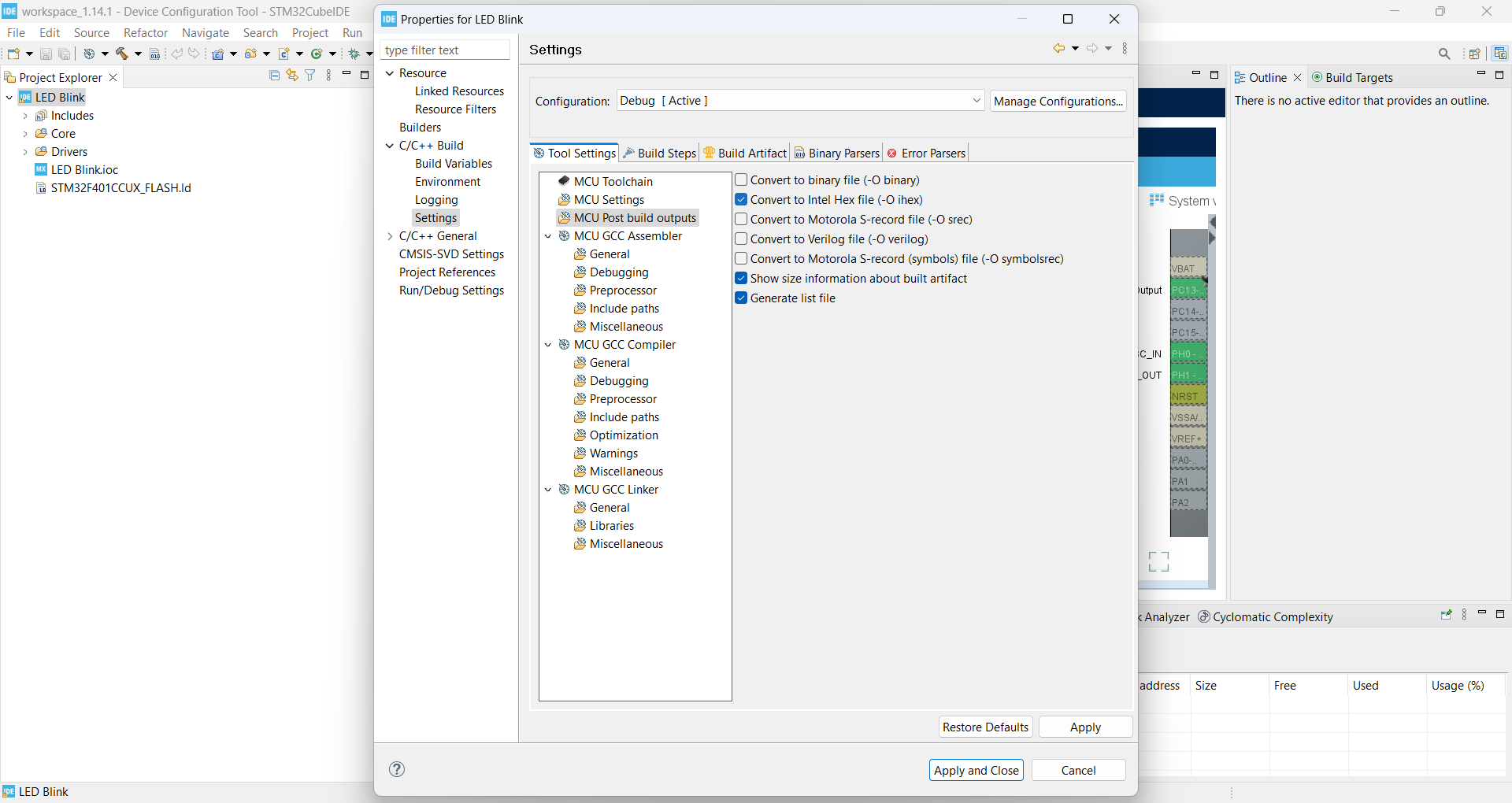
Here's how to configure MCU Post-Build Outputs:
- Access Project Properties: Right-click on your project name in the Project Explorer and choose "Properties."
- Navigate to C/C++ Build Settings: In the project properties window, find the "C/C++ Build" section, expand it, and select "Settings."
- Enable MCU Post-Build Outputs: Within the "Settings" tab, locate the "MCU Post Build outputs" section. Tick the boxes next to your preferred output options, as demonstrated in the provided image if available.
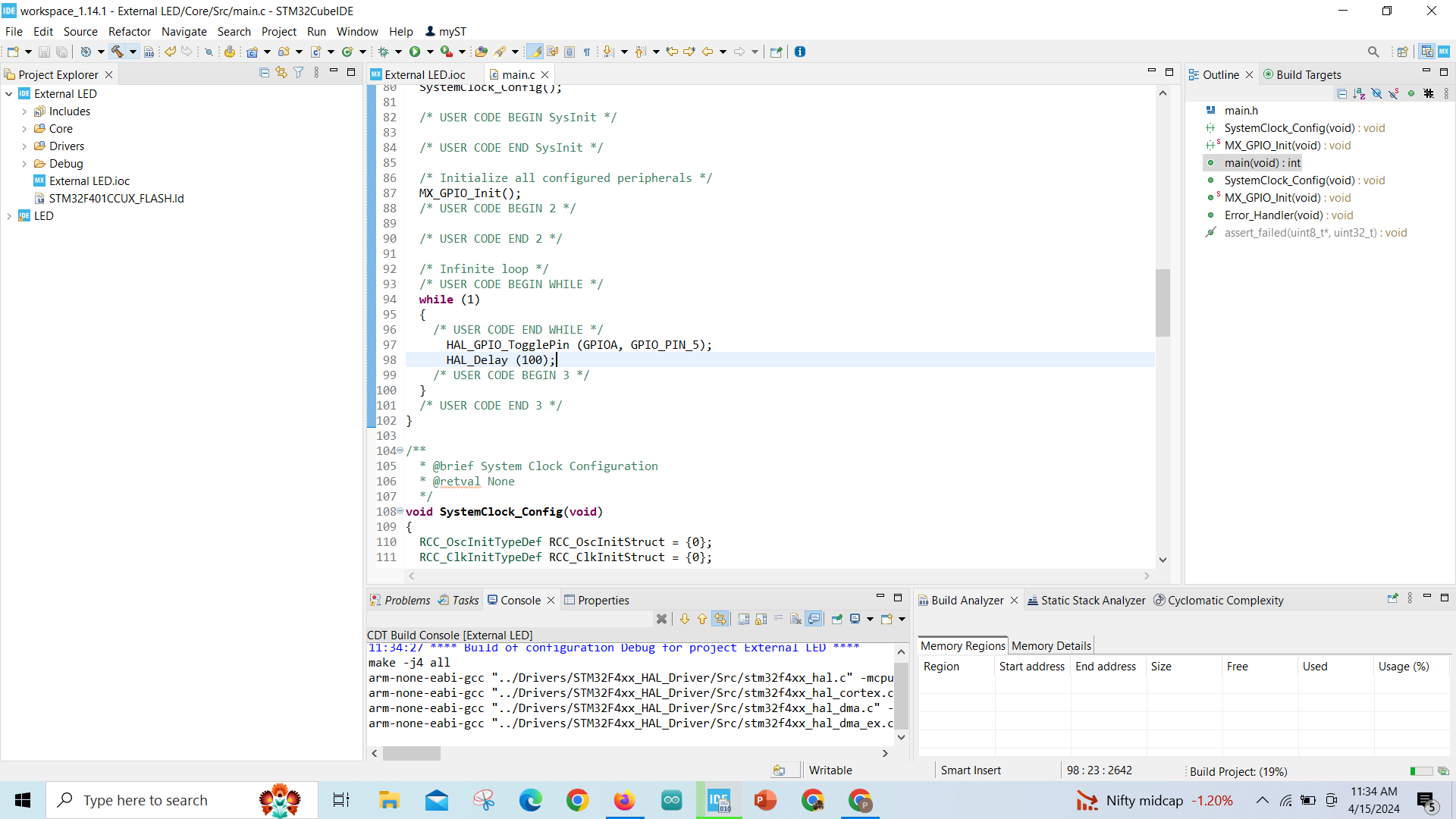
Code Configuration
.png)
- Go to the "Project" tab.
- Find and open the main.c file.
- Locate the main() function within the file.
- Inside the main() function, find the while(1) loop.
- Add your code within the while(1) loop.
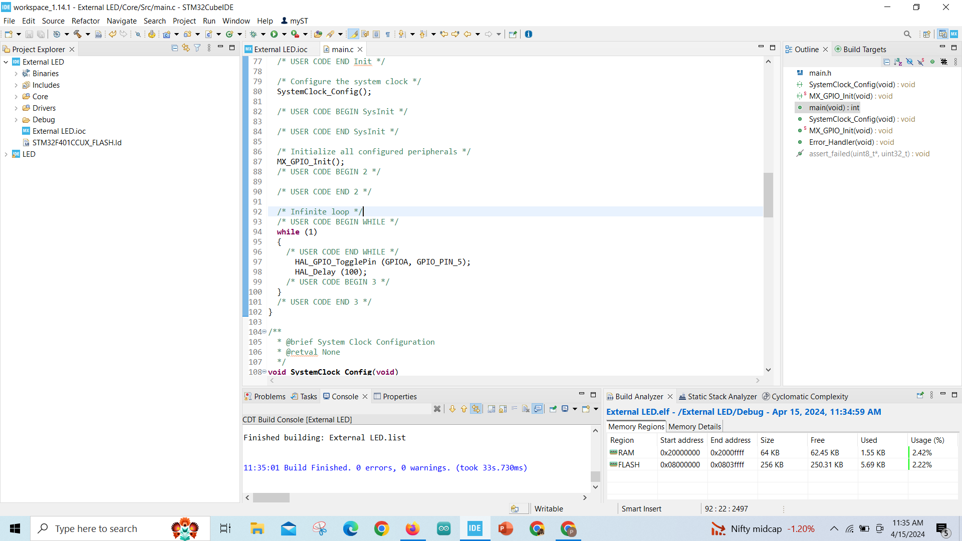
Code Building
.png)
Used GPIO Pin number 13 you can use other GPIO Pins
HAL_GPIO_WritePin(GPIOC, GPIO_PIN_13, 1);
HAL_Delay(5000);
HAL_GPIO_WritePin(GPIOC, GPIO_PIN_13, 0);
HAL_Delay(5000);
> Upload the code and wait for it to build properly and check for any error or bug!!
Debugging
.png)
Debug the code with the help of the in hammer icon in task bar.
Copying the Path of Elf File
- Locate the .ioc file:
- Search for it in the Project Explorer on the left side, listed under your project name.
- Copy the file path:
- Right-click on the .ioc file and select the option to copy its path.
- This action copies the complete file location, ready for pasting wherever needed.
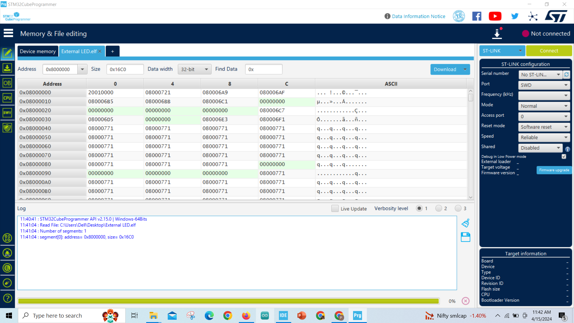
Connect Board to Programmer
.png)
- Connect your STM board to your computer via USB cable.
- In STM32CubeProgrammer, locate and select the option to connect to the board.
- Ensure that the connection is successful and the board is recognized by the software.
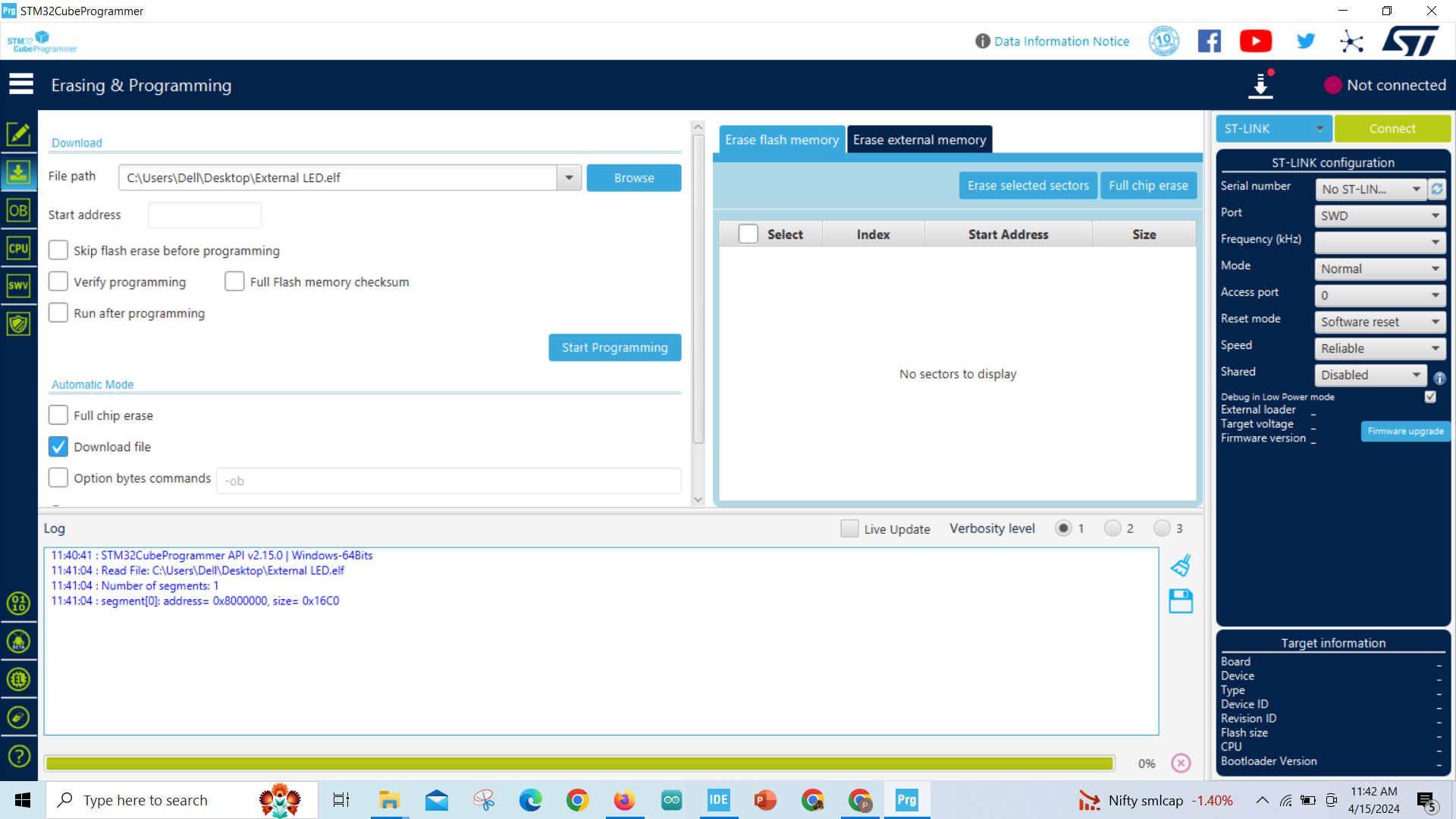
Configure Download Settings and Activate Automatic Downloads
.png)
LED Blinks