Raspberry Pi FPV on RC TerraDrone
by beaneboper in Circuits > Raspberry Pi
8880 Views, 34 Favorites, 0 Comments
Raspberry Pi FPV on RC TerraDrone
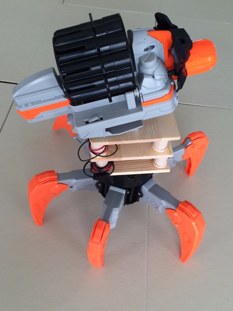
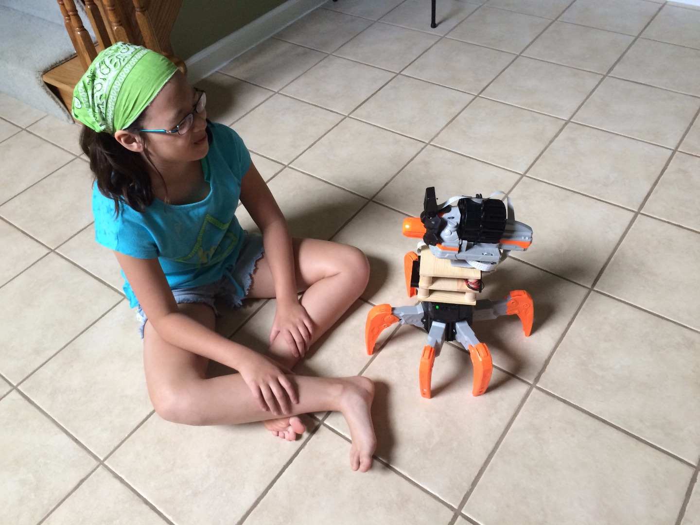

My progeny loves operating our Nerf TerraDrone named James. He is able to animate James while trying to stay out of sight so I got the idea of using the Pi Surveillance Project by Michael Castor from the April/May 2015 edition of Make Magazine to make a poor person's FPV. This build will require the usual peripherals for working with the Raspberry Pi (HDMI cable and Monitor) plus an ethernet connection.
Here are the basic electronic items you will need:
- Raspberry Pi 2 Model B
- Raspberry Pi 2 Enclosure (Tin)
- MicroUSB cable (short)
- Wireless Dongle
- Raspberry Pi Camera Module
- Raspberry Pi Camera Enclosure
- Raspberry Pi Camera Extension Cable
- 10000 mAh Power Bank
- Red and Black wires
- JST connectors
- Heat Shrink Wraps
- Nerf TerraDrone
(Note: more build items will be listed later though they are not critical)
Preparing and Installing the Raspberry Pi Camera Module
WARNING: Handle the camera module with care. Be sure to ground yourself so that you don't accident zap the camera module. It is incredibly delicate.
Items needed:
- Raspberry Pi ($35)
- Raspberry Pi Tin ($8)
- Raspberry Pi Camera Module ($25)
- Raspberry Pi Camera Module Enclosure ($9)
- 24 " Replacement Ribbon Cable ($11)
- Wireless Dongle ($9)
Switching Out Ribbon Cable
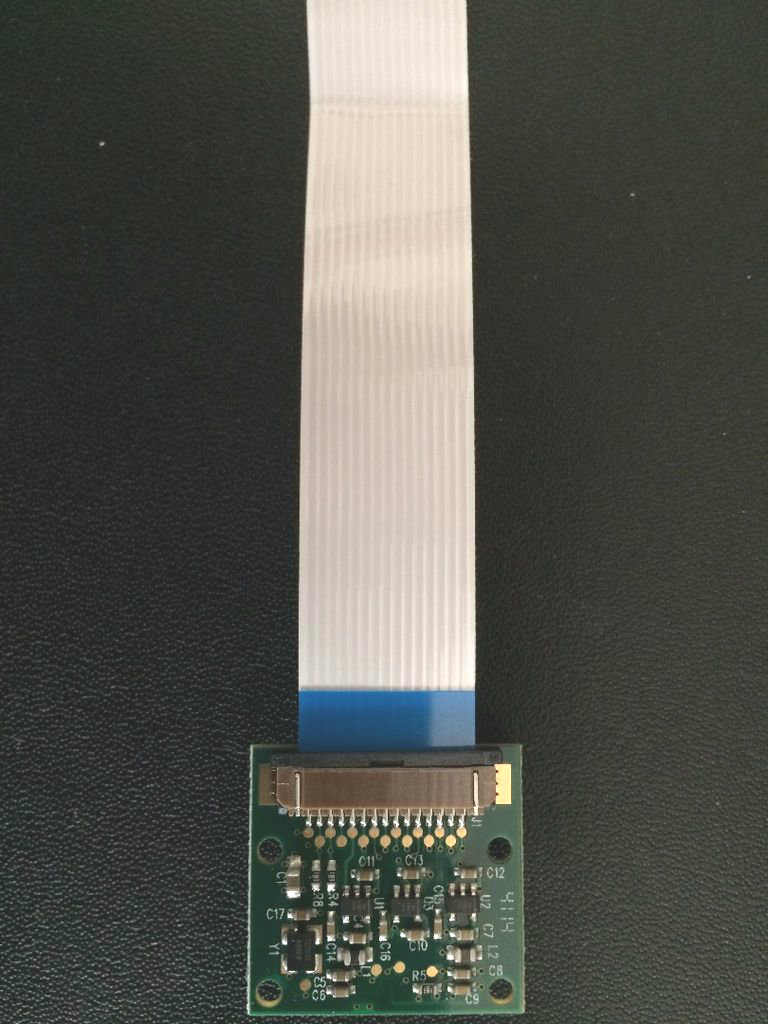
You will need to switch out the ribbon cable for a longer on. I used a 24 inch ribbon cable which might have been overkill but the standard cable was definitely too short to comfortably position the camera.
At the base where the camera and the cable are attached, pinch the black tabs on sides and pull. It should release the cable from the camera. Then install the new cable with the metal side facing the board. Slide the black tabs down to secure the cable.
Set up the Camera Module Enclosure
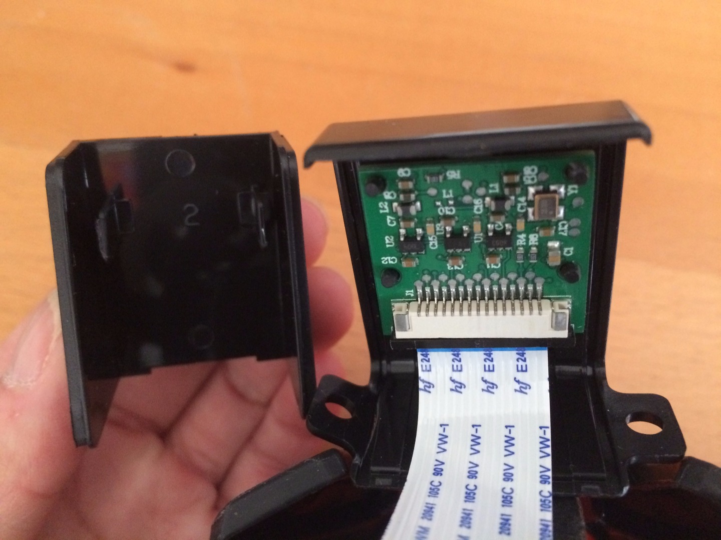
Since this is a Nerf RC Toy that shoots the sponge darts, it would be wise to protect the camera from potential abuse. This enclosure I purchased from Amazon. While it'll protect from casual contact and light impact, it will not hold up to abuse from the environment or excessive handling.
For this particular enclosure, I fitted the upper pegs through the nail holes on the board with the camera facing out. Then snapped the back piece in place. Voila. The cable will be dangling but no worries.
Set up the Raspberry Pi and Pi Tin and Installing the Camera
Again, due to the nature of the use and abuse this toy will be subjected to, I got an enclosure. It doesn't protect from impact but from casual contact and light impact. Depending on your case, you may need to half assemble it then feed the cable through the top slot. With my enclosure, I placed the Pi in the bottom part. Fed the cable through the camera cable slot and then pinched the black tabs (like before when replacing the cable) and slid the cable into the slot making sure the metal side made contact with the metal pins in the port. Slid the black tabs back down to secure the cable and snapped the top part of the enclosure with the bottom. Voila.
Configuring Your Raspberry Pi SD Card and Network

Preparing the microSD Card
Here is where I followed the Pi Surveillance article from Make step by step to download and burn Motionpie on the microSD card. Once I downloaded and unzipped Motion Pie, I used ApplePi Baker to burn the image onto the microSD card.
Configuring Your Pi and Motion Pi Network Configurations
Plug an ethernet cable for network connection, HDMI Video (to follow along with the install) into your Raspberry Pi. You don't need to connect a keyboard or mouse. It won't work so don't bother.
Then insert the microSD card you just prepared and power the Pi. Once you reach the login prompt on the Pi, find the IP address of the Pi and use your browser to reach it. Again, I used the Fing app that was recommended in the article to find the IP address assigned to the Pi and plugged in the IP address in my web browser.
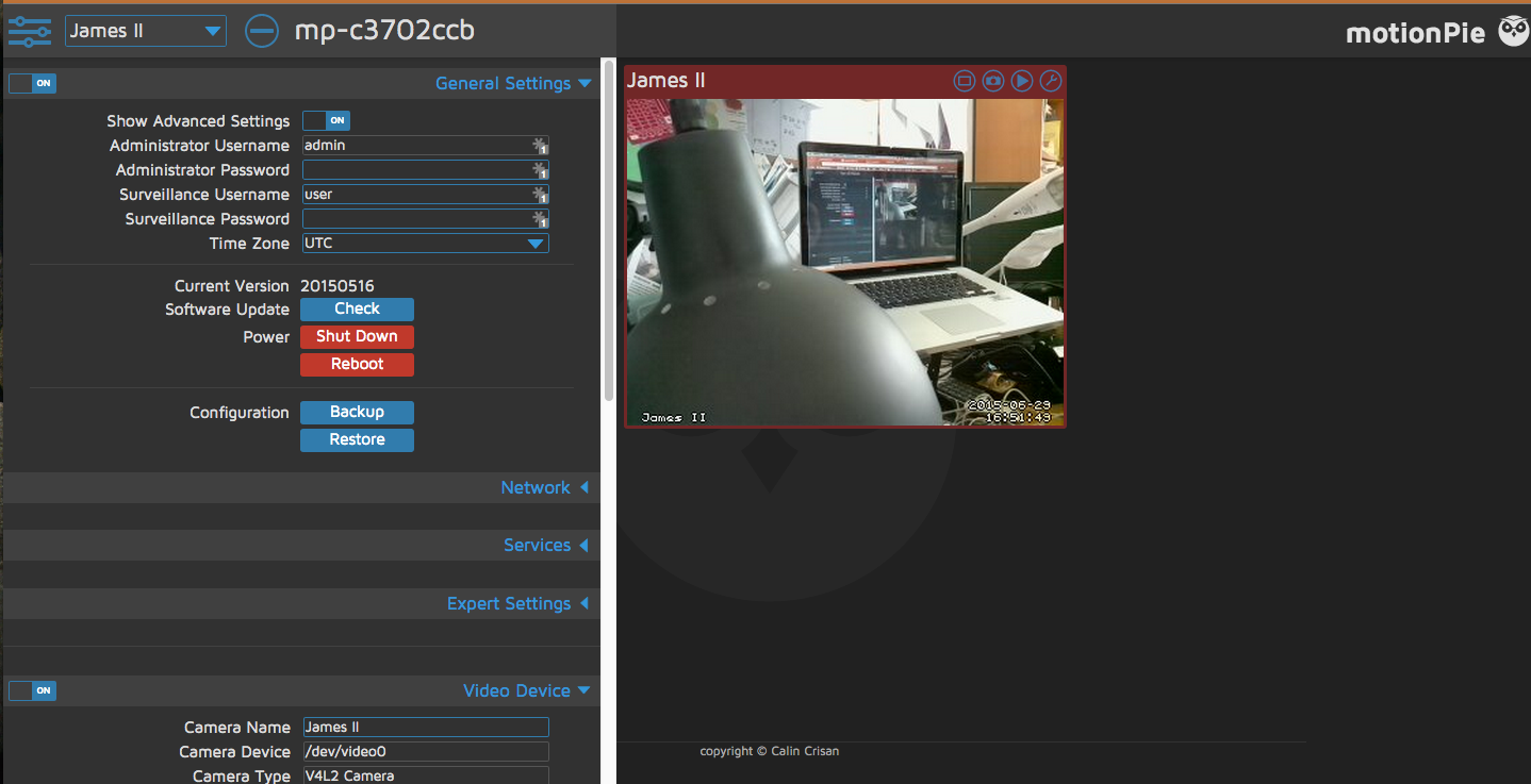
You should get your Motion Pie website and a feed from your camera. You will need to login. The default username: admin and the password is blank.
Configuring Motion Pi Settings
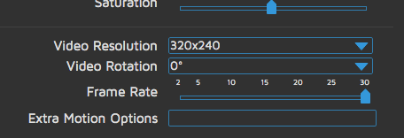
Click on the slider bar for settings. You will see the General Settings etc.. Go to the Video Settings: increase your video Frames Per Second (FPS) to the fastest it can go otherwise there will be a significant delay. I also renamed my camera to James II in this section.
Next, turn on the Advance Setting and configure the Network Settings. Enter your Wifi settings and then configure to a static IP and enter the IP address you found with Fing earlier.
Save your settings and reboot. Quickly disconnect your ethernet cable.
Now your camera is live and on your wifi.
Power it down and set aside.
Now for the challenging part: Modifying the RC TerraDrone.
Soldering Longer Wires and New JST Connectors
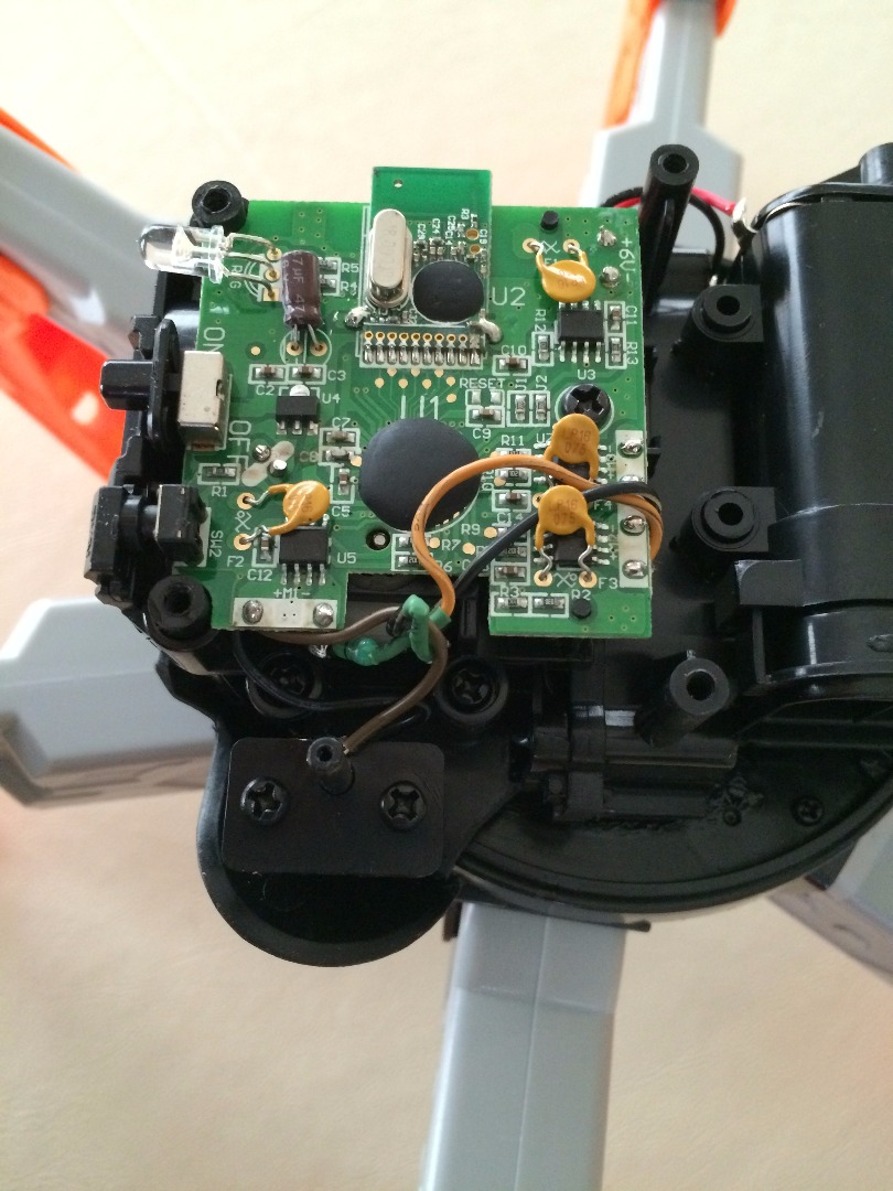
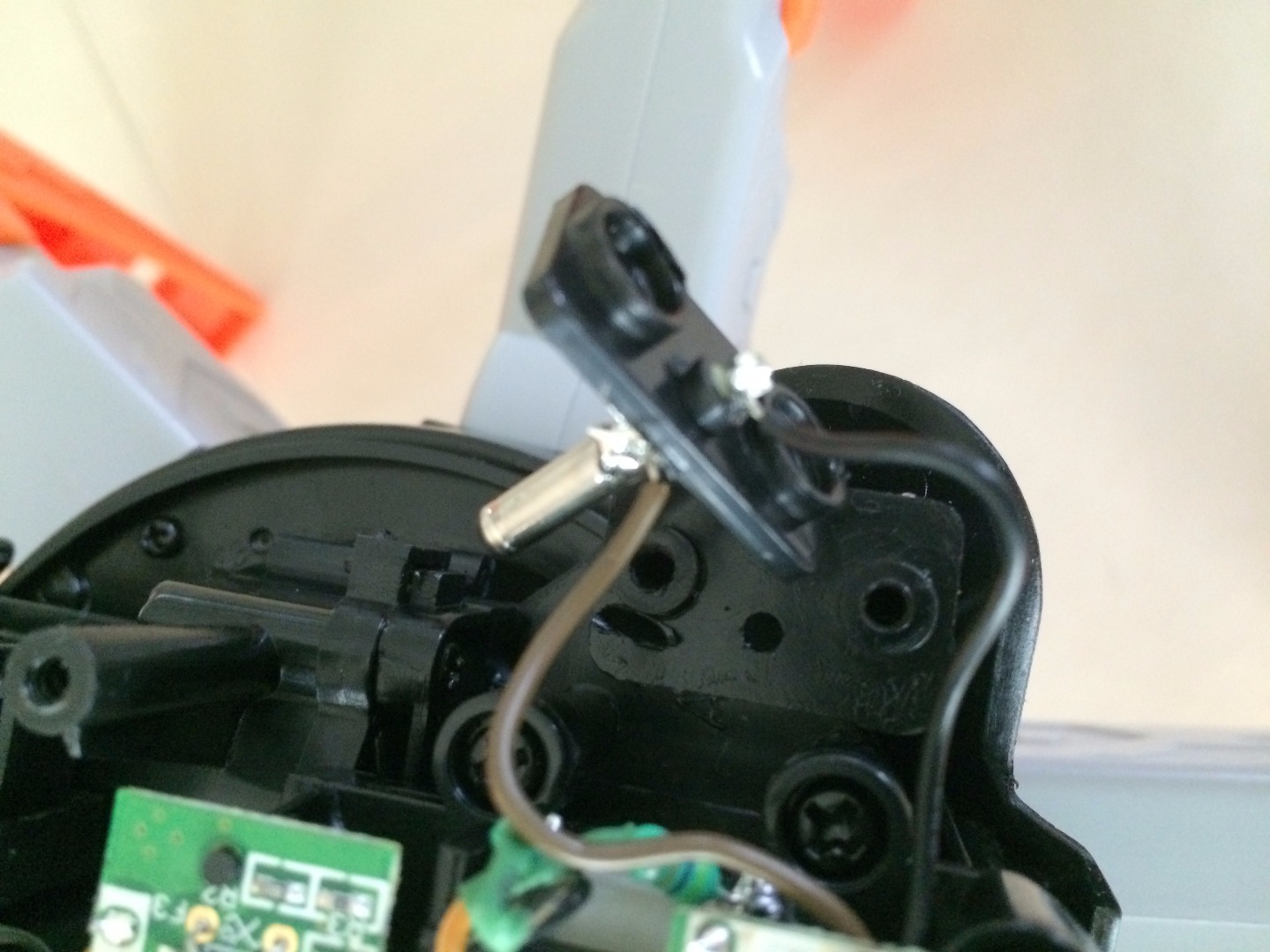
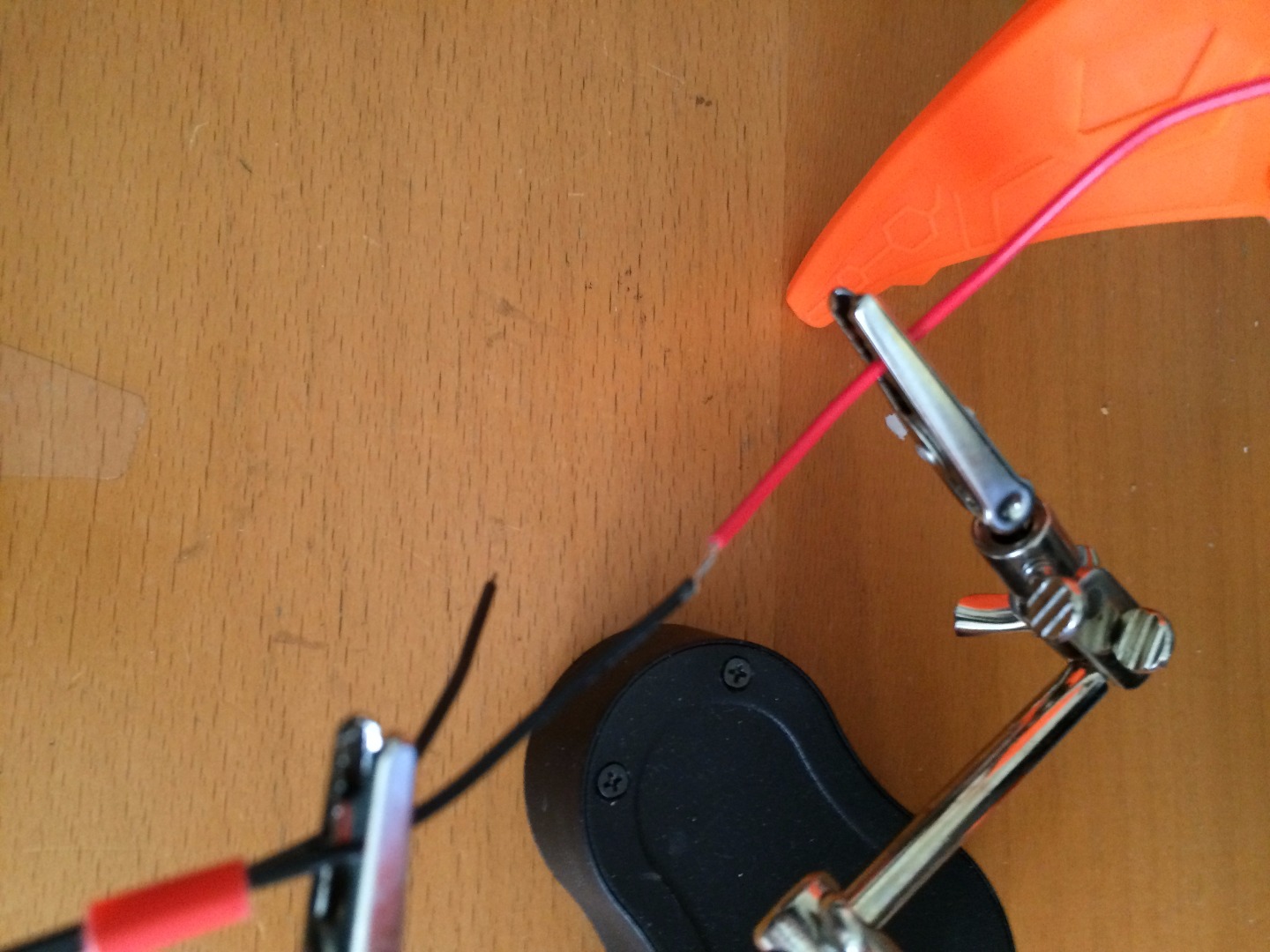
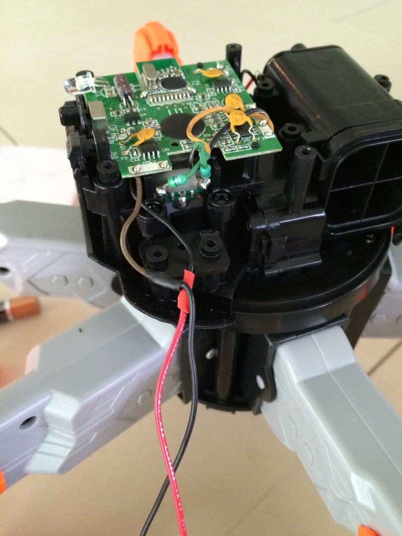
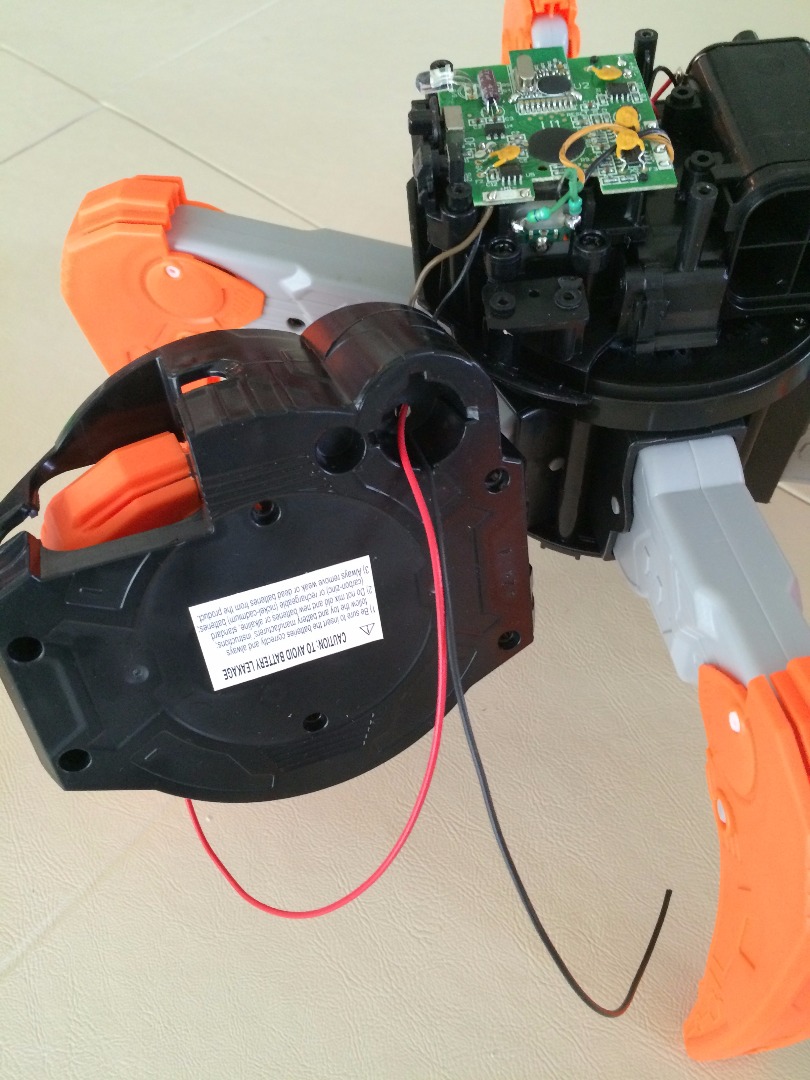
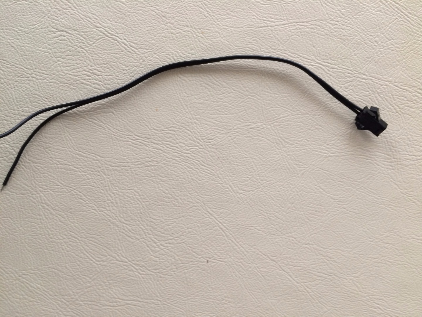
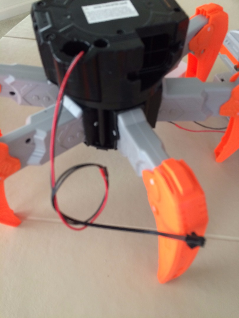
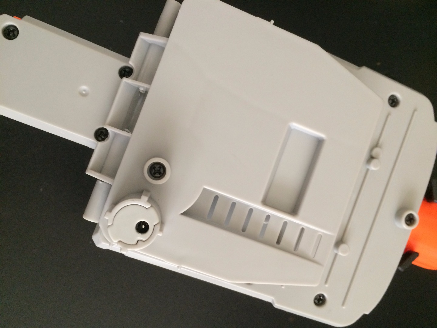
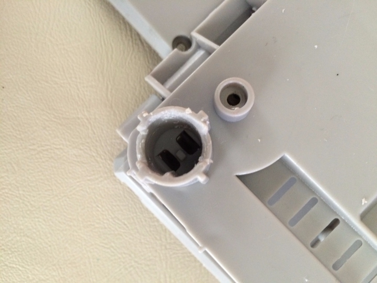
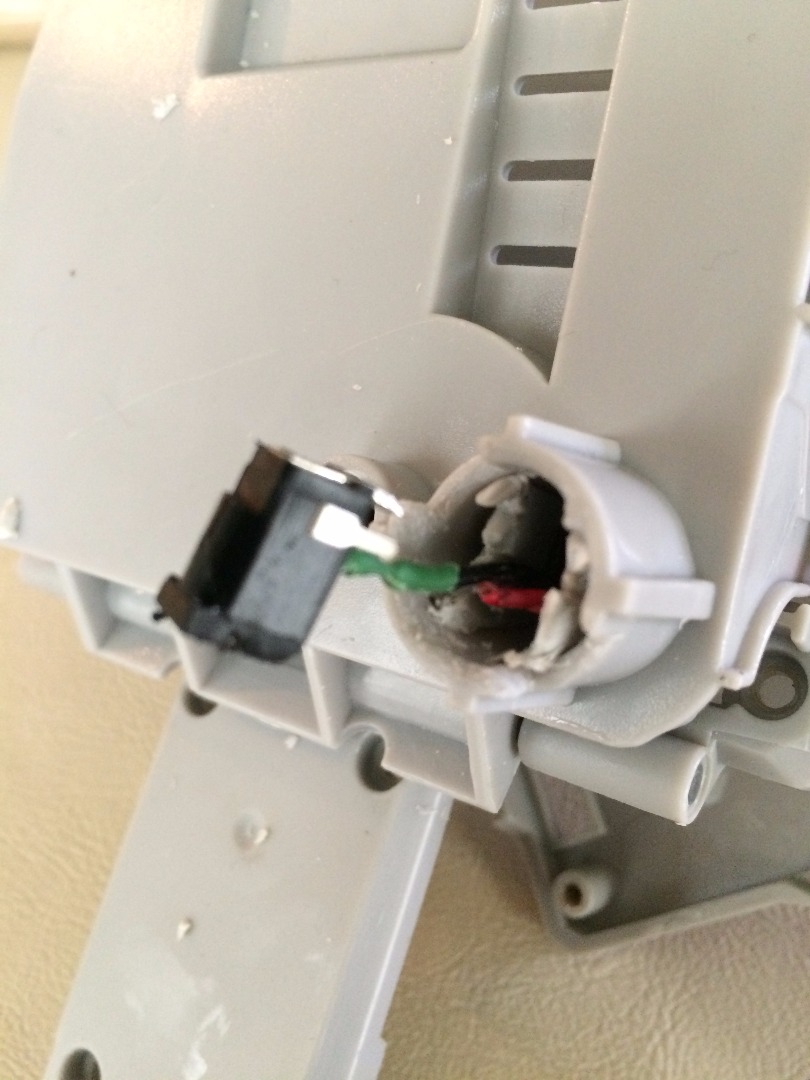
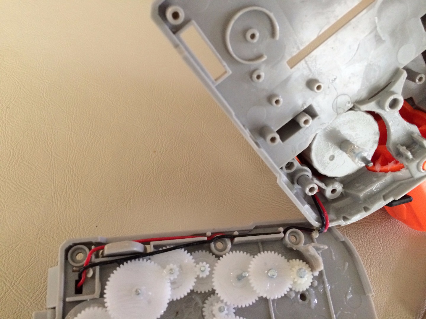
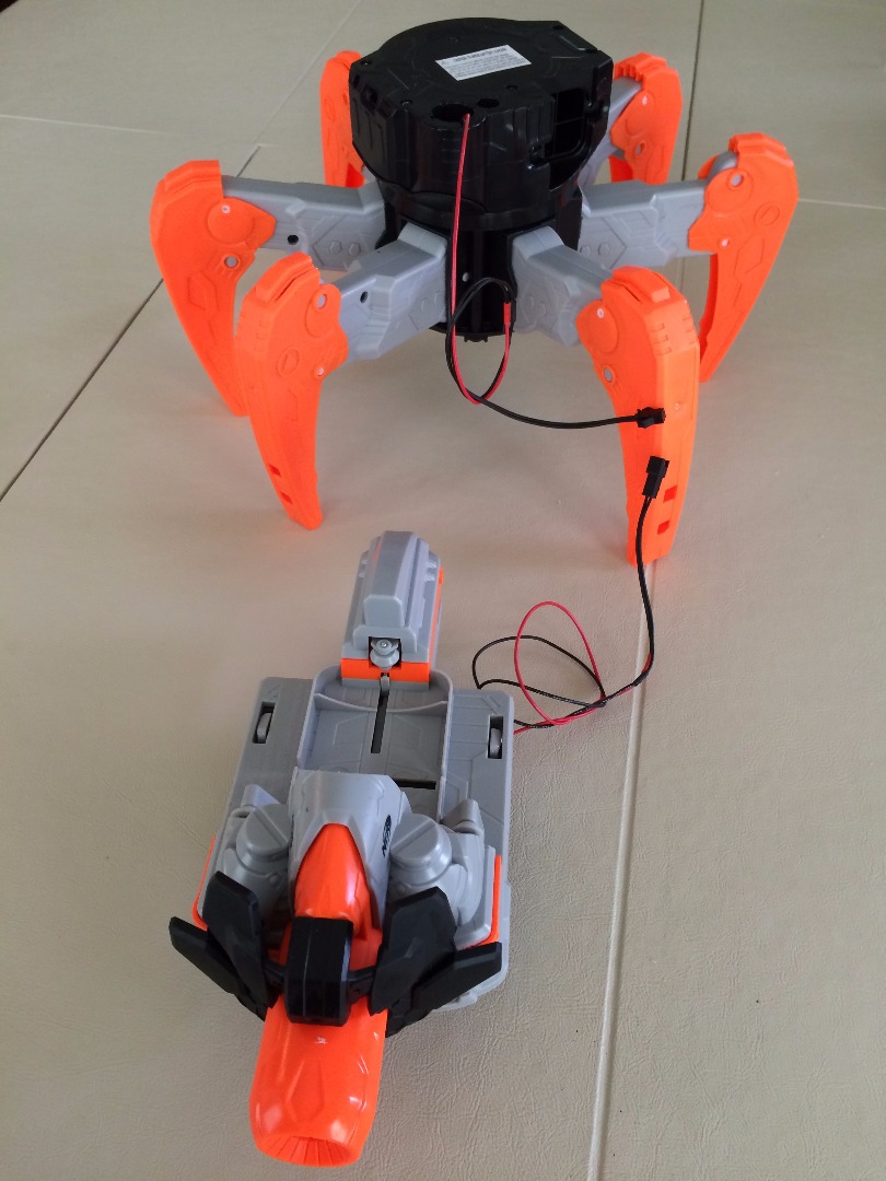
The TerraDrone is connected with a barrel connector which we will need to replace. In this case, I replaced it which JST connectors. I recommend you start with the body and then do the head. When I worked on it, it was the reverse order and there was a lot of spitting and cursing. Hopefully, you'll be able to learn from my mistakes.
Materials needed:
- Nerf TerraDrone ($85-90)
- 2 sets of red and black wires (I was overly generous but figure it's best to have more rather than less)
- JST connectors (1 male and 1 female) ($.75 each)
- heat shrink wrap (8 pieces)
- Solder
- Soldering Iron
- Screwdriver
- Heat Gun
Changing Connectors on the Body
Extending the Wires
First, separate the TerraDrone's head from it's body. We'll tackle the body first (It's easier). Be sure to remove all batteries and have the power button off.
Open up the case and unscrew the barrel connector. Note which wire is Positive and Ground. I cut and striped the wire and the extension wire and soldered them together. Protect the soldered wire join with heat shrink wrap. Do this again with the second wire. Feed the wires through the hole through top of the body and screw it back together.
Adding JST Connector to Body Wires
Next, slide the heat shrink wrap down the wires far away from where we will be soldering. Stripe the other end of the extension wire. Solder the JST connectors to both the Positive and GROUND wires. Now shimmy the heat shrink wrap up to the join between the extension wire and JST wire and shrink wrap the area.
Voila. Set aside.
You will be doing the same to the head. However, this part is a little tricky.
Extending the Wires and Changing Connectors to the Head
Extending the Wire
This you will need to first rip out the plastic piece securing the barrel connector. This took me awhile. Don't unscrew the top yet. There are a lot of cogs and pieces that will fall out. Also, do not unscrew the screw right next to the barrel connector column. Once you clear away the plastic, exposing the wires, cut the wires as close to the connector as possible. Now, carefully, unscrew the screws holding the head together (DO NOT UNSCREW THE SCREW NEXT TO THE CONNECTOR). Carefully set aside the parts and gently pull it apart. Loosen the wires and solder to the extension wires and heat shrink wrap the joins like you did before. Feed the extension wires through the barrel column. Carefully, put the head back together.
Adding JST Connector to Head Wires
Next, slide the heat shrink wrap down the wires far away from where we will be soldering. Stripe the other end of the extension wire. Solder the JST connectors to both the Positive and GROUND wires. Now shimmy the heat shrink wrap up to the join between the extension wire and JST wire and shrink wrap the area.
Building the Housing for Pi and Power Bank
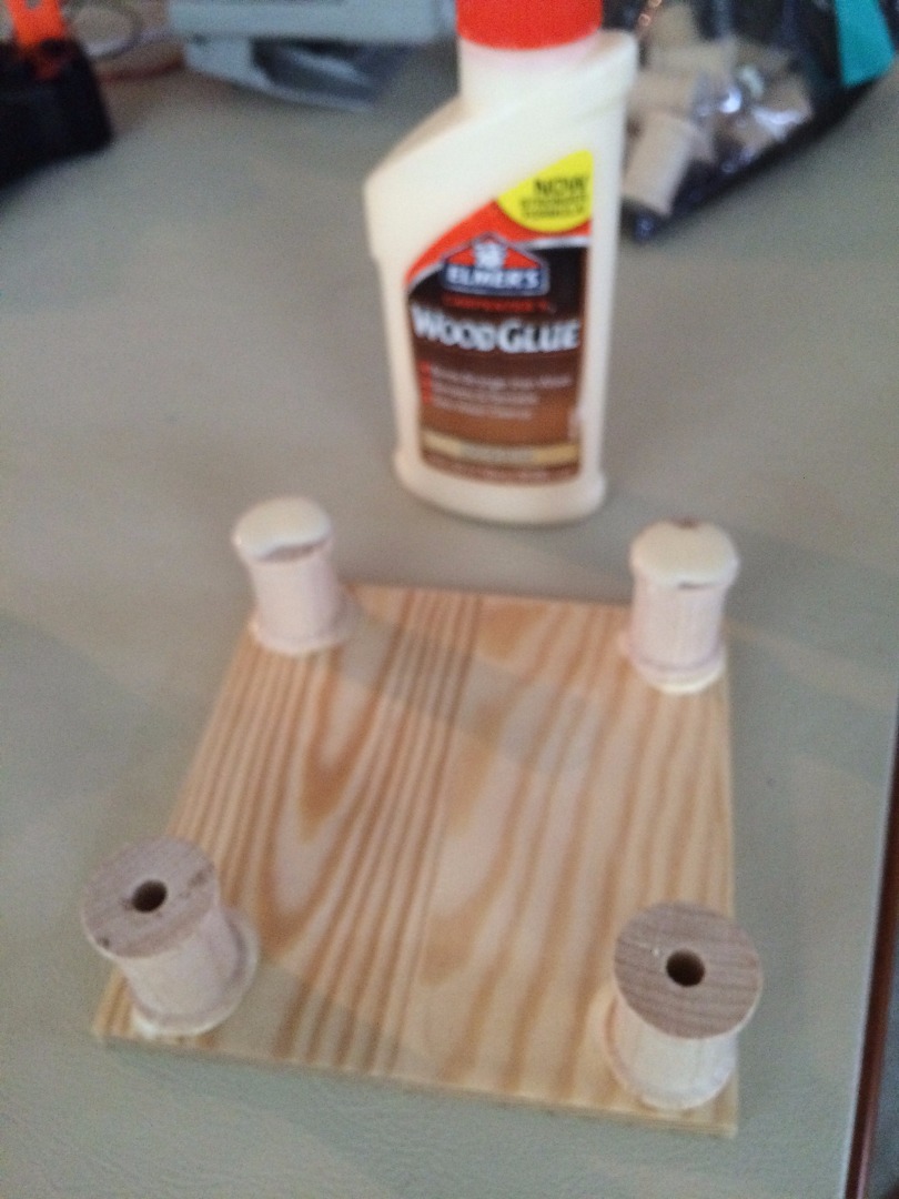
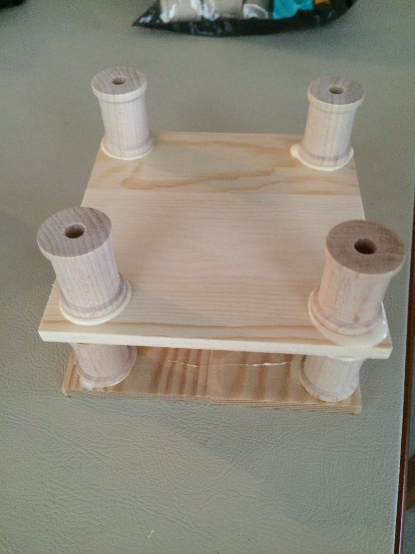
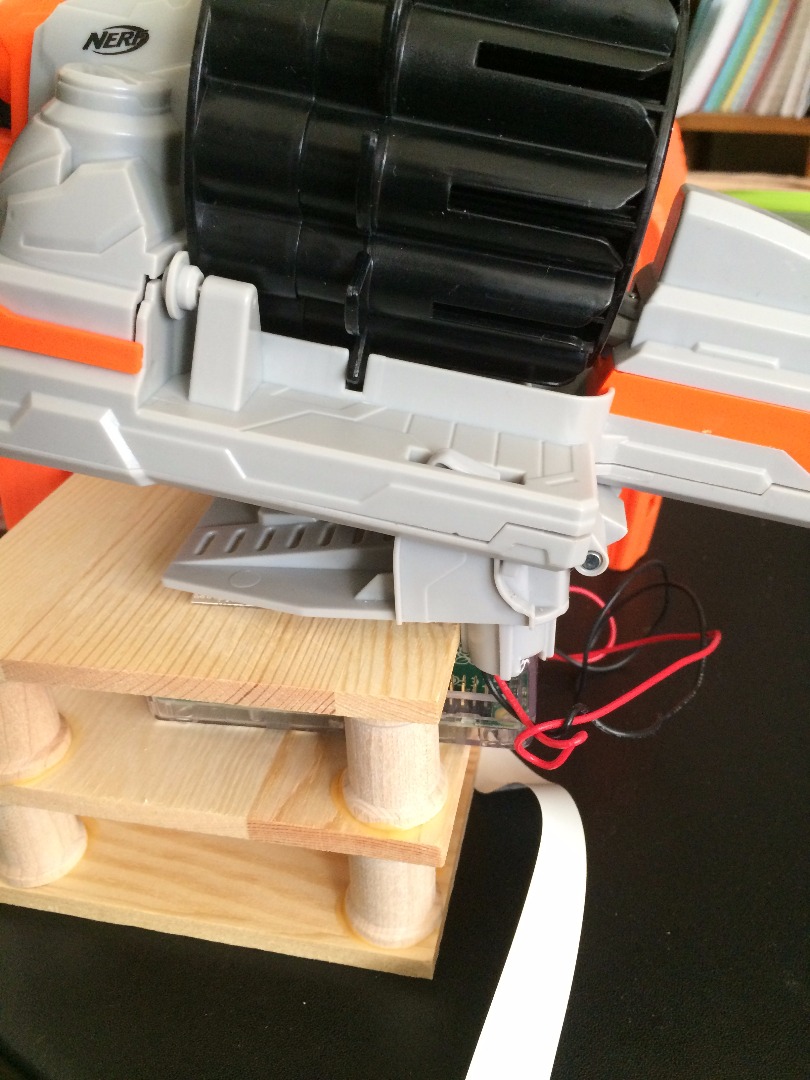
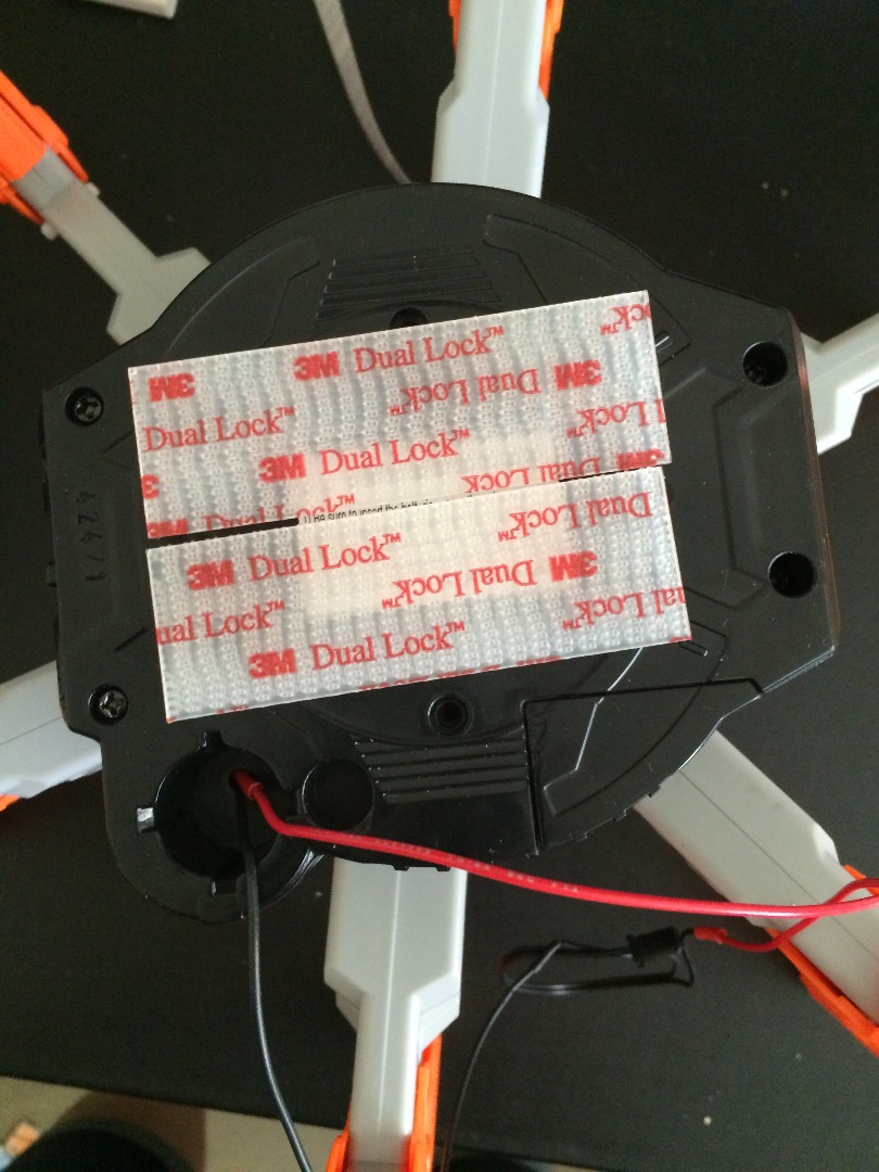
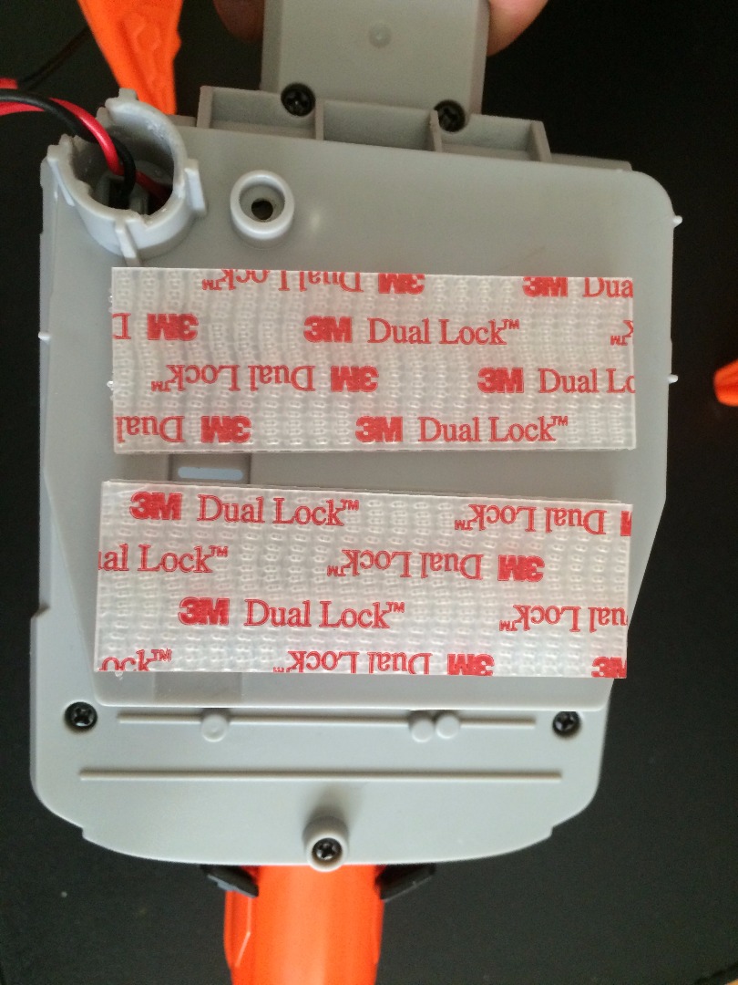
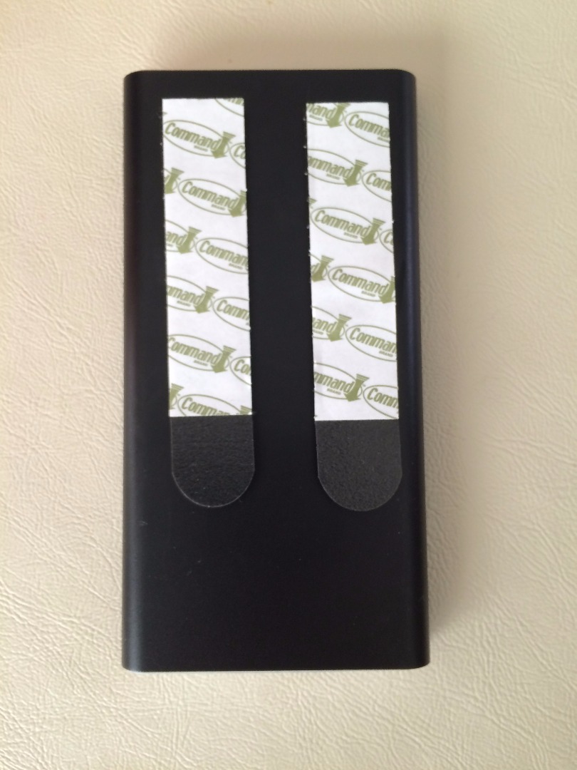
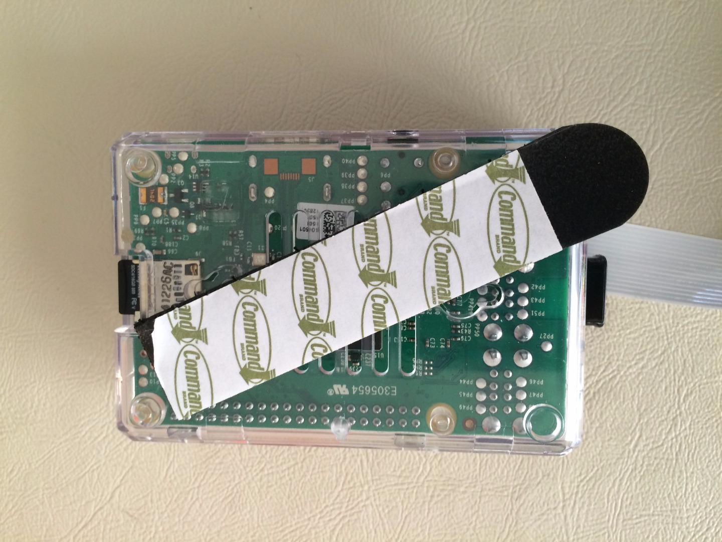
Okay, this is completely a quick and dirty prototype. In the future, I intend of designing and 3D printing a better casing (and will put it up on Instructables when I do) but for the sake of time and the Raspberry Pi build night deadline, this was my workaround. I also learned the hard way that there is right way and wrong way to put the head on. Luckily, the velcro was very forgiving and I could turn and push to attach the head.
Materials:
- 3 4.5in squares of wood (purchased at craft store 2 pack for $1.99)
- 8 Large Barrel Spools 3/16" x 7/8" (purchased at craft store: bag of 20 $3.99)
- Wood Glue
- 4 Sets Outdoor Velcro (2 sets for $6.00)
- 3 Pairs Command Picture Hanging Strips (6 sets Medium Strips for $6.00)
I glued the spools at the four corners of the boards and set it aside to dry overnight. I tested to see if the Pi and Power Bank fit. Unfortunately, the Power Bank was a little too wide so I had to saw off part of the spool to make room.
Next, I applied the outdoor velcro to the bottom side of the wood sandwich and to the body of the TerraDrone. I did the same for the head though the little piece of the head had to hang off the side.
Then, I put the Command Strips on the Pi Enclosure to secure it in place. The Power Bank is wedged in pretty good but I put a set on it for good measure.
Set everything aside and allow the velcro and Command Strips to set according to directions.
Positioning and Securing the Camera on the Head
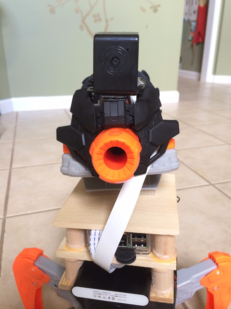
Once everything is set, carefully put it all together securing all loose wiring. The camera should be untangled and off to the side. When the body, electronics housing and head are put together, it's time to position the camera.
I placed it right above the firing barrel and secured it with a small set of Command strips which I cut to size. It holds really well. You may want use something stronger for a permanent build but the materials described are great for a prototype first run. Secure the cable for your final version as well. I haven't done so as I will play with it some more but will use more Command Strips to hold things in place.
Power Up - It's Alive
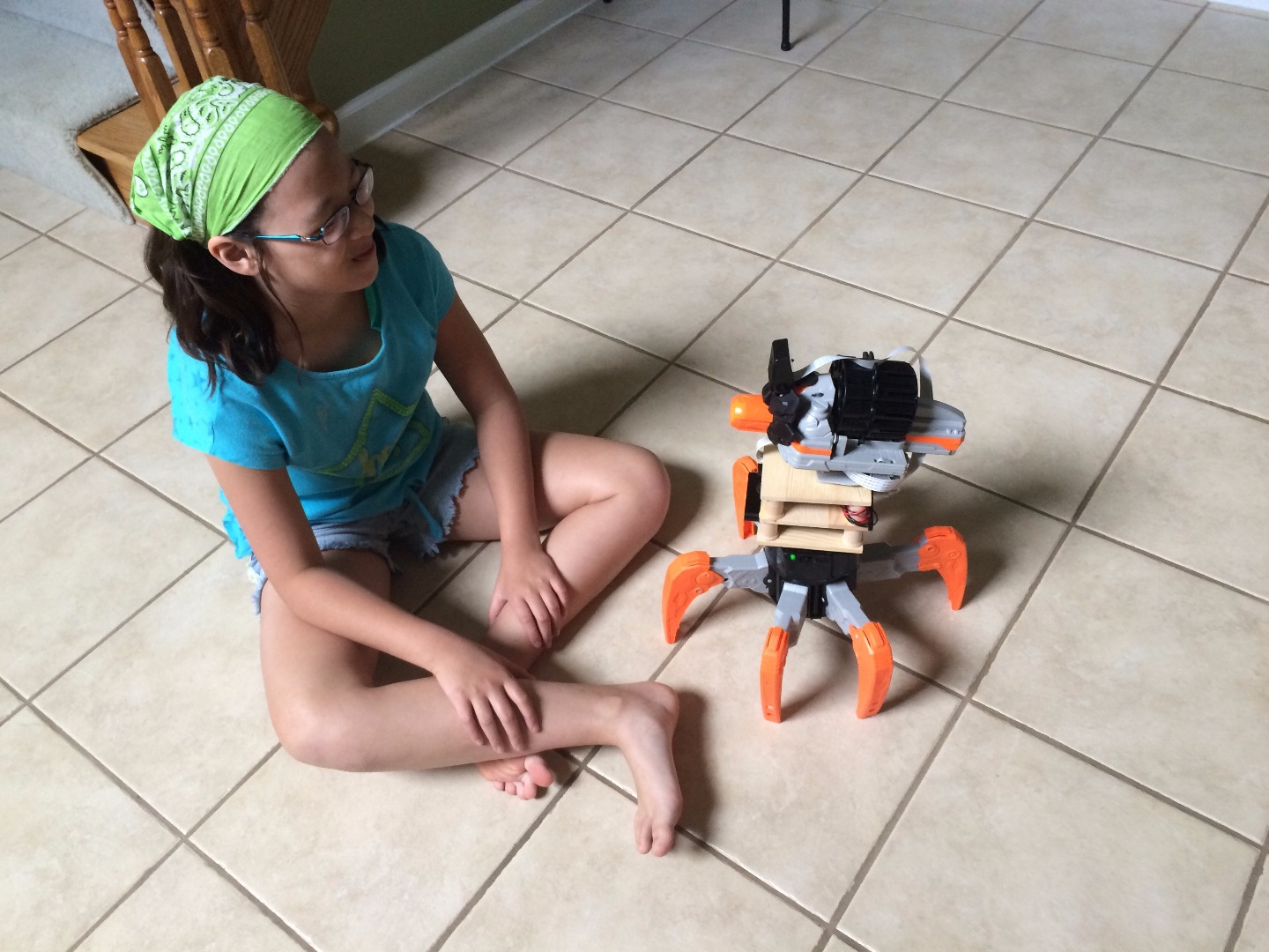

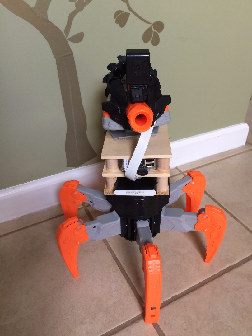
Connect Power:
Connect the power bank to the Pi and give it some time to boot up.
Then go to your browser and enter the IP address and voila!
Use your remote to control your TerraDrone. It can still fire and raise its head.
Troubleshooting:
It won't raise its head: Be sure to have the dart barrel secured in place. If it's loose, the head controls won't work.
There is a huge delay in the video: Check your Motion Pi Video settings. Make sure you have the highest frames per second possible.
My browser can't find the page: Be sure to configure the wireless setting and rebooting before disconnecting the ethernet connection. I also had to make sure I used the static IP settings and not the automatic.
Variations and Upgrades:
In the future, I intend of designing and 3D printing a better casing (and will put it up on Instructables when I do). I'll also need to add a heat sink to the Pi as it'll mostly be entirely enclosed. Not sure if I'll try to make it more water resistant, we'll see how that goes.
I'll also swap out the Pi 2 with an A+ once it's all configured see if that works as it doesn't need a keyboard input. All modifications are done remotely.
If you want to get really fancy, get a cheap tablet with wifi capability and a bracket to attach to the remote. Now you can sneak around as far as your wifi can reach both your tablet and Raspberry Pi.
Thank you for checking out my Instructable and hope it inspires you.